First Production Batch Approval Checklist for Custom Automotive Parts
By LK MFG · November 12, 2026
A sample can fit and look right while the first production lot uses a different fixture, material batch or finish route. Before releasing that lot, agree on the checks that protect fit, appearance and repeatability.
What to confirm before release
Match the lot to the approved drawing and sample. Review the agreed inspection results and any open deviations. Record who can release the batch.
▤Confirm the baselineDrawing revision and approved sample
⌕Check the evidenceFit, finish and inspection results
✓Record the decisionRelease the lot or document the hold
In custom aftermarket auto parts manufacturing, an early sample may be made with different tooling, a different fixture or a smaller batch of material. Ask your supplier to identify planned changes before the pilot run. Then decide which changes need another fit, finish or dimensional check.
What to verify before releasing the first batch
First production batch approval checklist
Review item
Evidence to request
When to hold release
Drawing and configuration
Part number, drawing revision and approved deviations
The revision differs or an exception remains open.
Material and finish
Agreed grade and finish, plus lot-linked records where required
A substitution lacks approval or a required record cannot be linked to the lot.
Critical features
Measured results, inspection method and sampling scope
A critical feature is out of tolerance or the agreed check is missing.
Fit and appearance
Check against the mating parts and approved finish sample
The part fails installation, tool access or appearance requirements.
Release responsibility
Batch ID, disposition of open issues and authorized reviewer
An unresolved issue has no approved disposition or owner.
Agree on inspection evidence during the RFQ
If you need first article inspection documentation, list the required characteristics, report format and any certificates in the RFQ. Ask the supplier to confirm cost and timing for that scope. For repeat orders, agree on the checks and records required for each lot.
When evaluating an aftermarket CNC parts supplier, use the same revision and acceptance criteria across quotes. Review the proposed CNC machining process with the supplier, then use DFM analysis to flag features that may need a different setup or inspection method before the pilot run. If a bracket’s mounting holes control assembly fit, ask how those holes will be measured. If the installer also needs room for a socket, include an assembly check with the intended hardware.
Worked example: releasing a CNC mounting bracket
A bracket bolts to a formed panel. The mounting face seats against the panel, two holes locate the bracket, and an installer needs room for a socket. The approved drawing defines the hole requirements and any datum references. The assembly check verifies that the bracket seats and the socket can reach both fasteners.
Release decision. If the inspection report confirms the hole locations but the socket cannot reach one fastener, hold the batch and record the installation issue. Agree on the corrective action and repeat the affected checks before release.
Put the release decision in writing
Identify the drawing revision and sample that define acceptance.
List the results required before the batch can ship.
Agree who can approve deviations and who can release the lot.
SEMA Show 2026 Recap: From Show Builds to Production-Ready Parts
By LK MFG · November 9, 2026 · Las Vegas
A display car makes the shape easy to see. A UTV makes the packaging constraints easier to spot. Walk the SEMA floor with those two ideas in mind and you have a useful starting point for an automotive aftermarket RFQ.
SEMA Show 2026 took place November 3–6 at the Las Vegas Convention Center. These written show notes use four show-floor photos to explore how buyers can specify appearance parts, UTV accessories and vehicle electronics hardware for repeat production. Official show details
What buyers can take from SEMA
Use the same drawing revision and quote scope with each automotive aftermarket parts manufacturer. This gives purchasing a fair cost comparison, gives engineering a clear sample approval plan, and exposes fit or quality risks before the buyer commits to tooling.
1. From styling to fit and finish
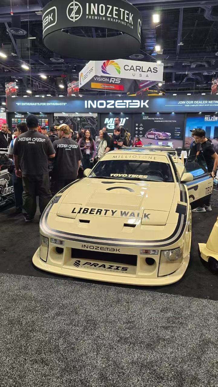
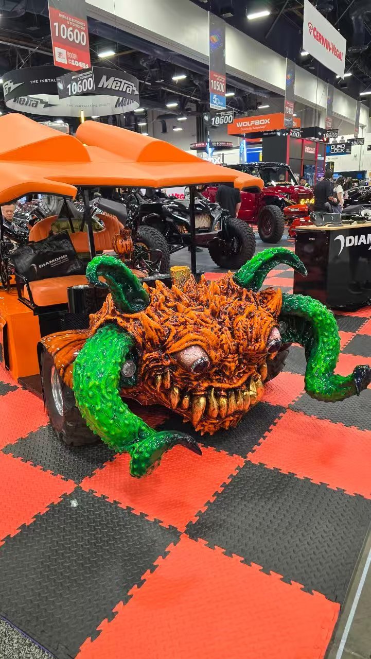
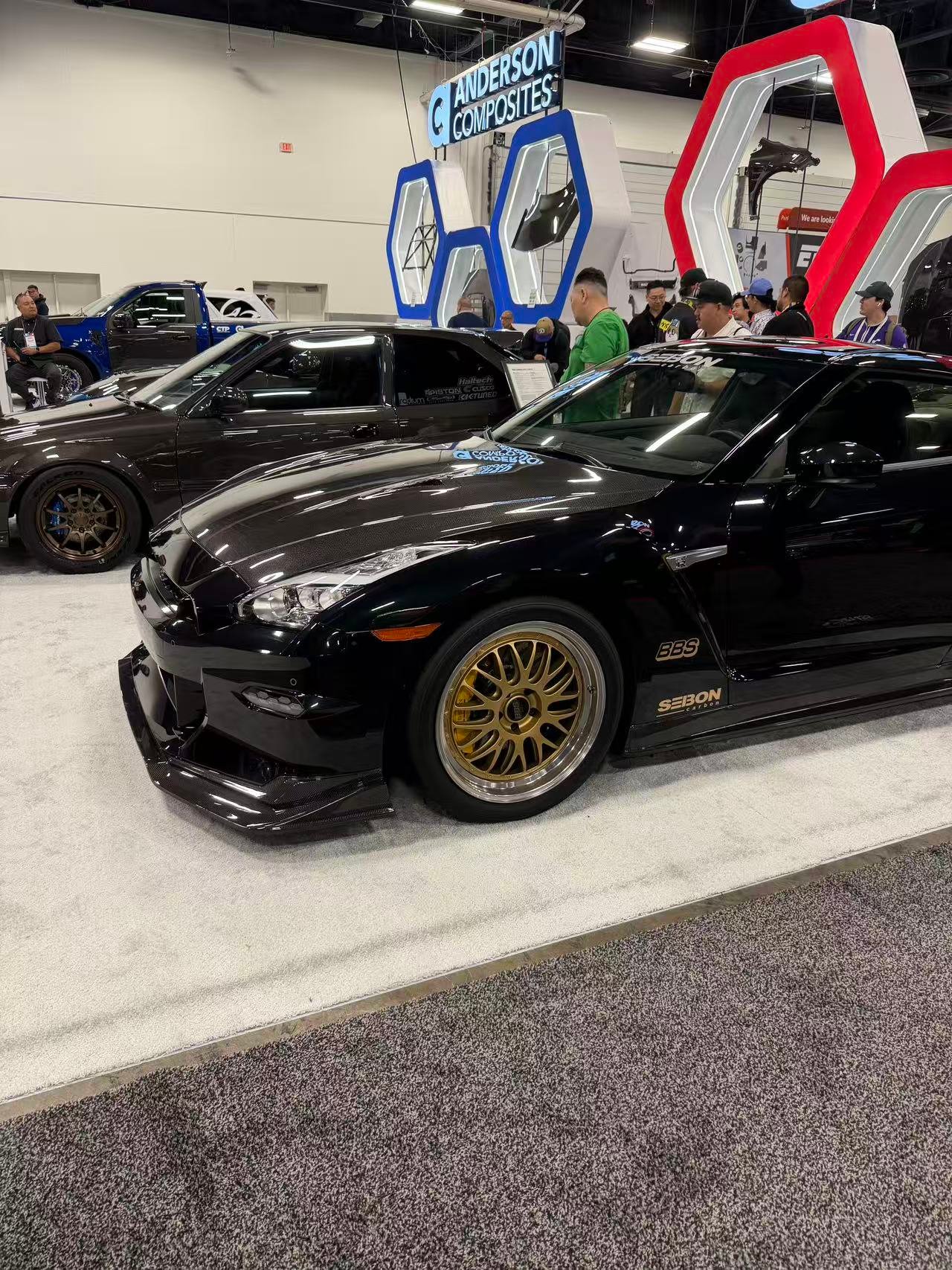
The Liberty Walk-branded show car and the orange display build make two different uses of finish and shape. For a production brief, start with the surfaces buyers can see. Mark the cosmetic faces on the drawing, decide where a tool mark or color shift would be unacceptable, and agree how appearance will be checked on samples. For a formed panel, identify the mounting faces and trim gaps that matter after assembly.
Liberty Walk-branded display car on the show floor.Custom display build with a sculpted front and vivid finish.
2. Specify UTV accessory mounting hardware around the vehicle
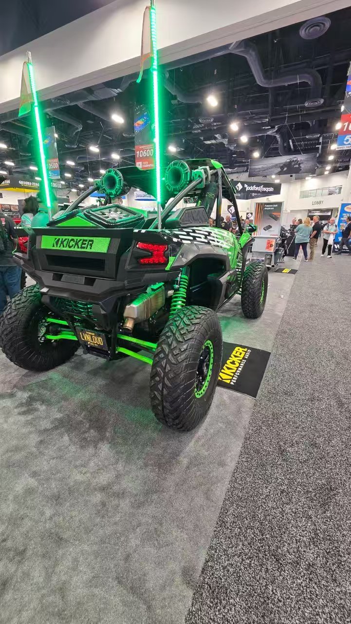
The RZR display puts cage-mounted speakers, wiring and body panels in close proximity. A bracket brief should identify the cage or tube dimensions, mounting datums, available tool access and neighboring parts. State which model years and trim variants the bracket must fit. Share expected service conditions and any vibration or load validation the buyer requires. A first article can then be checked on the intended assembly.
3. Review electronics packaging as a complete assembly
The green-lit UTV display gives a clear view of rear-mounted accessories. For a controller housing or electronics mount, specify connector clearance, cable routing, service access and any sealing or thermal requirements. Automotive CNC machining services can help assess machined interfaces for an early build. For repeat orders, evaluate sheet metal fabrication, injection molding or die casting against the drawing, order volume and tooling investment.
RZR display with cage-mounted accessories and speakers.KICKER-branded display showing rear accessory placement.
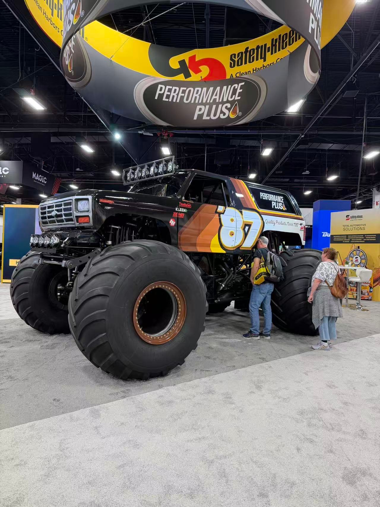
Show-floor photos provide context for the engineering discussion. Displayed vehicles and third-party brands are shown as exhibits.
Compare suppliers using the same RFQ data
For custom aftermarket auto parts manufacturing, send each supplier the same inputs and ask them to identify any assumptions in writing. Use this table to record what has been confirmed and what still needs a decision.
Buyer worksheet: inputs, supplier evidence and approval checks
Part or cost item
Data to provide
What to verify before approval
UTV accessory mounting hardware
Vehicle model, year, cage geometry, mating parts and intended service conditions
Installation fit, tool access and an agreed validation plan
Vehicle electronics housing
Connector positions, cable routing, sealing and thermal requirements
Connector clearance and the agreed inspection or test method
Cosmetic panels and brackets
CAD revision, visible faces, finish specification and acceptable appearance limits
Approved finish sample and fit on the intended assembly
Aftermarket CNC parts supplier
Critical dimensions, datum scheme, material grade and quantity breaks
Proposed process route, inspection evidence and quoted exceptions
Tooling and landed cost
Batch size, tooling scope, destination and delivery terms
Tooling ownership, recurring unit price and which delivery charges are included
Illustrative cost example: A one-time $2,000 tooling charge adds $20 per part at 100 units, $4 at 500 units and $2 at 1,000 units. Compare that tooling cost separately from unit price, freight and duties. These figures illustrate the calculation.
A memorable display earns a conversation. A supplier evaluation report should show whether the proposed manufacturing route can deliver your part, your acceptance requirements and your commercial plan.
Event setting: opportunities to meet become sourcing decisions only after part-specific review. Photograph supplied for LK MFG editorial use.
Start with a decision, then build the report
During SEMA week, purchasing teams can collect more contacts than they can meaningfully qualify. For an owner, the useful question is: what decision can we justify with the evidence we have, and what money or schedule are we putting at risk?
Choose the decision stage before assigning a score: request a quotation, authorize samples, approve a pilot, or release production. Each stage needs different evidence. A supplier may be suitable for an RFQ while still having unresolved production risks. Record that distinction instead of describing every promising contact as approved.
For the first screening conversation, use our automotive parts supplier qualification checklist. The report below turns those answers into a review procurement, engineering and management can use together.
The one-page management brief
Decision requested: exactly what the team is being asked to authorize.
Evidence available: what has been checked, by whom, against which revision.
Open risks: unresolved technical, quality, delivery and commercial questions.
Exposure: sample, tooling, inventory and payment commitments.
Next gate: what must be demonstrated before the next commitment.
Use display vehicles to sharpen your questions
A complete vehicle makes the application visible. It does not reveal who manufactured each component, which drawing was approved, or how repeat batches were inspected. Turn visual interest into a requirements conversation: where does the component mount, what does it connect to, how is it serviced, and which characteristics determine acceptance?
Use a display to ask about mounting interfaces and intended operating conditions.Appearance is one input. Fit, finish acceptance and repeatability need separate criteria.
For appearance-sensitive components, agree viewing conditions, a reference sample, acceptable variation and packaging protection. For a bracket or housing, ask engineering to identify datums, mating features and measurement methods. Do not infer strength, material grade or production capability from a photograph.
Separate observations, supplier statements and verified evidence
A useful report makes the status of every important claim visible. “Supplier says capacity is available” and “capacity assumptions reviewed against the planned release schedule” are different levels of confidence. Neither should be silently converted into a guaranteed delivery promise.
Report section
Evidence to request
Record before advancing
Technical fit
Drawing review, process route, difficult-feature comments and subcontracted steps
Approved revision, manufacturing site, reviewer and exceptions
Quality and traceability
Relevant inspection example, material records, measurement approach and corrective-action process
Acceptance criteria and how records connect to the delivered lot
Delivery readiness
Material availability, capacity assumptions, approval milestones and recovery options
Conditions behind lead time and the owner of each dependency
Commercial scope
Itemized quote, tooling, inspection, packaging, logistics and exclusions
Comparable scope, payment milestones, ownership and change rules
Keep an evidence register with document name, date, source, reviewer and status: observed, supplier-stated, verified or missing. If certification is required, check its entity, site, scope and validity through an appropriate verification route. Part-specific approval remains a separate decision.
Look beyond the visible component: assembly interfaces matter
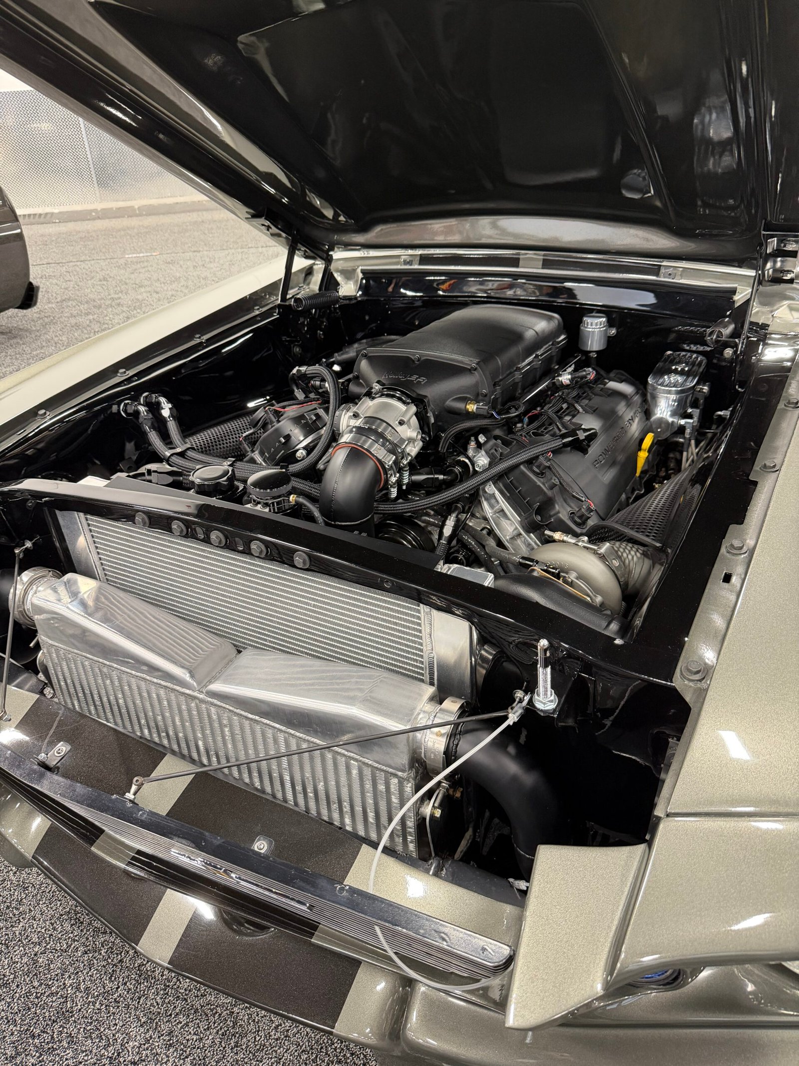
An assembly contains many interfaces. This photograph does not establish material specifications, test results or the supplier of any shown part.
The engine-bay photograph is a useful reminder that a component is rarely purchased in isolation. Ports, brackets, fasteners, hoses, clearances and access interact. Ask what the supplier needs to understand about the surrounding assembly before quoting a custom part.
For a fluid-handling or thermal component, the responsible technical team should define media compatibility, operating conditions, interfaces and any required leak or pressure test procedure. For a machined interface, agree relevant dimensions and inspection methods. The sourcing report should list requirements and approval owners rather than invent universal test limits.
Use a scorecard without hiding mandatory requirements
Suggested framework, not measured supplier data: the weights below are editable decision guidance, not an industry benchmark or a rating of the photographed exhibitors. No real supplier has been scored.
Review area
Suggested weight
Reviewer explanation
Technical and process fit
25%
Fit of the proposed route to defined part requirements
Quality and traceability
30%
Relevant inspection controls and evidence availability
Delivery and continuity
20%
Material, capacity and approval assumptions
Comparable total cost
15%
Complete equivalent scope, including exclusions
Communication and accountability
10%
Named owners, revision control and escalation
Agree scoring criteria before comparing candidates. If each area is scored from 0 to 5, weighted points equal the area weight multiplied by its score divided by 5. Keep missing evidence explicit. A high total cannot override an unresolved mandatory technical or quality requirement.
Put cost and commitment in the same view
Owners need to see the commitment attached to the recommendation. Separate one-time engineering and tooling costs from recurring unit cost. State quantity, packaging, freight basis, inspection scope and payment timing. Flag unresolved costs instead of setting them to zero.
A lower unit price may reflect a different material, quantity, finish, inspection scope or delivery assumption. Ask for alternatives as separately identified options and obtain technical approval before treating them as equivalent. See our CNC machining cost guide.
Approval gate
Permitted next step
Evidence for the next gate
RFQ review
Clarify requirements and compare equivalent quotations
Resolved scope, route and assumptions
Sample authorization
Place a bounded sample order with agreed cost and criteria
Inspection results and application-specific evaluation
Pilot authorization
Evaluate a controlled batch from the intended route
Agreed process, quality and delivery evidence
Production release
Commit within documented approval limits
Approved requirements, release authority and ongoing controls
Close the meeting with an action register
Assign each open item an owner, due date and closure evidence. Follow up with the drawing revision and decision stage. Procurement should own the commercial comparison, engineering the technical exceptions, and quality the acceptance evidence.
A recommendation can be simple: “Authorize the defined sample scope; production approval remains conditional on the listed evidence.” That is more useful than a confident ranking that obscures unanswered questions.
Frequently asked questions
Can a trade-show sample qualify a supplier?
It can justify a closer review. Qualification requires evidence for the proposed site, route, requirements and approval stage.
Should every supplier receive the same scorecard?
Use a consistent comparison basis for the same sourcing decision, retaining application-specific mandatory requirements. Agree changes before scoring.
Do the photographs show LK MFG customer projects?
The photographs were supplied for this editorial and show exhibition scenes and display vehicles. They do not identify LK MFG-made parts, customer relationships or endorsements by the pictured brands.
Turn your next conversation into a reviewable sourcing decision
Share your drawing revision, material, quantities, critical requirements and delivery target. LK MFG can discuss the information needed for your quotation or sample review.
Event context: SEMA Show 2026 runs November 3–6 in Las Vegas. Photographs provide editorial context. This report is a decision framework, not an audit of any exhibitor or evidence of LK MFG exhibiting.
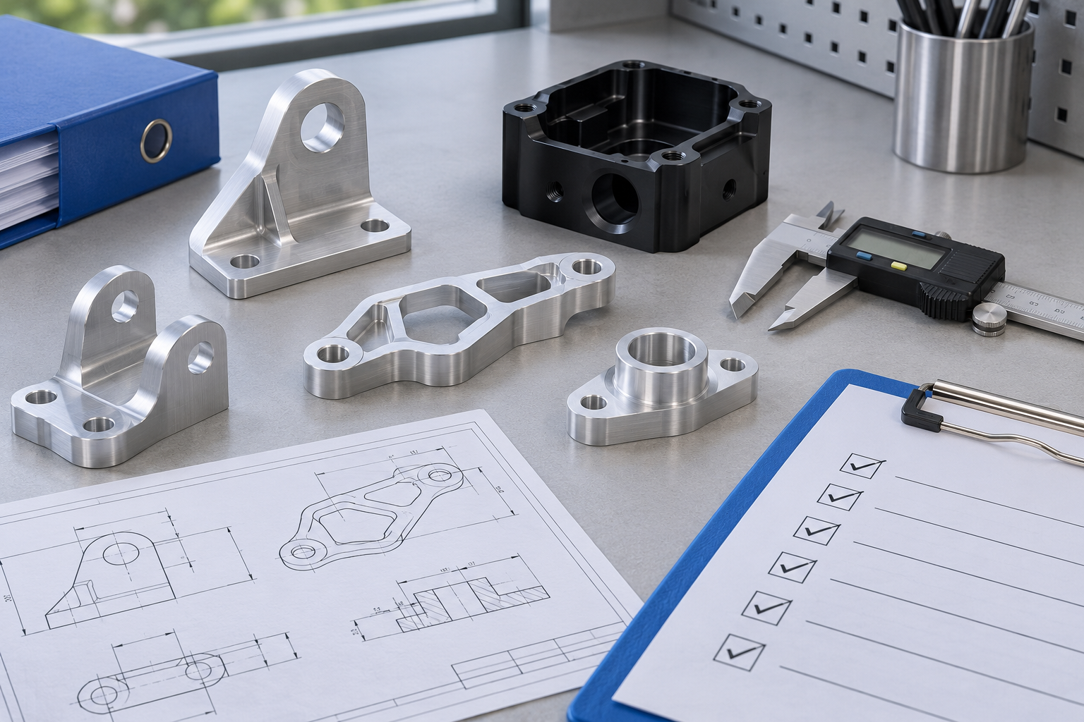
AI-generated illustrative concept, not a documentary company or customer project photograph.
A productive SEMA conversation should end with evidence to review and a defined qualification step. A booth, polished sample, or low price alone cannot establish production readiness.
Start with the part, not the supplier presentation
SEMA week brings automotive businesses into the same conversation. For a buyer, the useful outcome is a shortlist that can be tested against an actual part requirement. Before discussing price, prepare a sourcing brief: drawing revision, material grade, finish, annual forecast, first-order quantity, delivery location, and features that determine fit or function.
Separate requirements from preferences. A mounting interface may require a defined tolerance, while a hidden cosmetic surface may allow alternatives. If engineering has not approved an alternative, ask the supplier to quote it separately. This prevents a cheaper proposal from quietly changing the product.
Ask who controls each manufacturing step
Ask the prospective supplier to map the route from raw material to packaged part. Which company performs machining, forming, molding, heat treatment, finishing, inspection, and assembly? Which operations are subcontracted? Who owns corrective actions when a subcontracted operation causes a failure?
A coordinated supply chain can be appropriate. The decision depends on visibility and responsibility. Request the manufacturing location and quality contact for the proposed route. Assess both factory and trading relationships against the same evidence requirements.
Request evidence tied to your application
A showroom sample demonstrates appearance. It does not demonstrate that your dimensions, material, or production quantity can be delivered consistently. Ask for a redacted inspection report, an example of material traceability, and an explanation of revision control. Accept redaction of confidential customer information.
If a certificate is relevant, check its named entity, site, scope, validity, and verification route. A certificate does not replace part-specific approval. For safety-related or regulated applications, have the responsible technical team define validation and documentation before selection.
Check
Evidence to request
Next decision
Process fit
Proposed route and drawing comments
Technical review
Quality control
Redacted report and traceability example
Agree sample inspection
Delivery readiness
Material, capacity and approval assumptions
Conditional schedule
Commercial fit
Itemized quote and exclusions
Compare equivalent scope
Five questions for your next meeting
Which drawing features are most difficult to manufacture or inspect, and why?
What information is missing before a complete quotation can be issued?
What will be made internally and what will be subcontracted?
What sample evidence will be provided before production approval?
What happens if a shipment fails an agreed acceptance requirement?
Listen for drawing-specific answers and explicit assumptions. A relevant clarification can be more useful than an unconditional promise.
Leave with a controlled next step
Record open questions, evidence owners, and due dates. Distinguish an interesting contact from a candidate ready for sample evaluation. Send the same RFQ package to shortlisted suppliers so responses can be compared.
Authorize a sample or pilot only after its scope, price, acceptance criteria, and documentation are agreed. A successful meeting is the start of qualification. Approval follows evidence from the intended manufacturing route.
Supplier qualification: a decision report template
Method, not market research: The weights below are an editorial starting framework. They are not an industry benchmark or measured supplier results. No real supplier has been scored.
Inspection method, material records, corrective-action process
Delivery and continuity
20%
Material availability, capacity assumptions, contingency
Comparable total cost
15%
Parts, tooling, logistics, inspection and exclusions
Communication and responsibility
10%
Named owners, revision control, escalation
Score each area from 0 to 5 against criteria agreed before comparison. Calculate weighted points as weight × score ÷ 5, then sum the points. Missing evidence must remain visible. A high total cannot override a mandatory quality or technical requirement.
Complete one report for each candidate
Supplier and site
Record legal entity, manufacturing site and accountable contact.
Assessment scope
Record part number, drawing revision, quantity and approval stage.
Evidence register
Record document, source, date, reviewer and verified / supplier-stated / missing status.
Mandatory gates
List unresolved critical specifications, material identity or required validation.
Recommendation
RFQ review / sample order / pilot / production; specify approval limits.
Action register
Assign each open action an owner, due date and closure evidence.
Buyer takeaway: A well-supported sample order may be the correct next step even when production approval is not justified. Management should see both the evidence and the financial exposure before advancing.
Frequently asked questions
Does meeting a supplier at SEMA qualify it?
No. Qualification requires documented technical, quality, delivery, and commercial review for the intended part.
Should I choose only a supplier with its own factory?
Evaluate the proposed manufacturing route, visibility, and accountable organization. Ownership alone does not establish suitability.
Define your next sourcing conversation
Share your drawing revision, material, quantities, critical requirements, and delivery target with LK MFG.
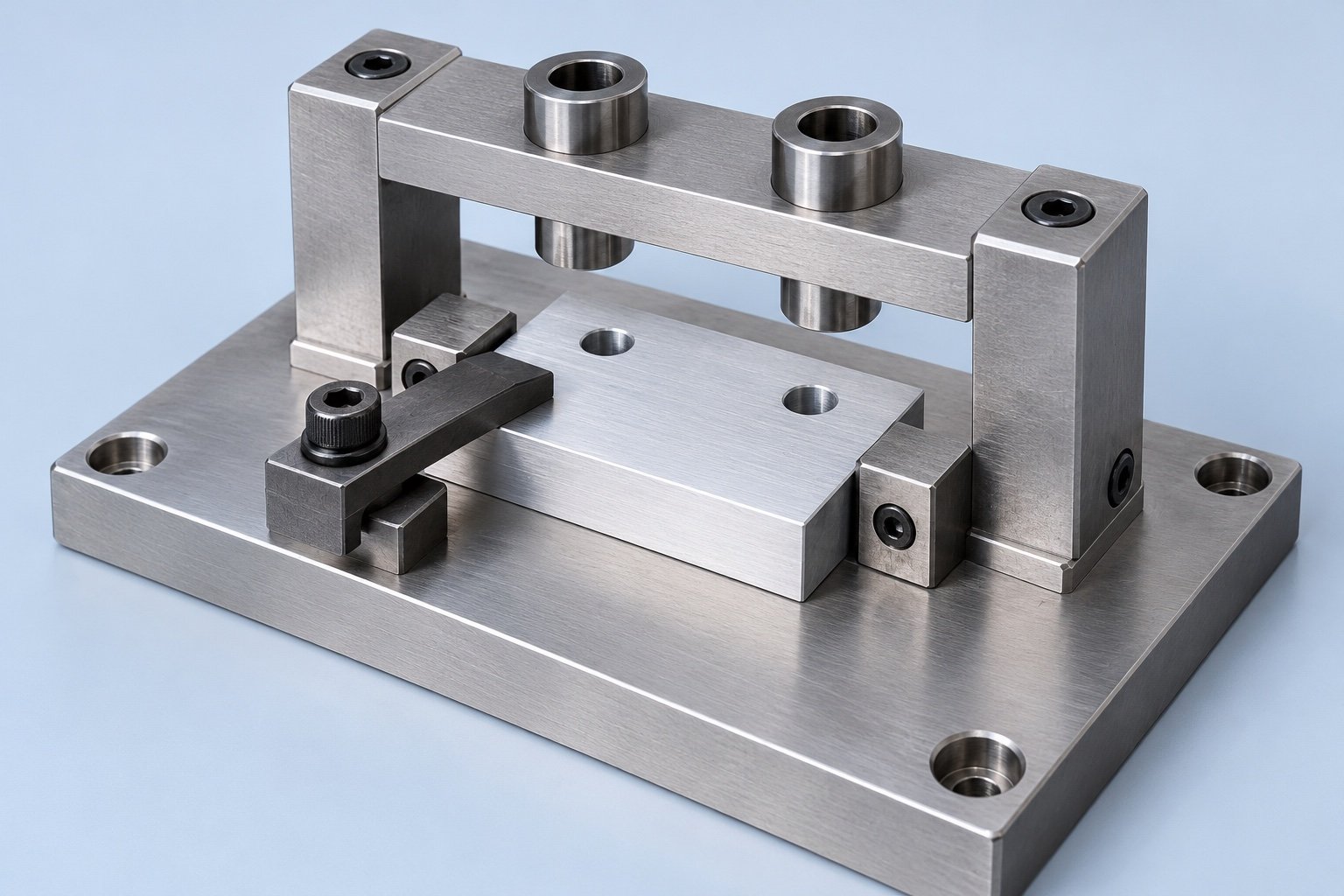
Ihre Anforderungen an Bohr- und Spannvorrichtungen sollten mit dem Arbeitsgang, dem Änderungsstand des Werkstücks und den Flächen beginnen, die seine Lage bestimmen. Eine brauchbare Beschreibung der Werkstückspannung erläutert, welche Bereiche zugänglich bleiben müssen, welche zu schützen sind und wie Ihr Team die fertige Vorrichtung abnimmt.
Eine werkzeugführende Vorrichtung, im Englischen „jig“, positioniert und hält üblicherweise ein Werkstück und führt zugleich das Schneidwerkzeug. Eine Spannvorrichtung, „fixture“, positioniert und hält das Werkstück, während die Maschine oder ein anderes System die Werkzeugbahn steuert. Beispielsweise kann eine Bohrvorrichtung Führungsbuchsen verwenden; bei einer Fräsvorrichtung übernimmt die Maschine die Führung des Fräsers. Diesen Unterschied beschreibt KEYENCE in seiner Erläuterung zu Vorrichtungen für Fertigung und Prüfung.
Legen Sie fest, was die Vorrichtung kontrollieren muss
Beginnen Sie mit der Aufgabe Ihrer Vorrichtung, statt eine bestimmte Form anzufragen. Vielleicht muss Ihr Team ein wiederkehrendes Lochbild bohren, mehrere Seiten zum Fräsen freihalten, eine Baugruppe beim Einsetzen von Befestigungselementen abstützen oder ein Teil für die Prüfung immer gleich ausrichten. Jede Aufgabe stellt andere Anforderungen an Zugänglichkeit und Abnahme.
Frage
Beispiel: werkzeugführende Vorrichtung
Beispiel: Spannvorrichtung
Was führt das Werkzeug?
Eine Bohrbuchse führt den Bohrer mechanisch.
Die Maschine steuert die Bewegung des Fräsers.
Was muss zugänglich sein?
Das Werkzeug muss in die Führung eintreten und sie wieder verlassen können.
Der vorgesehene Fräser, Messtaster oder das Montagewerkzeug muss die erforderlichen Merkmale erreichen.
Was gehört in Ihre Beschreibung?
Anforderungen an die Bohrungen, Werkzeugdaten und Anforderungen an die Wartung der Buchsen.
Aufspannlage, Positioniermerkmale und erforderlicher Arbeitsraum.
Die Bezeichnung allein legt die Konstruktion nicht fest. Fügen Sie eine markierte Zeichnung oder Aufspannskizze des vorgesehenen Arbeitsgangs bei und bitten Sie den Vorrichtungshersteller, Annahmen vor der Fertigung offenzulegen.
Unterscheiden Sie Positionieren, Abstützen und Spannen
Positionierelemente bestimmen die Lage des Teils. Auflagen nehmen unter dem Werkstück Kräfte auf; Spannelemente halten es an den Auflagen. Die Grundsätze der Vorrichtungskonstruktion von Carr Lane erläutern den Zusammenhang zwischen Positionieren und Spannen sowie die Vermeidung einer Überbestimmung. Die Hinweise zur Werkstückabstützung beschreiben außerdem, wie unzureichende Abstützung eine Verformung des Teils unter Schnittkräften zulassen kann.
Kennzeichnen Sie für Ihre Prüfung, welche Zeichnungsflächen oder Bohrungen die Bezüge bilden, welche Merkmale am eingehenden Teil variieren dürfen und wo Spannelemente anliegen dürfen. Überlassen Sie es dem Lieferanten nicht, eine bequem erreichbare Rohkante als funktionalen Bezug anzunehmen. Wenn eine Sichtfläche keine Spuren erhalten darf, benennen Sie dies und vereinbaren Sie ihren Schutz.
Prüfen Sie die Zugänglichkeit vor der Modellfreigabe
Fordern Sie eine Aufspannansicht an, in der Werkstück, Spannelemente und vorgesehene Werkzeuge gemeinsam dargestellt sind. Prüfen Sie den Zugang zu jedem erforderlichen Merkmal, den Platz für den Werkzeugwechsel und den Weg zum Einlegen und Entnehmen des Teils. Ein ansprechend dargestelltes leeres Vorrichtungsmodell kann Probleme bei eingelegtem Werkstück verdecken.
Beziehen Sie das Prüfverfahren in diese Abstimmung ein. Ein einfach zu bearbeitendes Merkmal lässt sich bei gespanntem Teil möglicherweise nur schwer antasten. Ihr Abnahmeplan sollte festlegen, welche Prüfungen in der Vorrichtung und welche nach dem Entnehmen stattfinden. Die Vorrichtungsfreigabe darf die Zeichnungsanforderungen an das fertige Teil nicht stillschweigend ersetzen.
Wählen Sie Werkstoffe für die tatsächliche Einsatzumgebung
Nennen Sie dem Lieferanten Kühlschmierstoff, Reinigungsverfahren, Kontaktflächen sowie mögliche Temperatur- oder Chemikalieneinwirkungen. Kennzeichnen Sie austauschbare Teile, etwa Kontaktauflagen, Positionierelemente oder Bohrbuchsen. Wenn Wartung wichtig ist, fordern Sie eine abgestimmte Ersatzteilliste an.
Bearbeitete Metallteile, Kunststoff-Kontaktelemente und gedruckte Bauteile können je nach Belastung, Verschleiß, Umgebung und erforderlicher Genauigkeit jeweils sinnvoll sein. Ein Werkstoffname allein reicht für die Freigabe einer Produktionsvorrichtung nicht aus. Fragen Sie nach den Nachweisen, die den vorgeschlagenen Werkstoff für Ihren konkreten Arbeitsgang stützen. Bei jeder Änderung eines Positionier- oder Kontaktelements ist dessen Einfluss auf das Werkstück zu prüfen.
Nutzen Sie einen Versuch für eine konkrete Fragestellung
Betrachten Sie als Beispiel ein Winkelbauteil. Ihre Zeichnung legt die Montagefläche und zwei Bohrungen als funktionale Bezüge fest; die Außenkontur des eingehenden Rohlings variiert jedoch. Bei der Vorrichtungsprüfung ist zu klären, wie der Winkel ohne Bezug auf diese Kontur positioniert wird, wo gespannt werden darf und ob der Fräser die erforderlichen Flächen erreicht.
Ein sinnvoller Versuch prüft diese vereinbarten Fragen anhand repräsentativer Teile. Dokumentieren Sie Einlegeorientierung, Sitzkontrollen, Zugangsprobleme und vereinbarte Messergebnisse. Wenn mehrere Eingangszustände zulässig sind, benennen Sie die im Versuch vertretenen Zustände. Dieses Beispiel beschreibt ein Prüfverfahren und verspricht weder eine Toleranz noch eine Taktzeit oder ein Produktionsergebnis.
Senden Sie eine vollständige Anfrage für Ihre Vorrichtung
Aktuelles CAD-Modell und Zeichnung des Teils einschließlich Änderungsstand und relevanter Bezüge.
Arbeitsgang, Schnittstelle zur Maschine oder zum Arbeitsplatz und verfügbarer Arbeitsraum.
Zustand des eingehenden Teils, zulässige Abweichungen und zu schützende Bereiche.
Vorgesehener Einsatz, Beladeverfahren und Einschränkungen bei der Handhabung.
Zugänge für Werkzeuge, Messtaster, Befestigungselemente oder Montagearbeiten, die frei bleiben müssen.
Abnahmeprüfungen, erforderliche Aufzeichnungen und Wartungserwartungen.
Kennzeichnen Sie noch offene Angaben ausdrücklich. Trennen Sie bereits freigegebene Anforderungen von Vorschlägen, die der Lieferant bewerten soll. Ihre bestehende Checkliste für CNC-Bearbeitungsanfragen hilft bei der Zusammenstellung der Zeichnungsunterlagen; die Vorrichtungsbeschreibung ergänzt die Anforderungen an Aufspannung und Werkstückhaltung.
Klären Sie diese Fragen vor der Bestellung
Benötigt jede CNC-Aufspannung eine Sondervorrichtung?
Besprechen Sie zunächst Standardspannmittel und benennen Sie anschließend das verbleibende Problem bei Zugang, Abstützung oder wiederholtem Einlegen. Bitten Sie den Lieferanten zu erläutern, weshalb eine Sondervorrichtung für Ihr Teil und Ihren Auftragsumfang geeignet ist.
Kann ein gedrucktes Bauteil eine Metallvorrichtung ersetzen?
Das erfordert eine anwendungsspezifische Prüfung. Geben Sie Einsatzbedingungen und Abnahmeanforderungen an und bewerten Sie das vorgeschlagene Bauteil samt Validierungsplan. Genehmigen Sie einen Austausch nicht allein aufgrund einer Werkstoffbezeichnung.
Welche Unterlagen sollten zur Lieferung gehören?
Vereinbaren Sie vor der Bestellung den Änderungsstand der Vorrichtung, Aufspannanweisungen, Abnahmeaufzeichnungen und Angaben zu austauschbaren Komponenten. Ordnen Sie diese dem Änderungsstand des Werkstücks zu, damit spätere Zeichnungsänderungen an der richtigen Vorrichtung geprüft werden können.
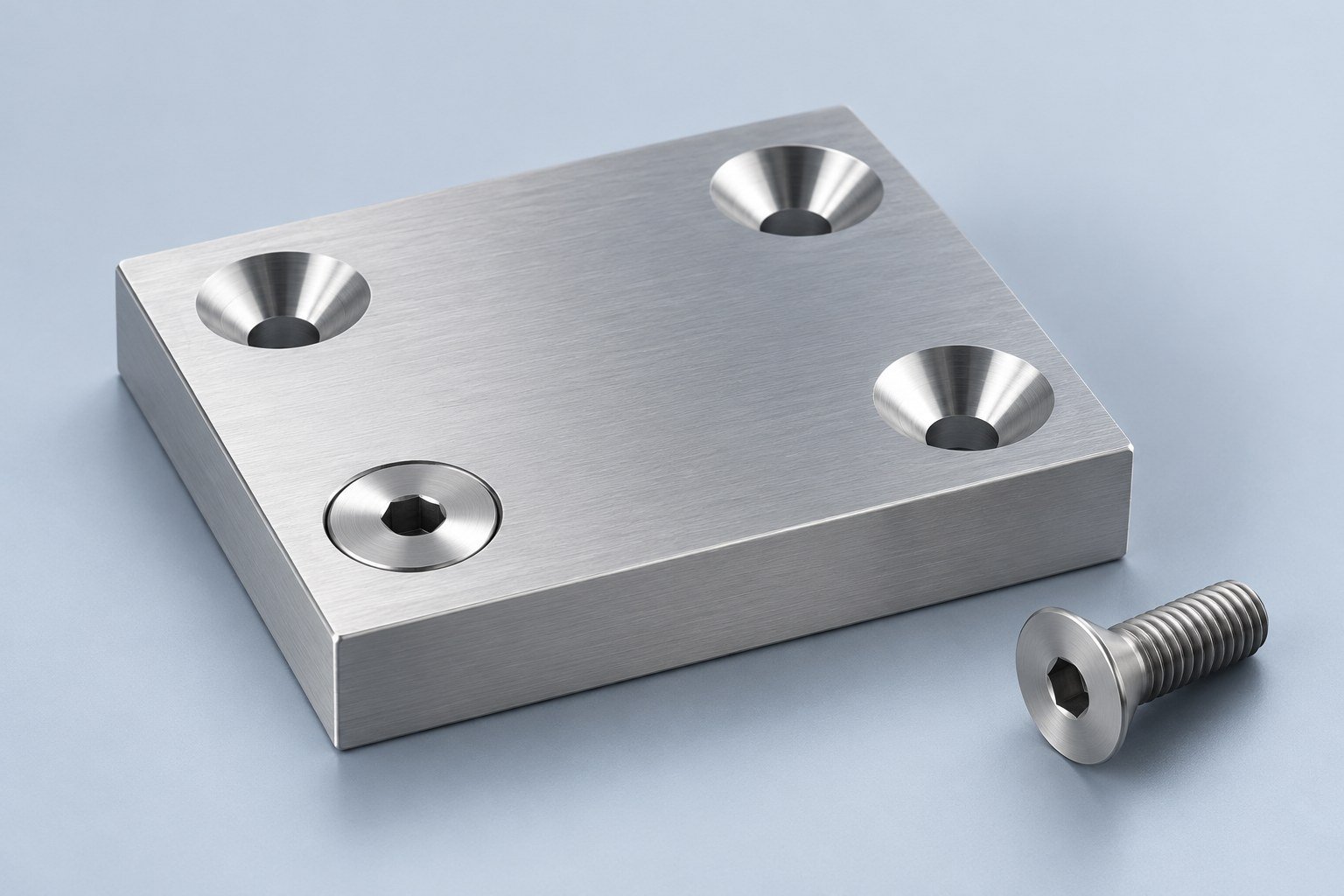
يوفر الثقب الغاطس مقعدًا مخروطيًا لمثبت ذي رأس غاطس. بالنسبة إلى قطعتك، يجب التأكد من استقرار البرغي المختار عند الارتفاع المطلوب ومن بقاء مادة كافية لدعم رأسه. وقد يحتاج ثقب يبدو صحيحًا في نموذج CAD إلى توضيح إضافي إذا أغفل الرسم الزاوية أو القطر أو جهة المقعد أو الحالة بعد التشطيب.
يوضح هذا الدليل القرارات التي ينبغي إدراجها في الرسم وطلب عرض السعر. وهو أداة لمراجعة التصميم؛ فمواصفة المثبت المعتمدة والرسم هما المرجع لتحديد الميزة المطلوب تصنيعها.
ما هو الثقب الغاطس؟
يحتوي الثقب الغاطس على توسعة مخروطية عند الفتحة، تشكل مقعدًا لبرغي أو برشام متوافق ذي رأس غاطس. أما التجويف الأسطواني للرأس فله جدران أسطوانية وقاع مسطح. وقد تبدو شطفة إزالة الحافة الحادة مخروطية أيضًا، لكن ملاحظة عامة لإزالة الرايش لا تحدد مقعد المثبت بالكامل.
الميزة
شكل المقعد
ما يجب توضيحه في الرسم
غاطس مخروطي
مخروطي
قطر الثقب والقطر الأكبر والزاوية الكلية وجهة المقعد
تجويف أسطواني للرأس
قاع مسطح وجدران أسطوانية
قطر الثقب وقطر التجويف وعمقه
إزالة حدة الحافة
شطفة صغيرة أو نصف قطر
حالة الحافة المسموح بها؛ لا تفترض أنها تحدد مقعد البرغي أيضًا
طابق الزاوية الكلية مع المثبت
زاوية الغاطس هي الزاوية الكلية المحصورة للمخروط. تتوافر أدوات شائعة بزوايا 82° و90°. ويربط مصنع الأدوات Thürmer زاوية 90° بالبراغي المترية الشائعة ذات الرأس الغاطس، وزاوية 82° بالبراغي الشائعة ذات المقاسات بالبوصة والرأس الغاطس. استخدم ذلك كنقطة بداية ثم تحقق من المواصفة الفعلية للمثبت؛ فقد تتطلب المثبتات الخاصة زاوية مختلفة.
لا تختَر الزاوية اعتمادًا على قطر القلاوظ وحده. زوّد فريق التصنيع بتعيين البرغي أو رسم المورد، مع متطلبات الطلاء أو شكل الرأس الخاص. يؤدي اختلاف الزاوية إلى تغيير تلامس الرأس مع المقعد؛ ولا تضمن زيادة القطر وحدها ملاءمة المقعد.
حدّد الثقب بتوصيف كامل في الرسم
يصف نموذج CAD الشكل، بينما يحدد الرسم الخاضع للتحكم الأبعاد ومتطلبات القبول. أدرج ما يلي:
قطر ثقب الخلوص، وما إذا كان نافذًا أم غير نافذ.
القطر الأكبر للغاطس والزاوية الكلية المحصورة، مع التفاوتات المطبقة.
الوجه المطلوب للغاطس، خصوصًا عندما يمكن تفسير أي من الجهتين كجهة دخول.
عدد الميزات المتطابقة ومواقعها.
موضع الرأس المطلوب: بمحاذاة السطح أو أسفله أو في حالة أخرى محددة.
المادة والتشطيب، وما إذا كان القبول مطلوبًا قبل التشطيب أم بعده.
توضح ملاحظة تخطيطية مثل «ثقب نافذ ⌀6.6؛ غاطس ⌀12 × 90°، هذه الجهة» نوع المعلومات المطلوبة. هذه الأبعاد التوضيحية ليست توصية لبرغي معين. اختر القيم وفق المثبت الفعلي وتجميع الأجزاء ومتطلبات التصميم، واتبع معيار الرسم المعتمد للرموز وطريقة العرض.
استخدم حساب العمق للتحقق الهندسي
بالنسبة إلى مقعد مخروطي مثالي، يمثل D القطر الأكبر، ويمثل d قطر الجزء الأسطواني من الثقب، وتمثل θ الزاوية الكلية المحصورة. ويكون الارتفاع المحوري للتوسعة المخروطية:
h = (D − d) / [2 × tan(θ / 2)]
على سبيل المثال، عند D = 12 mm وd = 6.6 mm وθ = 90°، تكون h = 2.7 mm. هذا مثال هندسي، وليس إعدادًا لعمق الأداة أو ضمانًا لملاءمة البرغي. قد يؤثر السطح المسطح عند طرف الأداة وشكل الرأس وشطفات الحواف وتشطيب السطح في النتيجة الفعلية. أبقِ الأبعاد الحاكمة في الرسم مرجعًا، ولا تضف متطلبات متعارضة للقطر والعمق.
راجع المادة المتبقية والميزات المجاورة
قارن شكل المقعد المخروطي بسماكة الجدار المحلية. إذا اقترب المقعد من الوجه المقابل، فراجع مع المهندس مقدار الدعم المتبقي وخطر الاختراق. قد تتطلب الصفائح الرقيقة مثبتًا آخر أو ميزة مشكلة بدلًا من غاطس عميق مشغّل بالقطع. تحتاج هذه البدائل إلى موافقة؛ ولا تُعد بدائل إنتاجية قابلة للتبادل تلقائيًا.
راجع أيضًا المسافة إلى الحافة والثقوب والثنيات والجيوب المجاورة، والمساحة اللازمة لوصول الأداة والمثبت. فقد يخفي المسقط العلوي الخالي من العوائق تعارضًا مع جيب في الوجه الخلفي. ويمكن لمقطع عرضي أن يسهّل مراجعة هذه العلاقة.
اتفق على طريقة فحص المقعد
يجب أن يتبع الفحص معايير القبول في الرسم. فالقطر الأكبر والزاوية الكلية والموقع تصف جوانب مختلفة من الميزة. ويمكن لبرغي نموذجي أن يساعد في إظهار استقرار الرأس أثناء التجميع عندما يكون هذا الفحص متفقًا عليه، لكنه لا يتحقق وحده من جميع متطلبات الأبعاد.
بالنسبة إلى عينة أولى وظيفية، حدّد المثبت الفعلي وتجميع الأجزاء المقابل المستخدمين في المراجعة. وضّح ما إذا كان التحقق من محاذاة الرأس يتم بعد الطلاء، وحدّد مقدار انخفاض الرأس أو بروزه المسموح به. وإذا كانت عيوب السطح أو الرايش أو آثار اهتزاز الأداة قد تؤثر في التجميع، فحدّد حالة السطح المطلوبة قبل الإنتاج.
ما الذي ترسله في طلب عرض سعر لقطعة ذات ثقوب غاطسة؟
أرسل نموذج CAD الحالي وإصدار الرسم، والمادة والتشطيب، وكميات الطلب الأول والطلبات المتكررة، ومواصفة المثبت، ومتطلبات المقعد والفحص الحرجة. حدّد القرارات غير المحسومة بدلًا من ترك المورد يستنتجها. يمنح ذلك فريقك أساسًا أوضح لمقارنة عروض الأسعار واعتماد الإنتاج الأول.
يمكن تصنيع الغاطس بأداة قطع مخروطية، لكن وظيفته هنا هي توفير مقعد محدد لمثبت. لا تفترض أن ملاحظة عامة للشطف أو إزالة حدة الحافة تحدد قطر المقعد وزاويته وموضع الرأس.
هل يمكن الاختيار بين 82° و90° بالنظر فقط؟
لا. تحقق من مواصفة المثبت والزاوية الكلية المطلوبة. لا يثبت تشابه الرؤوس والأدوات أن زواياها متطابقة.
هل محاذاة الرأس مع السطح تثبت صحة الثقب بالكامل؟
لا. استقرار الرأس فحص وظيفي واحد. وقد يتطلب الرسم أيضًا فحص القطر والزاوية والموقع وميزات أخرى بالأبعاد.
Een verzonken gat biedt een conische zitting voor een bevestigingsmiddel met verzonken kop. Voor uw onderdeel is de vraag of de gekozen schroef op de bedoelde hoogte komt te liggen en of er voldoende materiaal overblijft om de kop te ondersteunen. Een gat dat er in CAD correct uitziet, kan nog verduidelijking vereisen als de tekening de hoek, diameter, zittingzijde of toestand na afwerking niet vermeldt.
Deze gids beschrijft welke keuzes u in uw tekening en offerteaanvraag opneemt. Het is een hulpmiddel voor ontwerpbeoordeling; de goedgekeurde specificatie van het bevestigingsmiddel en uw tekening bepalen de te vervaardigen geometrie.
Wat is een verzonken gat?
Een verzonken gat heeft een conische verwijding bij de opening. Deze vormt een zitting voor een passende schroef of klinknagel met verzonken kop. Een cilindrische verzinking heeft rechte cilindrische wanden en een vlakke bodem. Ook een afschuining om een scherpe rand te breken kan conisch lijken, maar een algemene ontbraamnotitie definieert de zitting van een bevestigingsmiddel niet volledig.
Kenmerk
Vorm van de zitting
Wat uw tekening moet verduidelijken
Conische verzinking
Conisch
Gatdiameter, grootste diameter, ingesloten hoek en zittingzijde
Cilindrische verzinking
Vlakke bodem en cilindrische wanden
Gatdiameter, diameter van de uitsparing en diepte van de uitsparing
Randbreking
Kleine afschuining of radius
Toegestane randtoestand; neem niet aan dat hiermee ook de schroefzitting is gedefinieerd
Stem de ingesloten hoek af op uw bevestigingsmiddel
De verzinkhoek is de volledige ingesloten hoek van de kegel. Veelgebruikte gereedschappen zijn verkrijgbaar met hoeken van 82° en 90°. Gereedschapsfabrikant Thürmer koppelt 90° aan gangbare metrische schroeven met verzonken kop en 82° aan gangbare schroeven in inchmaten met verzonken kop. Gebruik dit als uitgangspunt en controleer vervolgens de werkelijke specificatie van het bevestigingsmiddel. Speciale bevestigingsmiddelen kunnen een andere hoek vereisen.
Kies de hoek niet uitsluitend op basis van de schroefdraaddiameter. Geef uw productieteam de schroefaanduiding of de leverancierstekening, samen met eventuele eisen aan coating of speciale kopvorm. Een afwijkende hoek verandert het contact tussen kop en zitting; alleen de diameter vergroten zorgt niet automatisch voor een passende zitting.
Definieer het gat met een volledige tekeningaanduiding
Uw CAD-model beschrijft de vorm, terwijl de beheerde tekening de afmetingen en acceptatie-eisen vastlegt. Vermeld:
De diameter van het doorvoergat en of het gat doorlopend of blind is.
De grootste diameter van de verzinking en de volledige ingesloten hoek, met de geldende toleranties.
Het vlak waarop de verzinking moet komen, vooral als beide zijden als ingang kunnen worden uitgelegd.
Het aantal en de posities van de overeenkomstige kenmerken.
De vereiste koppositie: vlak met het oppervlak, onder het oppervlak of een andere gespecificeerde toestand.
Het materiaal, de afwerking en of de acceptatie vóór of na die afwerking geldt.
Een schematische notitie zoals ‘⌀6,6 DOORLOPEND; verzinking ⌀12 × 90°, deze zijde’ laat zien welke informatie nodig is. Deze voorbeeldmaten zijn geen aanbeveling voor een specifieke schroef. Kies waarden op basis van uw werkelijke bevestigingsmiddel, onderdelenpakket en ontwerpvereisten. Volg uw tekennorm voor symbolen en presentatie.
Gebruik de diepteberekening als geometrische controle
Voor een ideale conische zitting is D de grootste diameter, d de diameter van het cilindrische gat en θ de volledige ingesloten hoek. De axiale hoogte van de conische verwijding is:
h = (D − d) / [2 × tan(θ / 2)]
Bijvoorbeeld: met D = 12 mm, d = 6,6 mm en θ = 90° is h = 2,7 mm. Dit is een geometrisch voorbeeld, geen instelling voor de gereedschapsdiepte of garantie voor de passing van een schroef. Een vlak aan de gereedschapspunt, de kopgeometrie, randbrekingen en de oppervlakteafwerking kunnen het werkelijke resultaat beïnvloeden. Laat de bepalende maten op de tekening leidend blijven en voeg geen tegenstrijdige eisen voor diameter en diepte toe.
Controleer het resterende materiaal en nabije kenmerken
Vergelijk de geometrie van de conische zitting met de plaatselijke wanddikte. Als de zitting de tegenoverliggende zijde nadert, bespreek dan met uw engineer de resterende ondersteuning en het risico op doorbraak. Dun plaatmateriaal kan een ander bevestigingsmiddel of een gevormd kenmerk vereisen in plaats van een diep verspaande verzinking. Voor deze alternatieven is goedkeuring nodig; het zijn geen onderling uitwisselbare productievervangingen.
Controleer ook de afstand tot de rand, aangrenzende gaten, buigingen, kamers en de benodigde toegang voor gereedschap en bevestigingsmiddel. Een vrij bovenaanzicht kan een conflict met een kamer aan de achterzijde verbergen. Een doorsnede kan deze relatie gemakkelijker controleerbaar maken.
Spreek af hoe de zitting wordt gecontroleerd
De inspectie moet de acceptatiecriteria op de tekening volgen. De grootste diameter, ingesloten hoek en positie beschrijven verschillende aspecten van het kenmerk. Een voorbeeldschroef kan helpen om de zitting bij montage te tonen wanneer die controle is afgesproken, maar verifieert niet zelfstandig alle maateisen.
Leg voor een functioneel eerste artikel het werkelijke bevestigingsmiddel en het bijbehorende onderdelenpakket voor de beoordeling vast. Geef aan of de vlakligging na coating wordt gecontroleerd en definieer de toegestane verzonken of uitstekende positie. Als oppervlaktedefecten, bramen of trillingssporen de montage kunnen beïnvloeden, maak dan vóór productie duidelijk welke oppervlaktetoestand vereist is.
Wat u opneemt in de offerteaanvraag voor uw verzonken onderdeel
Stuur het actuele CAD-model en de tekeningrevisie, materiaal en afwerking, eerste en herhaalaantallen, de specificatie van het bevestigingsmiddel en de kritische zitting- en inspectie-eisen. Markeer openstaande keuzes in plaats van uw leverancier deze te laten afleiden. Zo heeft uw team een duidelijkere basis om offertes te vergelijken en de eerste productie goed te keuren.
Een verzinking kan met conisch snijgereedschap worden gemaakt, maar heeft hier de functie van een gespecificeerde zitting voor een bevestigingsmiddel. Neem niet aan dat een algemene afschuinings- of randbreeknotitie de diameter, hoek en koppositie van die zitting definieert.
Kan ik op het oog kiezen tussen 82° en 90°?
Nee. Controleer de specificatie van het bevestigingsmiddel en de vereiste ingesloten hoek. Gelijkende koppen en gereedschappen bewijzen niet dat hun hoeken overeenkomen.
Bewijst een vlakliggende kop dat het hele gat correct is?
Nee. De zitting is één functionele controle. Uw tekening kan daarnaast maatcontroles van diameter, hoek, positie en andere kenmerken vereisen.
Un foro svasato offre una sede conica a un elemento di fissaggio a testa svasata. Per il vostro pezzo, occorre verificare che la vite scelta si trovi all’altezza prevista e che rimanga materiale sufficiente a sostenerne la testa. Un foro che sembra corretto nel modello CAD può ancora richiedere chiarimenti se il disegno omette l’angolo, il diametro, il lato della sede o la condizione di finitura.
Questa guida spiega quali decisioni includere nel disegno e nella richiesta di preventivo. È un supporto alla revisione del progetto; la specifica approvata dell’elemento di fissaggio e il disegno determinano la caratteristica da produrre.
Che cos’è un foro svasato?
Un foro svasato presenta un allargamento conico all’imbocco. Il cono costituisce la sede di una vite o di un rivetto a testa svasata compatibile. Una lamatura presenta invece una cavità cilindrica a fondo piano. Anche uno smusso per eliminare uno spigolo può apparire conico, ma una nota generale di sbavatura non definisce completamente la sede di un elemento di fissaggio.
Caratteristica
Forma della sede
Che cosa chiarire nel disegno
Svasatura
Conica
Diametro del foro, diametro maggiore, angolo incluso e lato della sede
Lamatura
Fondo piano e pareti cilindriche
Diametro del foro, diametro della lamatura e profondità della lamatura
Eliminazione dello spigolo
Piccolo smusso o raggio
Condizione ammessa dello spigolo; non presumere che definisca anche la sede della vite
Adattate l’angolo incluso all’elemento di fissaggio
L’angolo di svasatura è l’angolo totale incluso del cono. Tra gli utensili comuni vi sono versioni a 82° e 90°. Il produttore di utensili Thürmer associa i 90° alle comuni viti metriche a testa svasata e gli 82° alle comuni viti in pollici a testa svasata. Consideratelo un punto di partenza, quindi verificate la specifica effettiva della vite. Gli elementi di fissaggio speciali possono richiedere un angolo diverso.
Non scegliete l’angolo soltanto in base al diametro della filettatura. Fornite al team di produzione la designazione della vite o il disegno del fornitore, insieme ai requisiti di rivestimento o di testa speciale. Una differenza di angolo modifica il contatto tra testa e sede; aumentare soltanto il diametro non garantisce un appoggio compatibile.
Definite il foro con un’indicazione completa sul disegno
Il modello CAD comunica la forma, mentre il disegno controllato comunica le dimensioni e i requisiti di accettazione. Includete:
Il diametro del foro di passaggio e l’indicazione di foro passante o cieco.
Il diametro maggiore della svasatura e l’angolo totale incluso, con le tolleranze applicabili.
La faccia su cui realizzare la svasatura, soprattutto se entrambe potrebbero essere interpretate come faccia d’ingresso.
Il numero e le posizioni delle caratteristiche uguali.
La posizione richiesta della testa: a filo, sotto la superficie o in un’altra condizione specificata.
Il materiale, la finitura e l’indicazione se l’accettazione si applica prima o dopo tale finitura.
Una nota schematica come «⌀6,6 PASSANTE; svasatura ⌀12 × 90°, questa faccia» illustra le informazioni necessarie. Queste dimensioni di esempio non sono una raccomandazione per una vite specifica. Scegliete i valori in base all’elemento di fissaggio effettivo, all’insieme dei componenti e ai requisiti di progettazione. Seguite la norma di disegno applicabile per simboli e presentazione.
Usate il calcolo della profondità come controllo geometrico
Per una sede conica ideale, D indica il diametro maggiore, d il diametro del foro cilindrico e θ l’angolo totale incluso. L’altezza assiale dell’allargamento conico è:
h = (D − d) / [2 × tan(θ / 2)]
Per esempio, con D = 12 mm, d = 6,6 mm e θ = 90°, h = 2,7 mm. È un esempio geometrico, non un’impostazione della profondità di taglio né una garanzia di accoppiamento della vite. La superficie piana sulla punta dell’utensile, la geometria della testa, l’eliminazione degli spigoli e la finitura superficiale possono influire sul risultato reale. Mantenete autorevoli le dimensioni che definiscono il disegno, evitando requisiti di diametro e profondità in conflitto.
Controllate il materiale residuo e le caratteristiche vicine
Confrontate la geometria della sede conica con lo spessore locale della parete. Se la sede si avvicina alla faccia opposta, riesaminate con il vostro progettista il sostegno residuo e il rischio di sfondamento. Una lamiera sottile può richiedere un fissaggio diverso o una caratteristica ottenuta per deformazione anziché una svasatura profonda lavorata per asportazione. Queste alternative richiedono approvazione; non sono sostituzioni produttive intercambiabili.
Controllate anche la distanza dal bordo, i fori adiacenti, le pieghe, le tasche e l’accesso necessario per utensile e fissaggio. Una vista dall’alto apparentemente libera può nascondere un’interferenza con una tasca sulla faccia posteriore. Una sezione può rendere più semplice verificare questa relazione.
Concordate come controllare la sede
L’ispezione deve seguire i criteri di accettazione del disegno. Diametro maggiore, angolo incluso e posizione descrivono aspetti diversi della caratteristica. Una vite campione può aiutare a mostrare l’appoggio durante il montaggio, se tale controllo è concordato, ma non verifica autonomamente tutti i requisiti dimensionali.
Per un primo articolo funzionale, identificate il fissaggio effettivo e l’insieme dei componenti accoppiati utilizzati nella revisione. Specificate se la complanarità della testa viene controllata dopo il rivestimento e definite eventuali incassi o sporgenze ammessi. Se danni superficiali, bave o segni di vibrazione possono influire sul montaggio, chiarite la condizione superficiale richiesta prima della produzione.
Che cosa includere nella richiesta di preventivo per il pezzo svasato
Inviate il modello CAD e la revisione corrente del disegno, materiale e finitura, quantità iniziali e ricorrenti, specifica del fissaggio e requisiti critici di appoggio e ispezione. Evidenziate le scelte ancora aperte, senza lasciare che il fornitore debba dedurle. Il vostro team avrà così una base più chiara per confrontare i preventivi e approvare la prima produzione.
Domande da risolvere prima di autorizzare la produzione
Una svasatura è la stessa cosa di uno smusso?
Una svasatura può essere realizzata con un utensile conico, ma qui la sua funzione è quella di una sede specificata per un fissaggio. Non si deve presumere che una nota generale di smusso o eliminazione degli spigoli definisca diametro, angolo e posizione della testa in tale sede.
Posso scegliere tra 82° e 90° in base all’aspetto?
No. Controllate la specifica del fissaggio e l’angolo incluso richiesto. La somiglianza tra teste e utensili non dimostra che gli angoli coincidano.
L’appoggio a filo dimostra che l’intero foro è corretto?
No. L’appoggio è un controllo funzionale. Il disegno può richiedere anche la verifica dimensionale di diametro, angolo, posizione e altre caratteristiche.
Un agujero avellanado proporciona un asiento cónico para una fijación de cabeza avellanada. Para su pieza, lo importante es comprobar si el tornillo elegido quedará a la altura prevista y si habrá suficiente material para apoyar su cabeza. Un agujero que parece correcto en CAD todavía puede requerir aclaraciones si el plano omite el ángulo, el diámetro, la cara de asiento o el estado del acabado.
Esta guía explica las decisiones que conviene incluir en el plano y en la solicitud de presupuesto. Sirve como ayuda para revisar el diseño; la especificación aprobada de la fijación y el plano determinan las características que deben fabricarse.
¿Qué es un agujero avellanado?
Un agujero avellanado tiene un ensanchamiento cónico en su entrada. Este cono sirve de asiento para un tornillo o remache de cabeza avellanada compatible. Un cajeado cilíndrico tiene una cavidad de paredes cilíndricas y fondo plano. Un chaflán para eliminar aristas también puede parecer cónico, pero una indicación general de desbarbado no define por completo el asiento de una fijación.
Característica
Forma del asiento
Qué debe aclarar el plano
Avellanado
Cónico
Diámetro del agujero, diámetro mayor, ángulo incluido y cara de asiento
Cajeado cilíndrico
Fondo plano y paredes cilíndricas
Diámetro del agujero, diámetro del cajeado y profundidad del cajeado
Eliminación de aristas
Chaflán o radio pequeño
Estado permitido de la arista; no suponga que también define el asiento del tornillo
Adapte el ángulo incluido a la fijación
El ángulo del avellanado es el ángulo total incluido del cono. Entre las herramientas habituales hay opciones de 82° y 90°. El fabricante de herramientas Thürmer relaciona los 90° con tornillos métricos habituales de cabeza avellanada y los 82° con tornillos habituales en pulgadas de cabeza avellanada. Considérelo un punto de partida y compruebe después la especificación real de la fijación. Las fijaciones especiales pueden requerir otro ángulo.
No elija el ángulo únicamente a partir del diámetro de la rosca. Facilite al equipo de fabricación la designación del tornillo o el plano del proveedor, junto con los requisitos de recubrimiento o de cabeza especial. Una diferencia de ángulo modifica el contacto entre la cabeza y el asiento; aumentar solamente el diámetro no garantiza un asiento compatible.
Defina el agujero con una indicación completa en el plano
El modelo CAD comunica la forma, mientras que el plano controlado comunica las dimensiones y los requisitos de aceptación. Incluya:
El diámetro del agujero de paso y si es pasante o ciego.
El diámetro mayor del avellanado y el ángulo total incluido, con las tolerancias aplicables.
La cara que recibe el avellanado, especialmente cuando cualquiera de las dos caras podría interpretarse como entrada.
La cantidad y la posición de las características iguales.
La posición requerida de la cabeza: enrasada, por debajo de la superficie u otra condición especificada.
El material, el acabado y si la aceptación se aplica antes o después de ese acabado.
Una nota esquemática como «⌀6,6 PASANTE; avellanado ⌀12 × 90°, esta cara» ilustra la información necesaria. Estas dimensiones de ejemplo no son una recomendación para un tornillo concreto. Seleccione los valores a partir de la fijación real, el conjunto de piezas y los requisitos de ingeniería. Siga la norma de dibujo aplicable para los símbolos y su presentación.
Use el cálculo de profundidad para comprobar la geometría
Para un asiento cónico ideal, D representa el diámetro mayor, d el diámetro del agujero cilíndrico y θ el ángulo total incluido. La altura axial del ensanchamiento cónico es:
h = (D − d) / [2 × tan(θ / 2)]
Por ejemplo, con D = 12 mm, d = 6,6 mm y θ = 90°, h = 2,7 mm. Es una ilustración geométrica, no un ajuste de profundidad de la herramienta ni una garantía de ajuste de la fijación. El plano de la punta de la herramienta, la geometría de la cabeza, la eliminación de aristas y el acabado superficial pueden afectar al resultado real. Mantenga como referencia las dimensiones que definen el plano, sin añadir requisitos de diámetro y profundidad que entren en conflicto.
Compruebe el material restante y las características cercanas
Compare la geometría del asiento cónico con el espesor local de la pared. Si el asiento se aproxima a la cara opuesta, revise con su ingeniero el apoyo restante y el riesgo de atravesar la pieza. Una chapa delgada puede necesitar otra fijación o una característica conformada en lugar de un avellanado mecanizado profundo. Estas alternativas requieren aprobación; no son sustituciones de fabricación intercambiables.
Revise también la distancia al borde, los agujeros próximos, los pliegues, las cavidades y el acceso necesario para la herramienta y la fijación. Una vista superior despejada puede ocultar una interferencia con una cavidad en la cara posterior. Una sección puede facilitar la inspección de esa relación.
Acuerde cómo se comprobará el asiento
La inspección debe seguir los criterios de aceptación del plano. El diámetro mayor, el ángulo incluido y la posición describen aspectos distintos de la característica. Un tornillo de muestra puede ayudar a mostrar el asiento durante el montaje si se acuerda esa comprobación, pero no verifica por sí solo todos los requisitos dimensionales.
Para una primera pieza funcional, identifique la fijación real y el conjunto de piezas acopladas que se usarán en la revisión. Especifique si el enrasado se comprueba después del recubrimiento y defina cualquier hundimiento o saliente permitido. Si los daños superficiales, las rebabas o las marcas de vibración pueden afectar al montaje, aclare el estado superficial requerido antes de fabricar.
Qué incluir en la solicitud de presupuesto de su pieza avellanada
Envíe el modelo CAD y la revisión vigente del plano, el material y el acabado, las cantidades iniciales y de repetición, la especificación de la fijación y los requisitos críticos de asiento e inspección. Señale las decisiones pendientes para evitar que el proveedor tenga que deducirlas. Así, su equipo tendrá una base más clara para comparar presupuestos y aprobar la primera fabricación.
Preguntas que debe resolver antes de autorizar la fabricación
¿Un avellanado es lo mismo que un chaflán?
Un avellanado puede realizarse con una herramienta de corte cónica, pero aquí su función es proporcionar un asiento especificado para una fijación. No debe suponerse que una indicación general de chaflán o eliminación de aristas define el diámetro, el ángulo y la posición de la cabeza en ese asiento.
¿Puedo elegir entre 82° y 90° por su aspecto?
No. Compruebe la especificación de la fijación y el ángulo incluido requerido. Que las cabezas y las herramientas se parezcan no demuestra que sus ángulos coincidan.
¿El asiento enrasado demuestra que todo el agujero es correcto?
No. El asiento es una comprobación funcional. El plano también puede exigir la verificación dimensional del diámetro, el ángulo, la posición y otras características.
Un trou fraisé offre une portée conique à une fixation à tête fraisée. Pour votre pièce, la question utile est de savoir si la vis choisie se positionnera à la hauteur prévue, avec suffisamment de matière pour soutenir sa tête. Un trou qui paraît correct dans le modèle CAO peut encore nécessiter des précisions si le plan ne définit pas l’angle, le diamètre, le côté fraisé ou l’état après finition.
Ce guide présente les points à préciser dans votre plan et votre demande de devis. Il aide à préparer la revue de conception ; la spécification approuvée de votre fixation et votre plan restent les références pour fabriquer la pièce.
Qu’est-ce qu’un trou fraisé ?
Un trou fraisé présente un élargissement conique à son ouverture. Le cône forme une portée pour une vis ou un rivet à tête fraisée compatible. Un lamage comporte, lui, un évidement cylindrique à fond plat. Un chanfrein de cassage d’arête peut également sembler conique, mais une indication générale d’ébavurage ne définit pas complètement la portée d’une fixation.
Élément
Forme de la portée
Précisions nécessaires sur le plan
Fraisure
Conique
Diamètre du trou, grand diamètre de la fraisure, angle au sommet et côté fraisé
Lamage
Fond plat et parois cylindriques
Diamètre du trou, diamètre et profondeur de l’évidement
Cassage d’arête
Petit chanfrein ou rayon
État de l’arête autorisé ; ne pas en déduire automatiquement une portée de vis définie
Adaptez l’angle au sommet à votre fixation
L’angle de fraisure est l’angle total au sommet du cône. Les outils courants comprennent notamment des versions à 82° et à 90°. Le fabricant d’outils Thürmer associe 90° aux vis métriques courantes à tête fraisée et 82° aux vis courantes à tête fraisée en pouces. Utilisez cette indication comme point de départ, puis vérifiez la spécification réelle de la fixation. Une fixation spéciale peut exiger un autre angle.
Ne choisissez pas l’angle à partir du seul diamètre du filetage. Communiquez à votre équipe de fabrication la désignation de la vis ou le plan du fournisseur, ainsi que le revêtement et les exigences particulières concernant la tête. Un écart entre les angles modifie le contact entre la tête et sa portée ; augmenter le diamètre ne suffit pas à garantir leur compatibilité.
Définissez le trou avec une indication complète sur le plan
Votre modèle CAO décrit la forme, tandis que le plan maîtrisé définit les dimensions et les critères d’acceptation. Précisez :
Le diamètre du trou de passage et son caractère débouchant ou borgne.
Le grand diamètre de la fraisure et l’angle total au sommet, avec les tolérances applicables.
La face à fraiser, surtout lorsque les deux côtés pourraient être interprétés comme la face d’entrée.
Le nombre et la position des éléments identiques.
La position exigée pour la tête : affleurante, en retrait ou dans un autre état défini.
La matière, la finition et le fait que l’acceptation s’applique avant ou après cette finition.
Une indication schématique comme « ⌀6,6 DÉBOUCHANT ; fraisure ⌀12 × 90°, cette face » illustre les informations nécessaires. Ces dimensions d’exemple ne constituent pas une recommandation pour une vis particulière. Déterminez les valeurs à partir de votre fixation réelle, de l’empilage de l’assemblage et de vos exigences techniques. Respectez votre norme de dessin pour les symboles et la présentation.
Utilisez le calcul de profondeur pour vérifier la géométrie
Pour une portée conique idéale, D représente le grand diamètre, d le diamètre du trou cylindrique et θ l’angle total au sommet. La hauteur axiale de l’élargissement conique est :
h = (D − d) / [2 × tan(θ / 2)]
Par exemple, avec D = 12 mm, d = 6,6 mm et θ = 90°, h = 2,7 mm. Il s’agit d’une illustration géométrique, pas d’un réglage de profondeur de l’outil ni d’une garantie d’ajustement de la fixation. Le méplat en pointe de l’outil, la géométrie de la tête, les cassages d’arête et l’état de surface peuvent modifier le résultat réel. Les dimensions qui définissent le plan restent prioritaires ; évitez d’ajouter des exigences contradictoires de diamètre et de profondeur.
Vérifiez la matière restante et les éléments voisins
Comparez la géométrie de la portée conique à l’épaisseur locale de la paroi. Si la portée s’approche de la face opposée, examinez avec votre responsable de conception le soutien restant et le risque de déboucher. Une tôle mince peut nécessiter une autre fixation ou un élément formé plutôt qu’une fraisure usinée profonde. Ces solutions exigent une approbation ; ce ne sont pas des substitutions de fabrication interchangeables.
Examinez aussi les distances aux bords, les trous voisins, les plis, les poches et l’accès nécessaire à l’outil et à la fixation. Une vue de dessus dégagée peut masquer un conflit avec une poche sur la face arrière. Une vue en coupe facilite la vérification de cette relation.
Convenez de la méthode de contrôle de la portée
Le contrôle doit suivre les critères d’acceptation du plan. Le grand diamètre, l’angle au sommet et la position décrivent des caractéristiques différentes. Une vis témoin peut aider à montrer le positionnement dans l’assemblage lorsque ce contrôle est convenu, mais elle ne vérifie pas à elle seule toutes les exigences dimensionnelles.
Pour une revue fonctionnelle du premier article, identifiez la fixation réelle et l’empilage de pièces utilisés. Précisez si l’affleurement est vérifié après revêtement et définissez le retrait ou le dépassement autorisé. Si des dommages de surface, des bavures ou des marques de broutage peuvent affecter l’assemblage, clarifiez l’état de surface requis avant la fabrication.
Que joindre au devis d’une pièce avec des trous fraisés ?
Envoyez le modèle CAO à jour et l’indice du plan, la matière et la finition, les quantités initiales et récurrentes, la spécification de la fixation et les exigences critiques de portée et de contrôle. Signalez les décisions encore ouvertes plutôt que de laisser votre fournisseur les déduire. Votre équipe dispose ainsi d’une base plus claire pour comparer les devis et approuver la première fabrication.
Une fraisure peut être réalisée avec un outil conique, mais son rôle est ici de former une portée définie pour une fixation. Une indication générale de chanfrein ou de cassage d’arête ne doit pas être supposée définir le diamètre, l’angle et la position de la tête sur cette portée.
Puis-je choisir 82° ou 90° d’après l’apparence ?
Non. Vérifiez la spécification de la fixation et l’angle total au sommet exigé. Des têtes et des outils d’apparence similaire ne prouvent pas que leurs angles correspondent.
Une tête affleurante prouve-t-elle que tout le trou est correct ?
Non. Le positionnement de la tête est un contrôle fonctionnel parmi d’autres. Votre plan peut également exiger la vérification dimensionnelle du diamètre, de l’angle, de la position et d’autres caractéristiques.
Necessary storage supports website functions and remembers your cookie choice. With your permission, Google Analytics helps us understand how our website is used and improve your browsing experience.
You decide whether optional analytics is enabled. You can change your choice using Cookie settings.
NecessaryAlways active
Supports essential functions and stores your consent preference.
Optional measurement of website use. Disabled unless you allow it.