

Injection Molding
Tooling and molding for your repeat plastic parts.
From prototype to production, coordinated manufacturing solutions for your custom parts.
View All Services →
Precision parts for your tight tolerances and complex geometry.
Tooling and molding for your repeat plastic parts.

Metal casting options for your part and production volume.

Cutting, forming and welding for your fabricated parts.

Custom profiles for your section, length and finish requirements.

Finishes for your appearance, corrosion and wear requirements.

Sub-assemblies and final builds for your production program.

Production tooling built around your process and volume.

Prototype parts to check fit, function and design.
DFM, process planning and production support for your project.
Inspection, documentation, inventory and delivery planning for your program.
Choose air- or liquid-cooling components around your thermal and mechanical requirements.

Manufacturing support for your cold plates, manifolds and cooling assemblies.

Find components for your power electronics, energy, laser and telecom application.

Components for your electronic systems.
Start with your functional and quality requirements.
Build around your operating environment.
From prototype to production, review material performance, manufacturability and cost for your part.
Review grade, temper and finish for your metal parts.
 AluminumStrength, weight and machining›
 Stainless SteelCorrosion and finish requirements›
 Carbon & Alloy SteelDiscuss grade and heat treatment›
 Tool SteelDiscuss tooling and wear needs›
 TitaniumReview grade and part geometry›
 Copper & Brass & BronzeDiscuss conductivity and machining›
Match your polymer to function, process and environment.
 ABSReview enclosure and molding needs›
 Polycarbonate (PC)Discuss clarity and impact needs›
 Nylon (PA)Review moisture and wear conditions›
 POM / AcetalReview fit and sliding features›
 PEEKDiscuss operating conditions›
 PTFEReview friction and chemical exposure›
 ULTEM / PEIDiscuss thermal and electrical needs›
Confirm grade availability and application requirements.
 Silicone / LSRDiscuss flexible component needs›
 TPU / TPEReview flexibility and processing›
 EPDMReview weathering and chemical exposure.›
 NBRReview oil and fuel exposure.›
 FKMReview temperature and chemical exposure.›
 G10 / FR4Review insulation and laminate needs›
 CompositesReview stiffness, weight and laminate.›Customer-Specified MaterialsConfirm your grade and requirements.›Other Specialty MaterialsDiscuss your application and grade.›
Practical guidance for your part geometry and material decisions.
Prepare your process, budget and sourcing questions.
Build your knowledge before production.
Learn who we are and how we operate.
Find our U.S. support team or start a conversation.
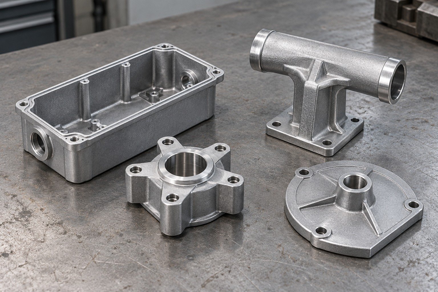
Your customer specified zinc alloy casting review starts with the complete material callout. For specialty zinc alloy casting, identify the alloy owner, product standard, casting route, working features and receiving evidence before approving stock or tooling.
For your Zamak 7 die casting and Zamak 7 machining review, confirm the ordered product and drawing. Zamak 7 properties and Zamak 7 composition should be read alongside the required filling, surface finish, assembly and inspection conditions.
| Element | Selected reference |
|---|---|
| Al | 3.7–4.3 |
| Cu | ≤0.10 |
| Mg | 0.005–0.020 |
| Zn | Balance |
Selected NADCA 2021 elements only; this is not the complete impurity specification, ingot specification or your lot analysis. Retain the full ordered standard and revision.
| Name | Your approval boundary |
|---|---|
| Zamak 7 / Alloy 7 | IZA also uses ZL7. No numeric EN casting code is assigned here. |
| HF / high-fluidity families | Confirm the exact supplier designation and specification; the family name is not one composition. |
| Proprietary zinc alloys | Confirm owner specification, supply authorization and agreed product route. |
| Customer material callout | Approve the complete standard, revision and any proposed substitution. |
IZA describes Zamak 7 as a lower-magnesium modification of Alloy 3, with tighter impurity control. Your Zamak 7 die casting services review should confirm the actual geometry and finish requirements rather than promise a universal wall thickness.
Common scale 0–0.07
Common scale 0–12
Selected NADCA 2021 casting references for context. These are not the composition of every specialty alloy, a lot report, a machinability score or a finished-part strength comparison. Zamak 3 magnesium has a conditional lower allowance in the source; retain the complete specification.
NADCA casting references ↗ IZA alloy families ↗ IZA product specifications ↗
Define the assembly inputs before repeating quantities.
Specify the alloy name, standard or owner specification, revision, product form and material records. A broad family name is not purchasing acceptance.
Define shaft, housing and working surface.
Agree stock, support and lubrication access.
Inspect the defined final state.
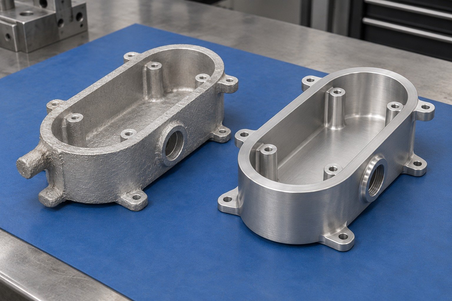
Define bore, locating land, mating material, lubrication where needed and free or installed acceptance.
Define shaft, housing and working surface.
Agree stock, support and lubrication access.
Inspect the defined final state.

Confirm the casting process, supply form and final state for the specified alloy. A prototype made by another route does not automatically reproduce production properties.
Define shaft, housing and working surface.
Agree stock, support and lubrication access.
Inspect the defined final state.

Show access to bosses, perimeter holes and internal faces. Identify usable stock and the edges that must remain intact after machining.
Define shaft, housing and working surface.
Agree stock, support and lubrication access.
Inspect the defined final state.

Define visible faces, masks, coating system and sample acceptance for the actual alloy. Do not transfer one grade’s finish route without review.
Define shaft, housing and working surface.
Agree stock, support and lubrication access.
Inspect the defined final state.
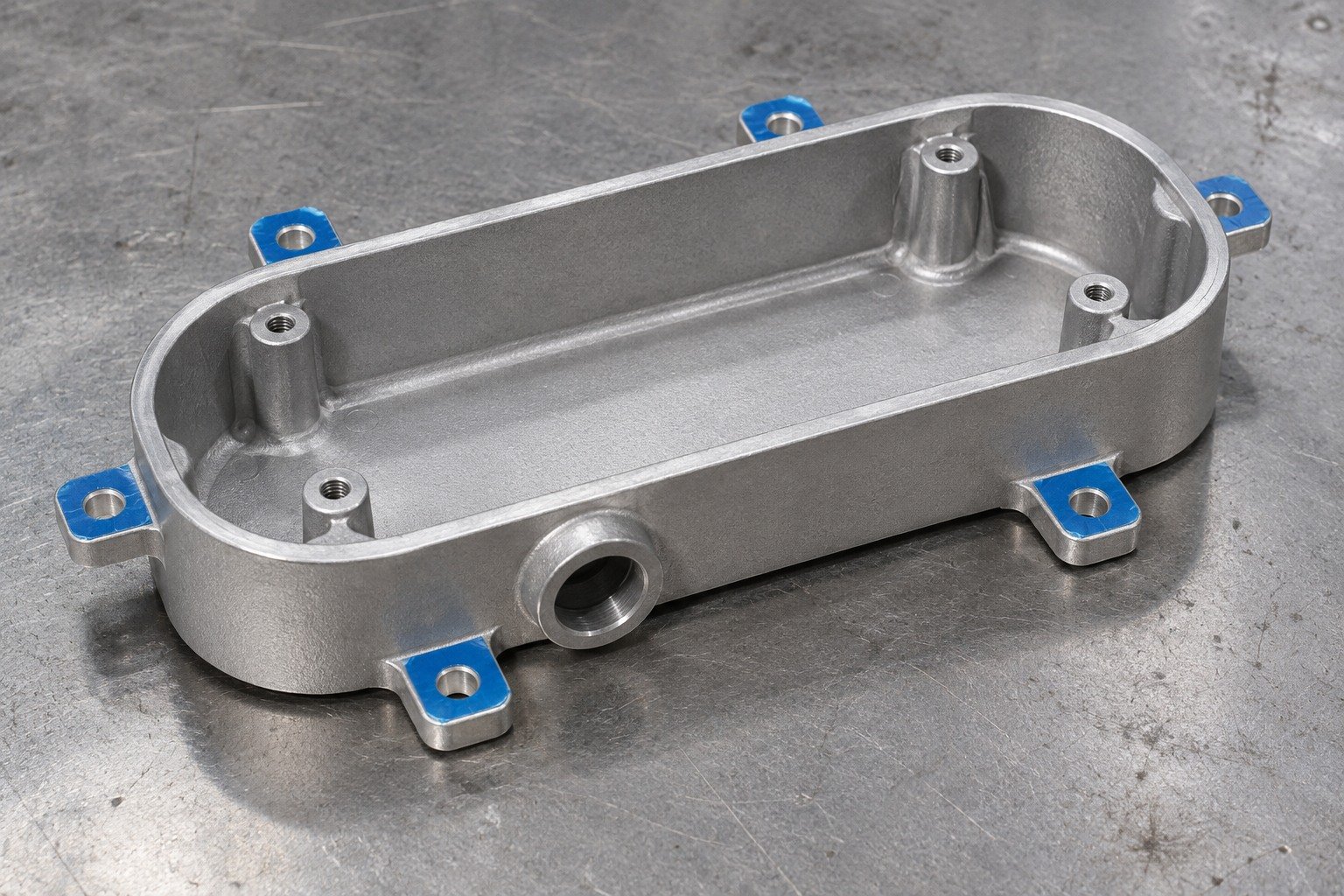
Agree lot identity, controlled dimensions, final finish, sampling and any separate functional test before release.
Define shaft, housing and working surface.
Agree stock, support and lubrication access.
Inspect the defined final state.
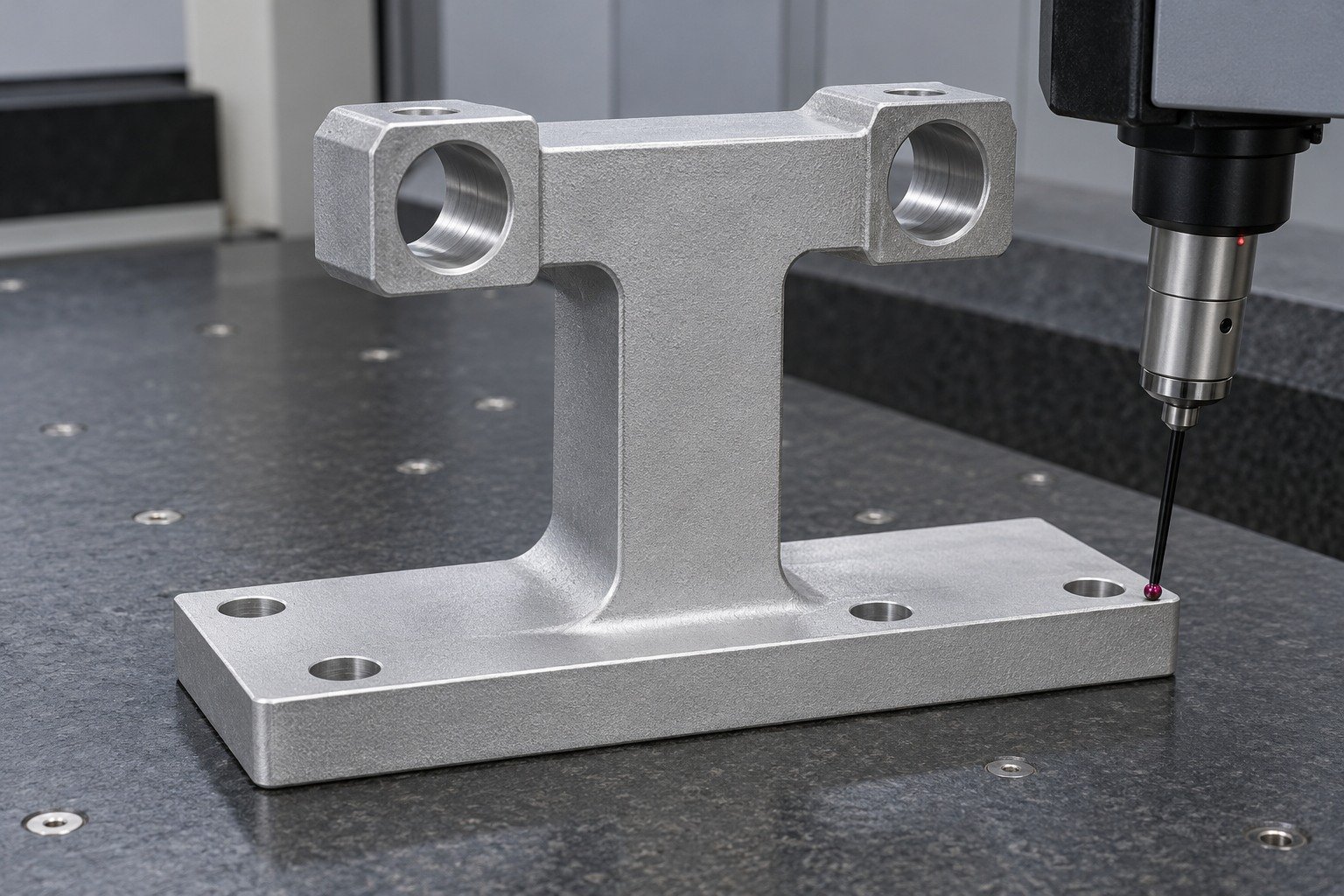
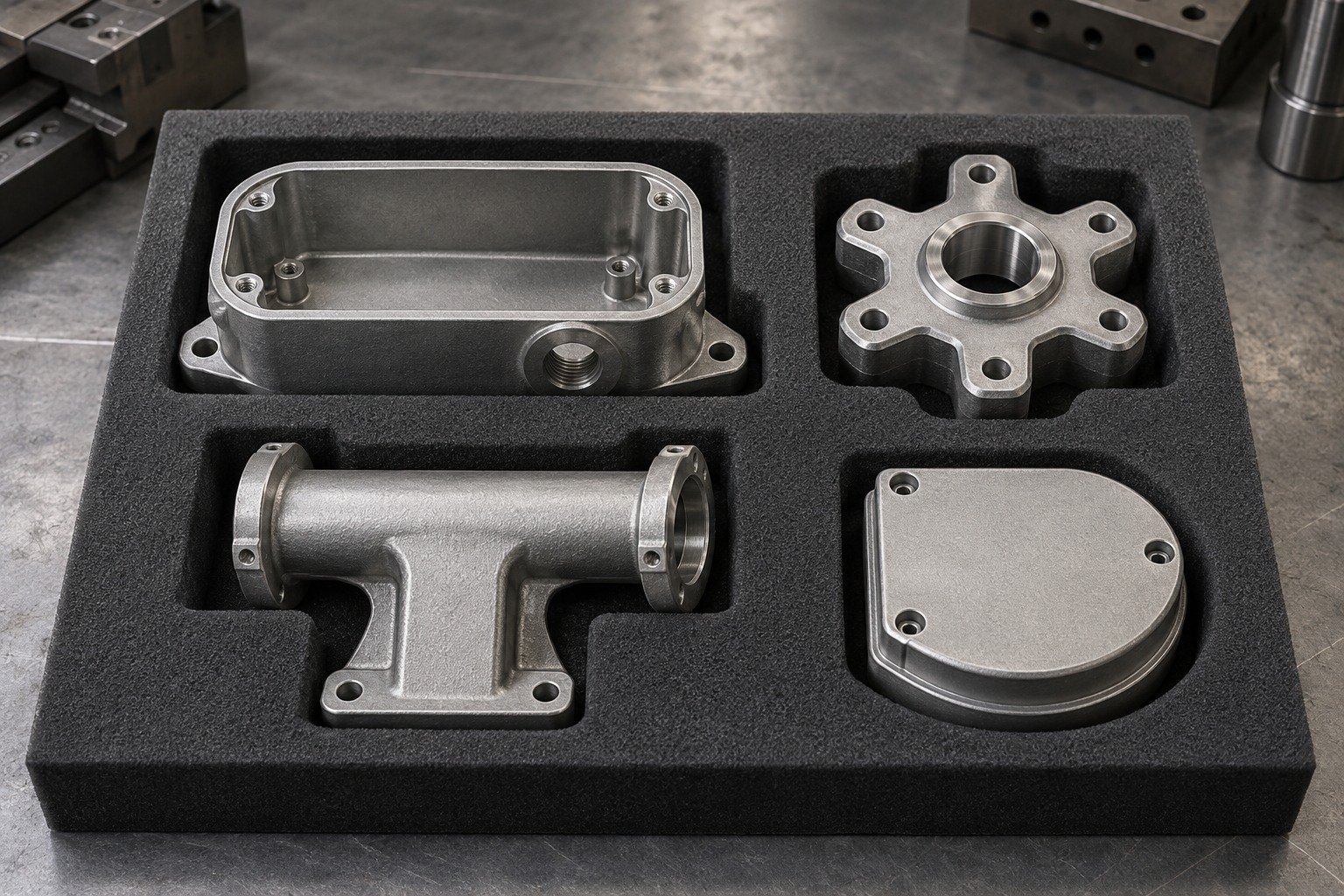
Your drawing should connect the material callout to the actual enclosure, locating hub, support or service cap. Availability and the manufacturing route are confirmed for your project.
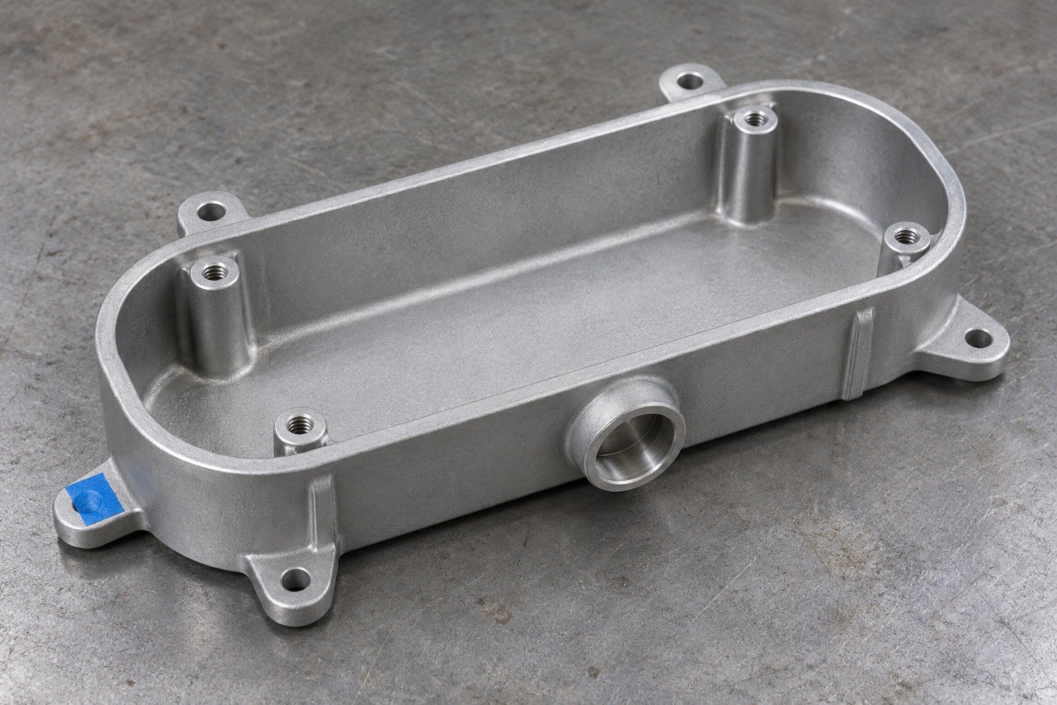
For your oblong enclosure, define the wall layout, boss access, port and mounting tabs. Review the proposed alloy against the intended filling, machining and finishing route. Review specified zinc-alloy junction enclosures against the controlled assembly.
| Your fit | What to define |
|---|---|
| Working interface | Oblong cavity, four screw bosses, port and six mounting tabs. |
| Your route | Casting product, usable stock and supported machining. |
| Your approval | Free or installed measurement state, finish and receiving records. |
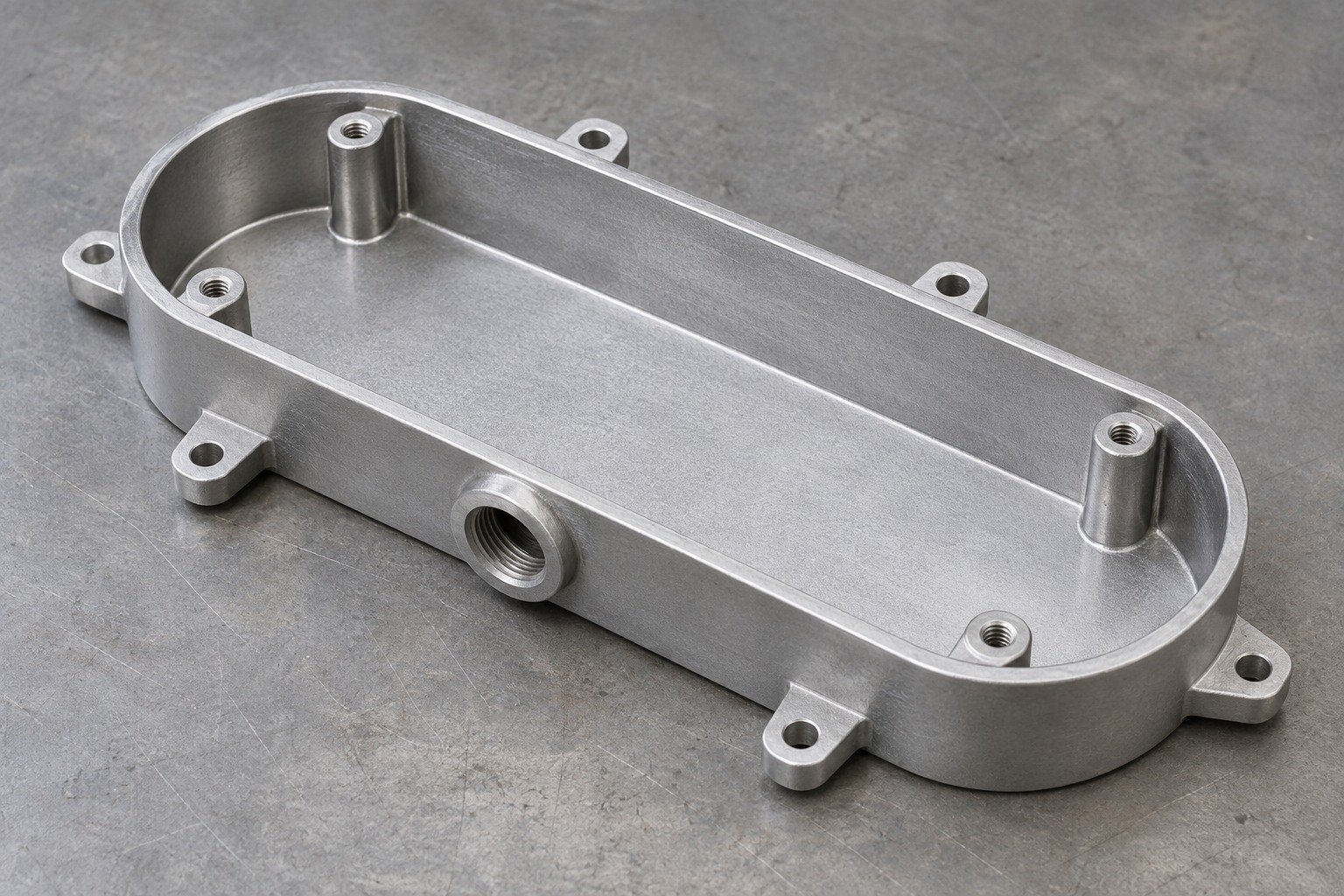
For your specified zinc-alloy machining review, connect usable stock, rigid support and cutter access to the working interface. Approve the exact alloy and final condition before applying another grade’s cutting or assembly plan.
| Your fit | What to define |
|---|---|
| Working interface | Oblong cavity, four screw bosses, port and six mounting tabs. |
| Your route | Casting product, usable stock and supported machining. |
| Your approval | Free or installed measurement state, finish and receiving records. |
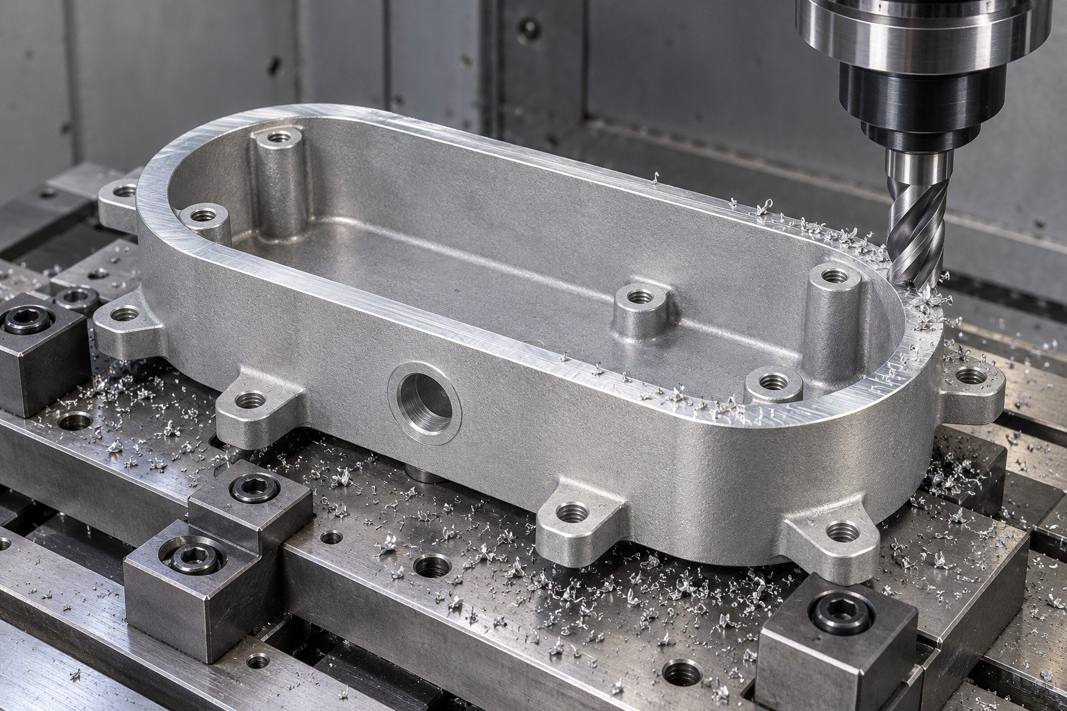
Specify the casting route, supplied state, usable allowance and secondary assembly operations and final-fit requirements. Inspect after the agreed complete route and final finish.
| Your fit | What to define |
|---|---|
| Working interface | Oblong cavity, four screw bosses, port and six mounting tabs. |
| Your route | Casting product, usable stock and supported machining. |
| Your approval | Free or installed measurement state, finish and receiving records. |
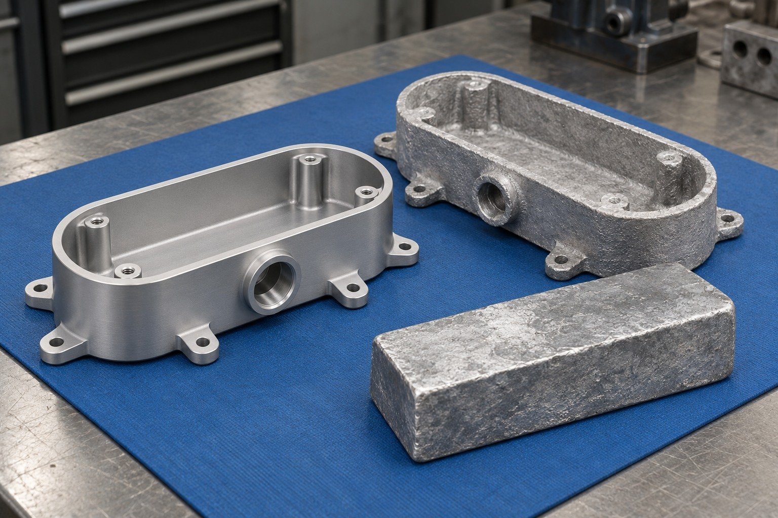
For your specified zinc-alloy machined parts, identify the material records, final dimensions, accepted edges, cleanliness and individual protection.
| Your fit | What to define |
|---|---|
| Working interface | Oblong cavity, four screw bosses, port and six mounting tabs. |
| Your route | Casting product, usable stock and supported machining. |
| Your approval | Free or installed measurement state, finish and receiving records. |
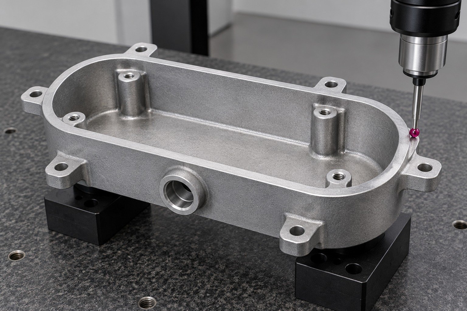
For your six-lobe hub, define the bore, locating land and lobe faces against the mating shaft and accepted clearance. Review specified zinc-alloy locating hubs against the controlled assembly.
| Your fit | What to define |
|---|---|
| Working interface | Bore, six mounting lobes and stepped locating land. |
| Your route | Casting product, usable stock and supported machining. |
| Your approval | Free or installed measurement state, finish and receiving records. |
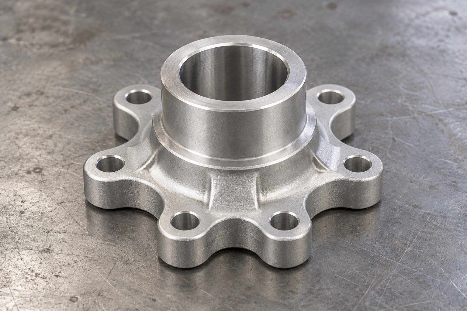
For your specified zinc-alloy machining review, connect usable stock, rigid support and cutter access to the working interface. Approve the exact alloy and final condition before applying another grade’s cutting or assembly plan.
| Your fit | What to define |
|---|---|
| Working interface | Bore, six mounting lobes and stepped locating land. |
| Your route | Casting product, usable stock and supported machining. |
| Your approval | Free or installed measurement state, finish and receiving records. |

Specify the casting route, supplied state, usable allowance and secondary assembly operations and final-fit requirements. Inspect after the agreed complete route and final finish.
| Your fit | What to define |
|---|---|
| Working interface | Bore, six mounting lobes and stepped locating land. |
| Your route | Casting product, usable stock and supported machining. |
| Your approval | Free or installed measurement state, finish and receiving records. |
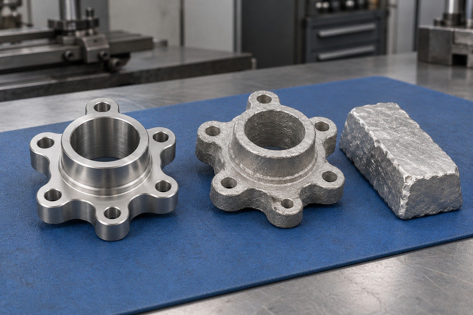
For your specified zinc-alloy machined parts, identify the material records, final dimensions, accepted edges, cleanliness and individual protection.
| Your fit | What to define |
|---|---|
| Working interface | Bore, six mounting lobes and stepped locating land. |
| Your route | Casting product, usable stock and supported machining. |
| Your approval | Free or installed measurement state, finish and receiving records. |
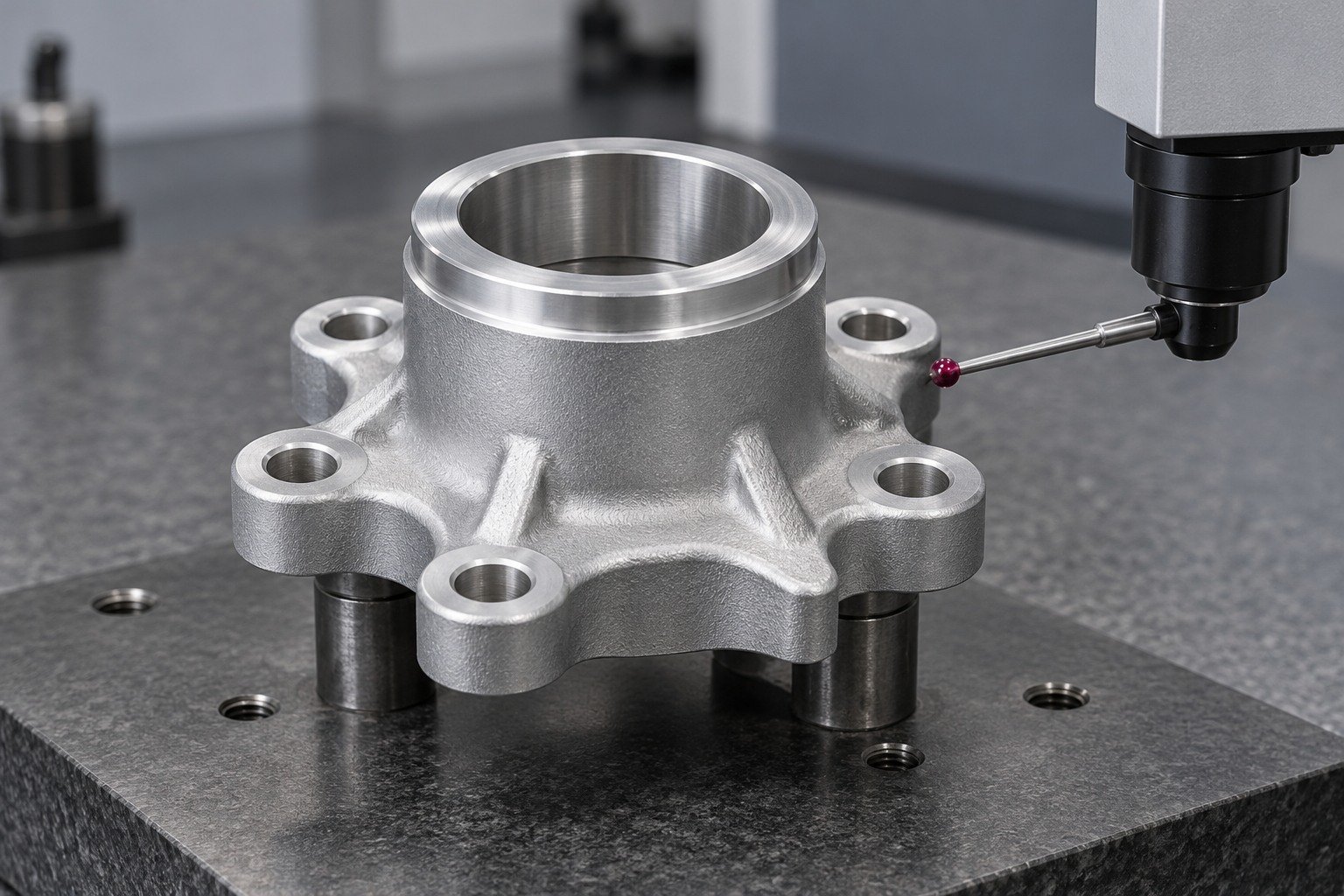
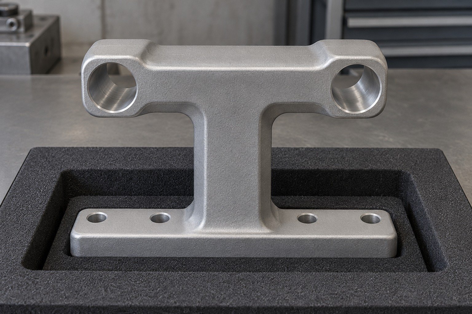
For your T-shaped support, connect the two crossbar bores to the mounting base, mating hardware and service load. Review specified zinc-alloy instrument supports against the controlled assembly.
| Your fit | What to define |
|---|---|
| Working interface | Four-hole base, upright post and two crossbar bores. |
| Your route | Casting product, usable stock and supported machining. |
| Your approval | Free or installed measurement state, finish and receiving records. |
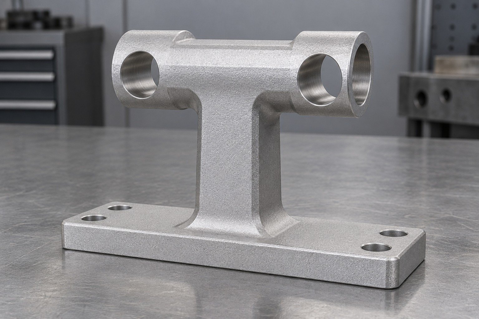
For your specified zinc-alloy machining review, connect usable stock, rigid support and cutter access to the working interface. Approve the exact alloy and final condition before applying another grade’s cutting or assembly plan.
| Your fit | What to define |
|---|---|
| Working interface | Four-hole base, upright post and two crossbar bores. |
| Your route | Casting product, usable stock and supported machining. |
| Your approval | Free or installed measurement state, finish and receiving records. |

Specify the casting route, supplied state, usable allowance and secondary assembly operations and final-fit requirements. Inspect after the agreed complete route and final finish.
| Your fit | What to define |
|---|---|
| Working interface | Four-hole base, upright post and two crossbar bores. |
| Your route | Casting product, usable stock and supported machining. |
| Your approval | Free or installed measurement state, finish and receiving records. |
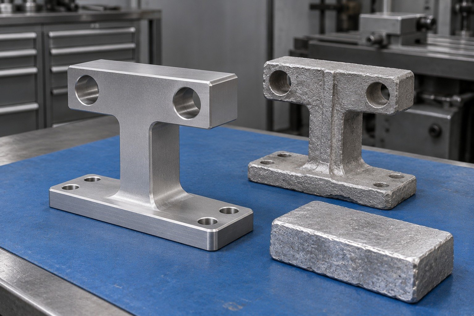
For your specified zinc-alloy machined parts, identify the material records, final dimensions, accepted edges, cleanliness and individual protection.
| Your fit | What to define |
|---|---|
| Working interface | Four-hole base, upright post and two crossbar bores. |
| Your route | Casting product, usable stock and supported machining. |
| Your approval | Free or installed measurement state, finish and receiving records. |
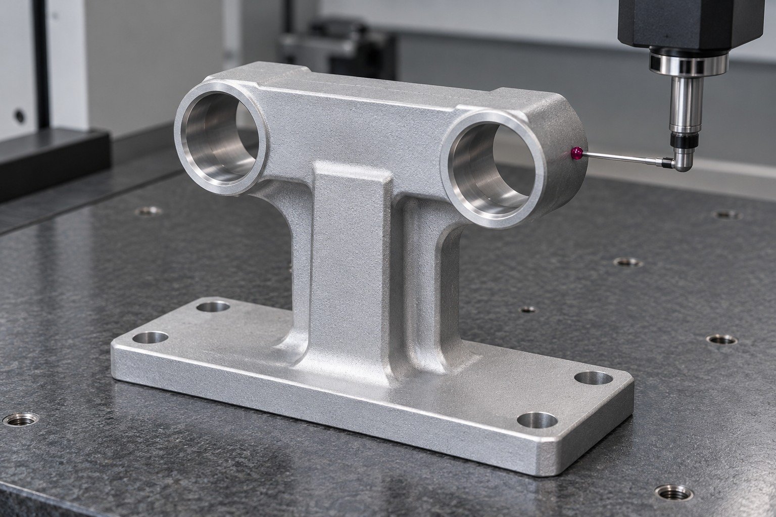
For your D-shaped cap, define the boss face, flat mating land and perimeter-hole pattern. Show any later opening or drilling operation on the controlled drawing. Review specified zinc-alloy service caps against the controlled assembly.
| Your fit | What to define |
|---|---|
| Working interface | D-shaped land, service boss and six-hole mounting pattern. |
| Your route | Casting product, usable stock and supported machining. |
| Your approval | Free or installed measurement state, finish and receiving records. |

For your specified zinc-alloy machining review, connect usable stock, rigid support and cutter access to the working interface. Approve the exact alloy and final condition before applying another grade’s cutting or assembly plan.
| Your fit | What to define |
|---|---|
| Working interface | D-shaped land, service boss and six-hole mounting pattern. |
| Your route | Casting product, usable stock and supported machining. |
| Your approval | Free or installed measurement state, finish and receiving records. |

Specify the casting route, supplied state, usable allowance and secondary assembly operations and final-fit requirements. Inspect after the agreed complete route and final finish.
| Your fit | What to define |
|---|---|
| Working interface | D-shaped land, service boss and six-hole mounting pattern. |
| Your route | Casting product, usable stock and supported machining. |
| Your approval | Free or installed measurement state, finish and receiving records. |

For your specified zinc-alloy machined parts, identify the material records, final dimensions, accepted edges, cleanliness and individual protection.
| Your fit | What to define |
|---|---|
| Working interface | D-shaped land, service boss and six-hole mounting pattern. |
| Your route | Casting product, usable stock and supported machining. |
| Your approval | Free or installed measurement state, finish and receiving records. |

For your Specialty Zinc Alloy machining allowance review, identify where cast stock must clean up and how each critical feature is supported.

Define the hub bore, locating land and six lobe faces in the supported route.
Review the Process →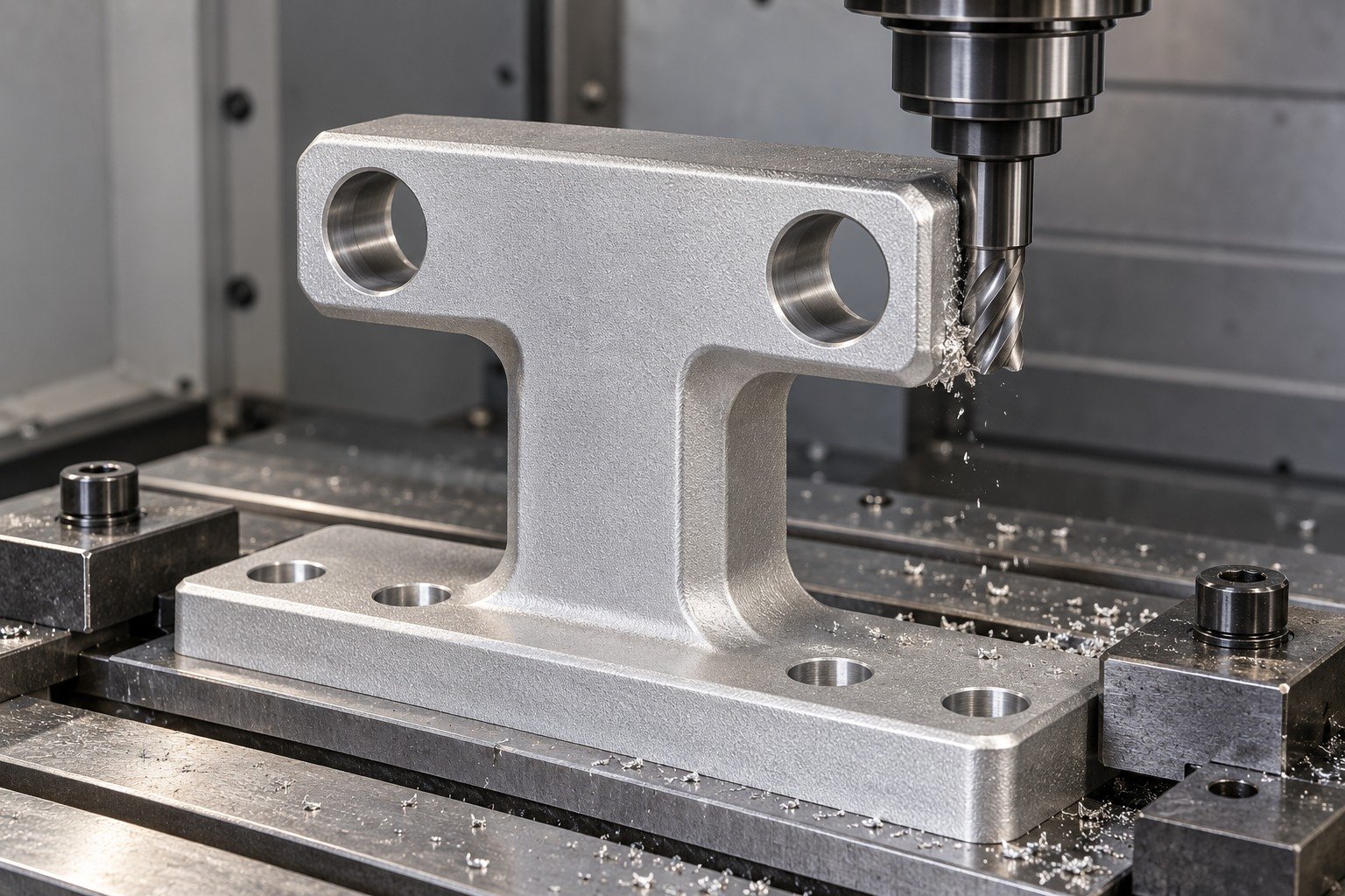
Support the upright post and crossbar while machining the broad base datum.
Review the Process →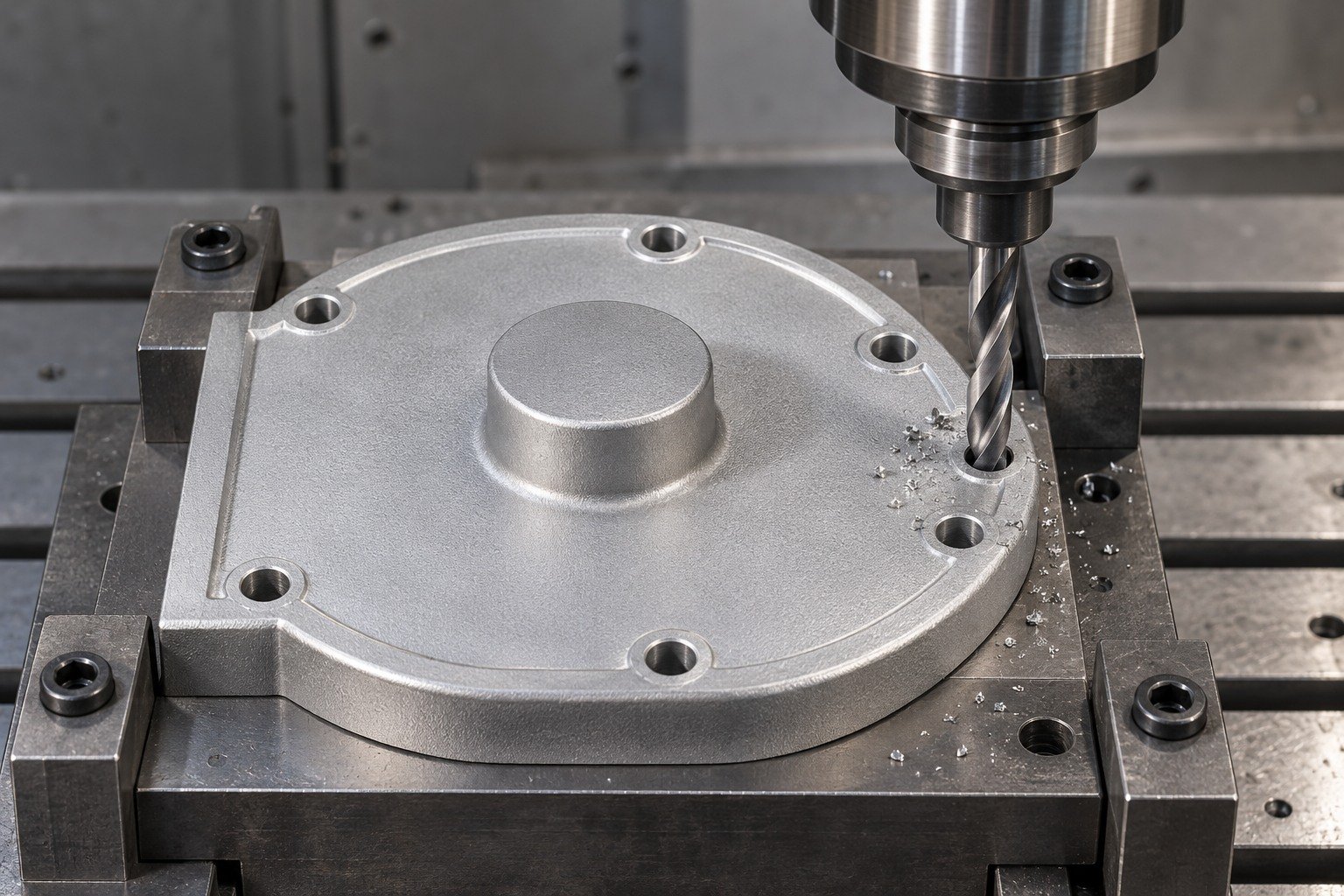
Define backed perimeter drilling and access around the service-cap boss.
Review the Process →
Review the oblong enclosure side port and mating flange after casting.
Review the Process →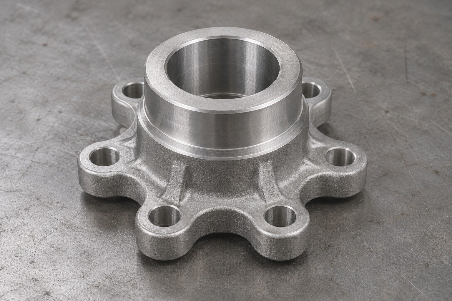

Agree visible marks, finish preparation, coating acceptance and protected delivery. Check dimensions in the final surface state.
Surface Finishing →| Your decision | What to confirm |
|---|---|
| Die casting or gravity route | Agree stock, geometry, tooling and inspection separately. |
| Prototype and production | Do not carry one route’s properties into another without review. |
| Bearing interface | Define load, speed, lubrication, mating material and final clearance. |
| Material change | Obtain drawing-authority approval and receiving criteria. |
A specialty-alloy name does not establish finished-part capacity or supply availability. Agree the exact material, filling route, usable machining allowance and final fit. Review substitution with the drawing authority before purchase.
Compare Zinc Alloys →Product identity and ordered requirements.
Complete route and locating relationship.
Final working surfaces and evidence.
Identify the exact alloy, ordered standard or owner specification, revision, casting route, supply state, lot identity and records.

Approve flange, bore, foot and port relationships after the complete route. A first casting sample and a first finished-route sample answer different questions.

Verify the final hub bore, lobe faces, cap land or instrument base in the measurement state specified on your drawing.
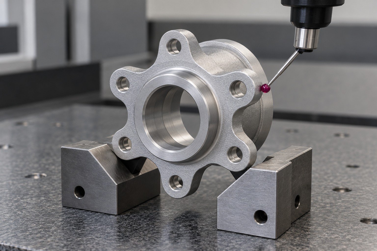
Agree protection, cleanliness, lot identity and receiving documents for the actual mating surfaces.

Connect China manufacturing with Dallas-area coordination for drawing review, sample decisions and delivery requirements.
Compare the same alloy specification, drawing revision, route, usable stock and final acceptance. Separate tooling and repeat-piece cost on that basis.
Send the complete material callout, controlled drawing, product form, proposed casting route and quantities. Availability, process fit, tooling and required records are reviewed for your quotation; not every proprietary grade or route is automatically available.
Retain the full alloy and product specification, revision and impurity requirements. Zamak 7 / Alloy 7 and the IZA ZL7 name are references; no numeric EN casting code is assigned here.
Review locating support, allowance, bore and thread access, accepted burrs and final coating with the actual casting. Material identity does not remove the need to approve the finished fit.
Only after reviewing the complete supplier specification, geometry, mechanical requirements, finish and receiving criteria with the drawing authority. A family description is not substitution approval.
Provide the full designation, standard, revision and required product form. Confirm cast-part versus ingot/liquid references and approve the actual ordered chemistry and records.
Use the same controlled drawing, exact material, casting route, quantities, finish, critical fits and inspection scope. Include tooling ownership and expected repeat demand.
No. The selected Zamak 7 table is a reference for that grade. Proprietary and customer-defined alloys need their own full specification and material-lot evidence.
Identify the mating parts, service environment, loads and duration, final coating and measurement state. Agree dimensional, appearance and any separate integrity or duty tests.





