

Injection Molding
Tooling and molding for your repeat plastic parts.
From prototype to production, coordinated manufacturing solutions for your custom parts.
View All Services →
Precision parts for your tight tolerances and complex geometry.
Tooling and molding for your repeat plastic parts.

Metal casting options for your part and production volume.

Cutting, forming and welding for your fabricated parts.

Custom profiles for your section, length and finish requirements.

Finishes for your appearance, corrosion and wear requirements.

Sub-assemblies and final builds for your production program.

Production tooling built around your process and volume.

Prototype parts to check fit, function and design.
DFM, process planning and production support for your project.
Inspection, documentation, inventory and delivery planning for your program.
Choose air- or liquid-cooling components around your thermal and mechanical requirements.

Manufacturing support for your cold plates, manifolds and cooling assemblies.

Find components for your power electronics, energy, laser and telecom application.

Components for your electronic systems.
Start with your functional and quality requirements.
Build around your operating environment.
From prototype to production, review material performance, manufacturability and cost for your part.
Review grade, temper and finish for your metal parts.
 AluminumStrength, weight and machining›
 Stainless SteelCorrosion and finish requirements›
 Carbon & Alloy SteelDiscuss grade and heat treatment›
 Tool SteelDiscuss tooling and wear needs›
 TitaniumReview grade and part geometry›
 Copper & Brass & BronzeDiscuss conductivity and machining›
Match your polymer to function, process and environment.
 ABSReview enclosure and molding needs›
 Polycarbonate (PC)Discuss clarity and impact needs›
 Nylon (PA)Review moisture and wear conditions›
 POM / AcetalReview fit and sliding features›
 PEEKDiscuss operating conditions›
 PTFEReview friction and chemical exposure›
 ULTEM / PEIDiscuss thermal and electrical needs›
Confirm grade availability and application requirements.
 Silicone / LSRDiscuss flexible component needs›
 TPU / TPEReview flexibility and processing›
 EPDMReview weathering and chemical exposure.›
 NBRReview oil and fuel exposure.›
 FKMReview temperature and chemical exposure.›
 G10 / FR4Review insulation and laminate needs›
 CompositesReview stiffness, weight and laminate.›Customer-Specified MaterialsConfirm your grade and requirements.›Other Specialty MaterialsDiscuss your application and grade.›
Practical guidance for your part geometry and material decisions.
Prepare your process, budget and sourcing questions.
Build your knowledge before production.
Learn who we are and how we operate.
Find our U.S. support team or start a conversation.

For your C93200 machining project, define the shaft, housing and lubrication path before the first cut. Review SAE 660 bronze machining around your final bore, thrust face and receiving evidence.
For your C93200 CNC machining review, connect the controlled drawing to the shaft, housing, sliding face and replenishment access. C93200 bronze bushings and C93200 bronze bearings need an agreed final measurement state.
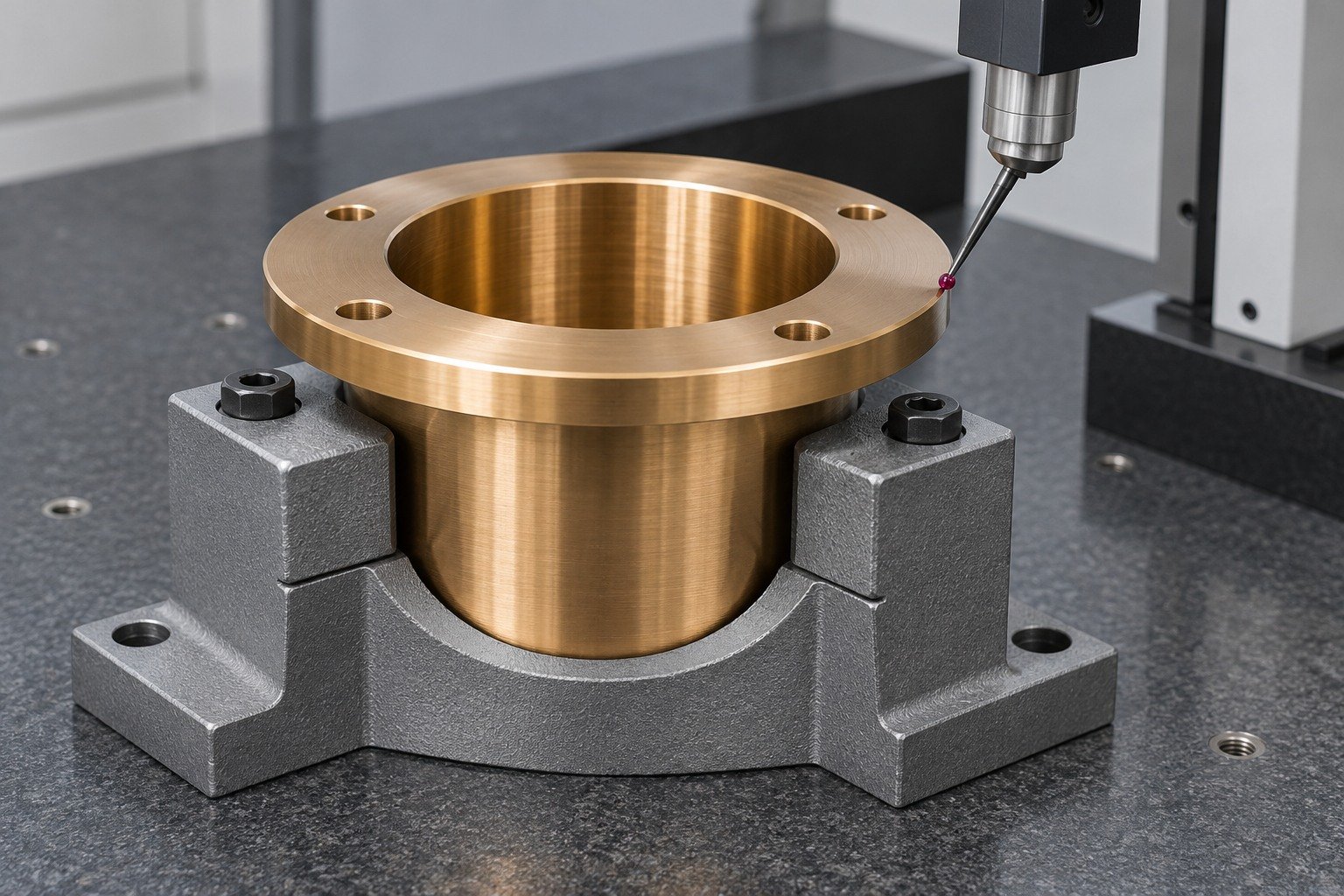
For your custom SAE 660 bushings, identify the flange datum, housing restraint, shaft and radial oil-port position. Review custom C93200 bushings against the controlled assembly.
| Your fit | What to define |
|---|---|
| Working interface | Free bore, installed bore, flange face and housing relationship. |
| Your route | Casting product, usable stock and supported machining. |
| Your approval | Final measurement state, surface and receiving evidence. |
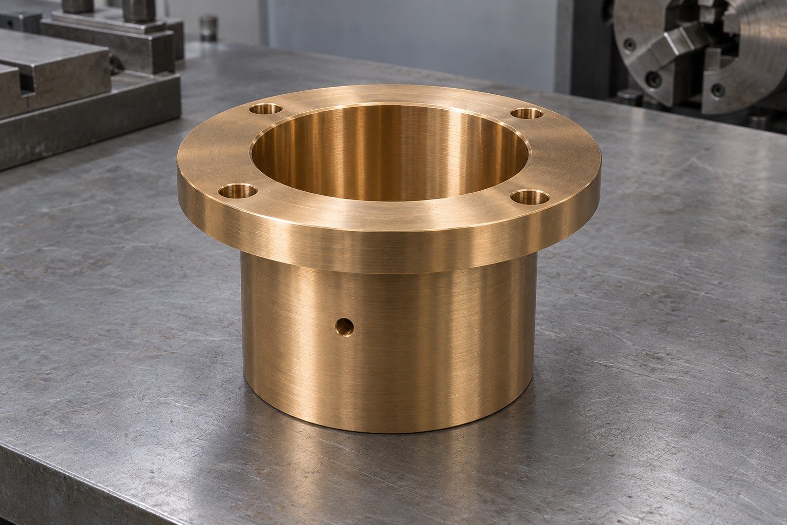
Your C93200 machining services review should identify locating support, accessible oil ports and the surfaces inspected after the final operation.
| Your fit | What to define |
|---|---|
| Working interface | Free bore, installed bore, flange face and housing relationship. |
| Your route | Casting product, usable stock and supported machining. |
| Your approval | Final measurement state, surface and receiving evidence. |
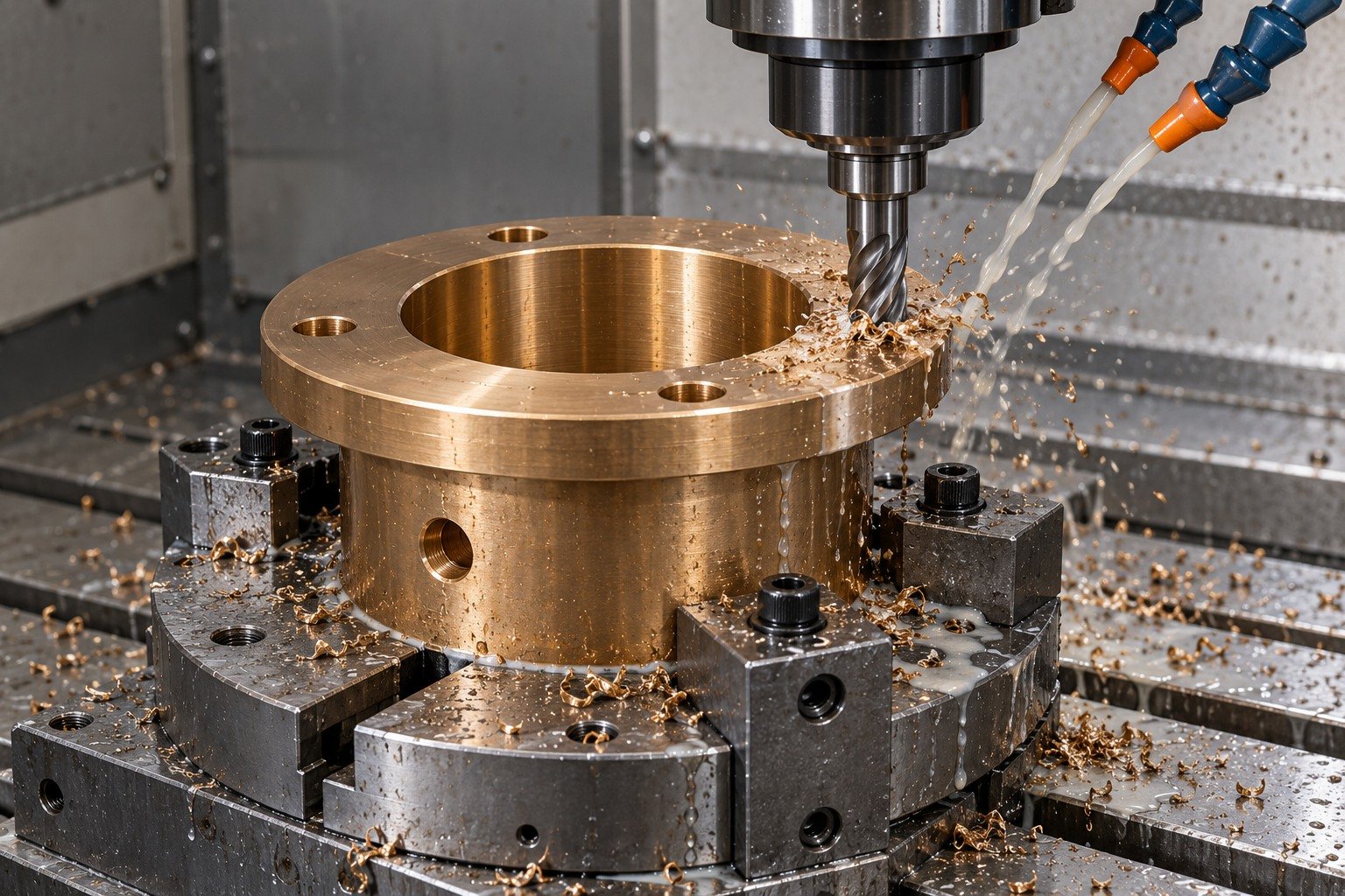
Specify the actual casting route and machining allowance. Agree whether final inspection uses a free component or a defined representative housing.
| Your fit | What to define |
|---|---|
| Working interface | Free bore, installed bore, flange face and housing relationship. |
| Your route | Casting product, usable stock and supported machining. |
| Your approval | Final measurement state, surface and receiving evidence. |
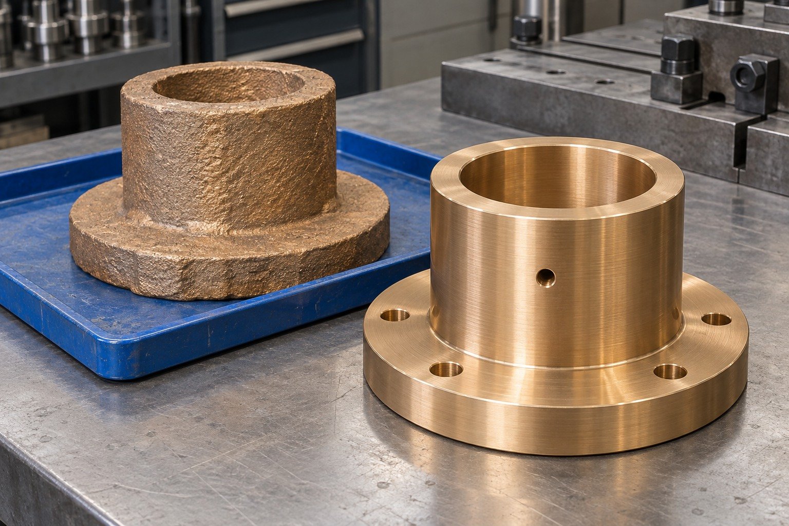
For your C93200 machined parts, identify required material records, final dimensions, accepted edges, cleanliness and individual protection.
| Your fit | What to define |
|---|---|
| Working interface | Free bore, installed bore, flange face and housing relationship. |
| Your route | Casting product, usable stock and supported machining. |
| Your approval | Final measurement state, surface and receiving evidence. |

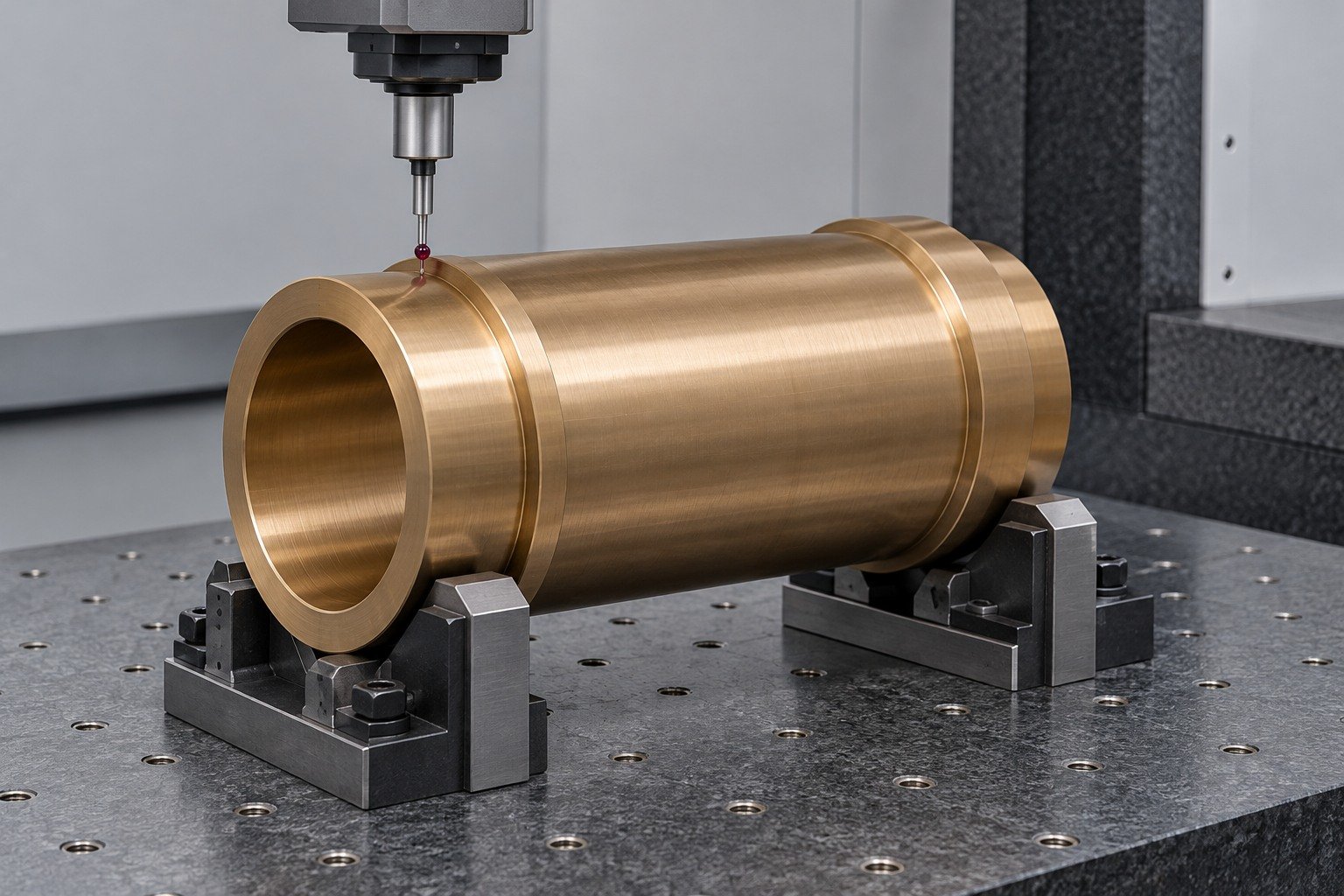
Your C93200 bronze sleeve machining review should connect supported bore length, wall thickness and final assembly state. Review C93200 bronze sleeves against the controlled assembly.
| Your fit | What to define |
|---|---|
| Working interface | Supported wall, bore, outside steps and measurement state. |
| Your route | Casting product, usable stock and supported machining. |
| Your approval | Final measurement state, surface and receiving evidence. |

Your C93200 machining services review should identify locating support, accessible oil ports and the surfaces inspected after the final operation.
| Your fit | What to define |
|---|---|
| Working interface | Supported wall, bore, outside steps and measurement state. |
| Your route | Casting product, usable stock and supported machining. |
| Your approval | Final measurement state, surface and receiving evidence. |

Specify the actual casting route and machining allowance. Agree whether final inspection uses a free component or a defined representative housing.
| Your fit | What to define |
|---|---|
| Working interface | Supported wall, bore, outside steps and measurement state. |
| Your route | Casting product, usable stock and supported machining. |
| Your approval | Final measurement state, surface and receiving evidence. |
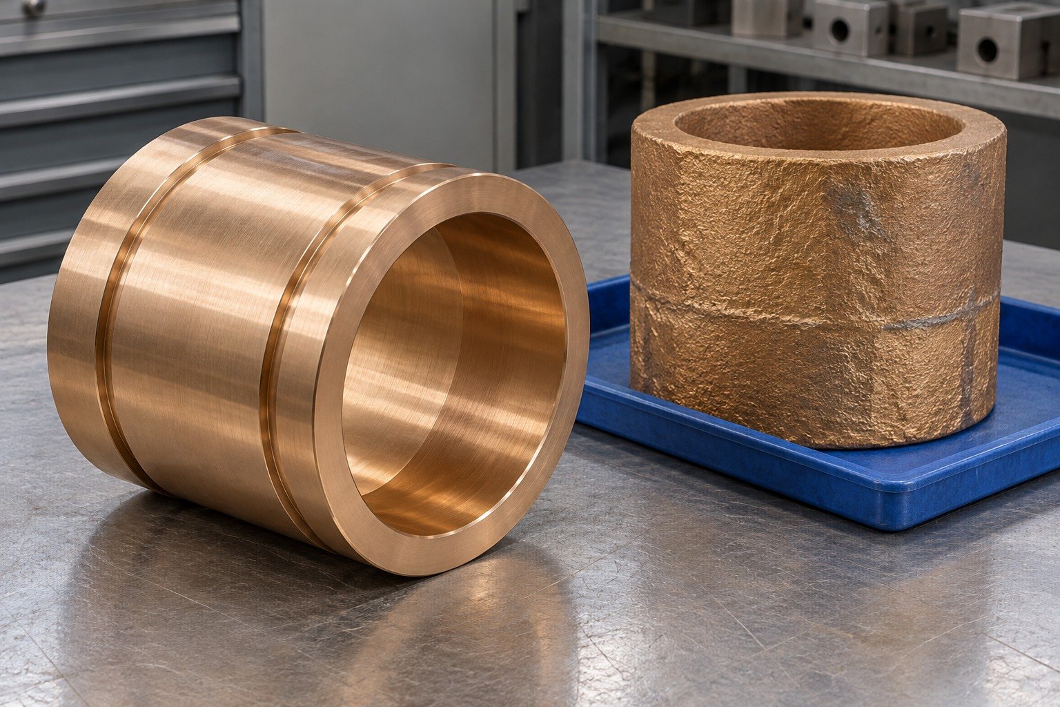
For your C93200 machined parts, identify required material records, final dimensions, accepted edges, cleanliness and individual protection.
| Your fit | What to define |
|---|---|
| Working interface | Supported wall, bore, outside steps and measurement state. |
| Your route | Casting product, usable stock and supported machining. |
| Your approval | Final measurement state, surface and receiving evidence. |
For your C93200 thrust washers, define the mating thrust faces, thickness, flatness basis and lubrication-channel exits. Review custom C93200 thrust washers against the controlled assembly.
| Your fit | What to define |
|---|---|
| Working interface | Thrust face, mating surface, thickness and channel layout. |
| Your route | Casting product, usable stock and supported machining. |
| Your approval | Final measurement state, surface and receiving evidence. |
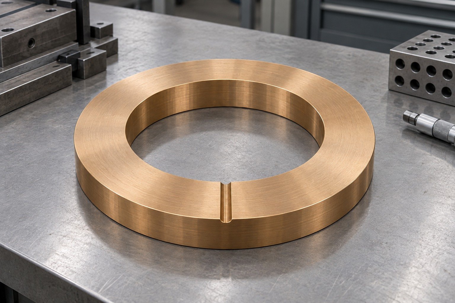
Your C93200 machining services review should identify locating support, accessible oil ports and the surfaces inspected after the final operation.
| Your fit | What to define |
|---|---|
| Working interface | Thrust face, mating surface, thickness and channel layout. |
| Your route | Casting product, usable stock and supported machining. |
| Your approval | Final measurement state, surface and receiving evidence. |
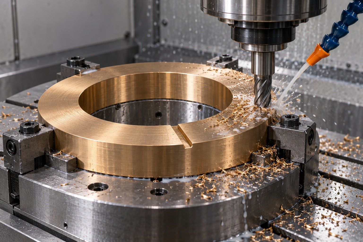
Specify the actual casting route and machining allowance. Agree whether final inspection uses a free component or a defined representative housing.
| Your fit | What to define |
|---|---|
| Working interface | Thrust face, mating surface, thickness and channel layout. |
| Your route | Casting product, usable stock and supported machining. |
| Your approval | Final measurement state, surface and receiving evidence. |
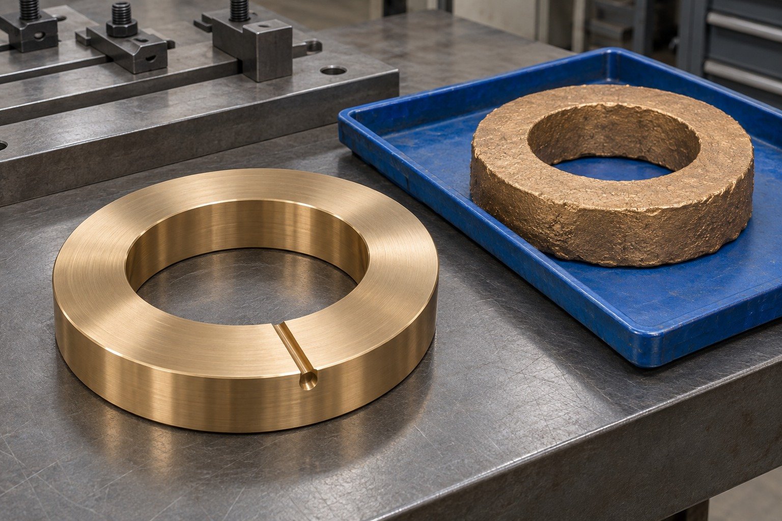
For your C93200 machined parts, identify required material records, final dimensions, accepted edges, cleanliness and individual protection.
| Your fit | What to define |
|---|---|
| Working interface | Thrust face, mating surface, thickness and channel layout. |
| Your route | Casting product, usable stock and supported machining. |
| Your approval | Final measurement state, surface and receiving evidence. |
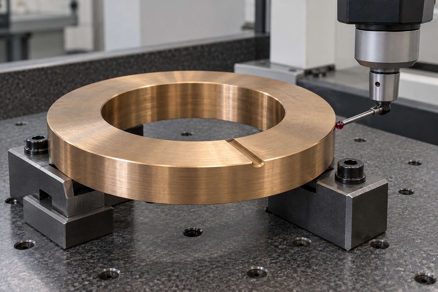
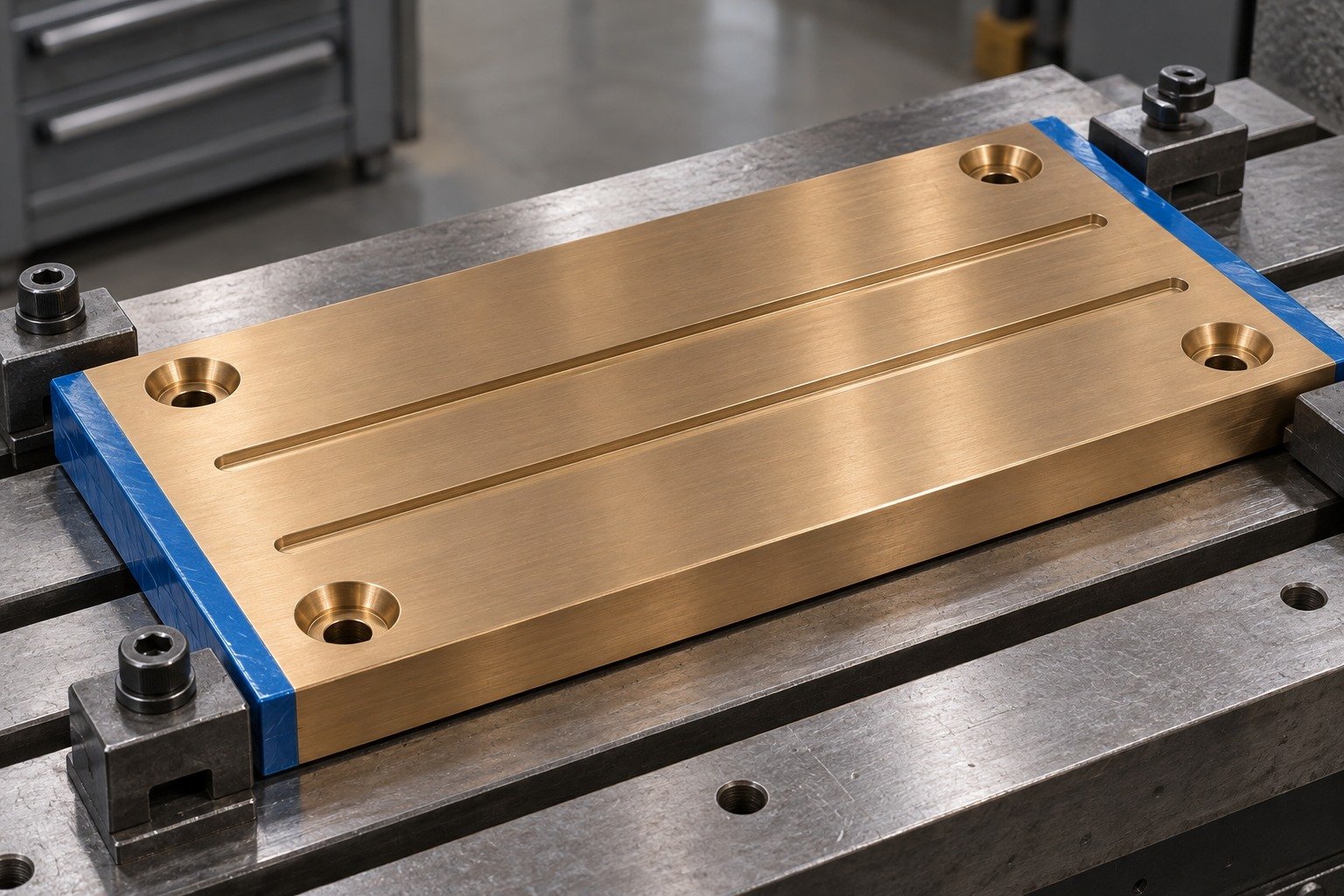
For your C93200 wear plates, connect the broad sliding face, mounting holes and approved lubrication channels to the backing structure. Review C93200 wear plates against the controlled assembly.
| Your fit | What to define |
|---|---|
| Working interface | Working face, mounting recesses and supporting structure. |
| Your route | Casting product, usable stock and supported machining. |
| Your approval | Final measurement state, surface and receiving evidence. |
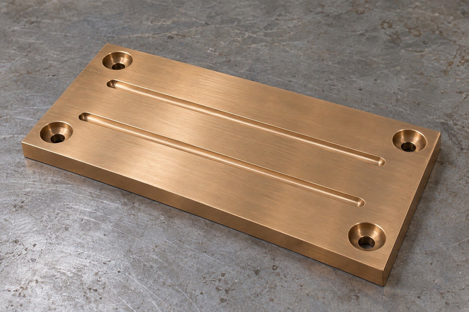
Your C93200 machining services review should identify locating support, accessible oil ports and the surfaces inspected after the final operation.
| Your fit | What to define |
|---|---|
| Working interface | Working face, mounting recesses and supporting structure. |
| Your route | Casting product, usable stock and supported machining. |
| Your approval | Final measurement state, surface and receiving evidence. |
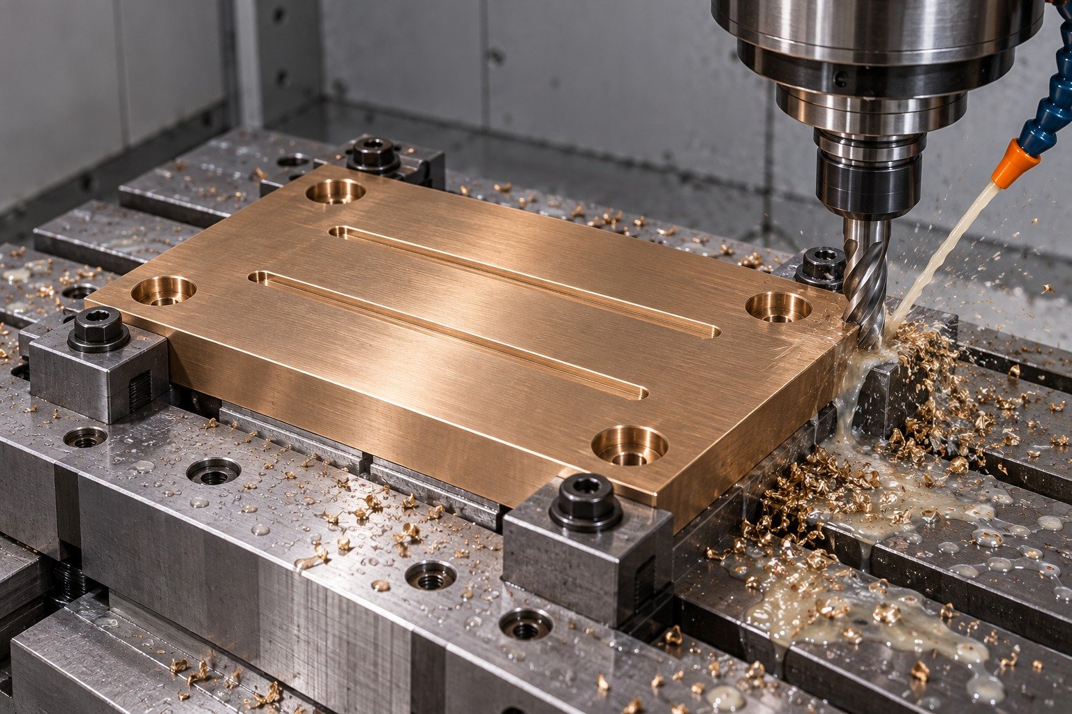
Specify the actual casting route and machining allowance. Agree whether final inspection uses a free component or a defined representative housing.
| Your fit | What to define |
|---|---|
| Working interface | Working face, mounting recesses and supporting structure. |
| Your route | Casting product, usable stock and supported machining. |
| Your approval | Final measurement state, surface and receiving evidence. |

For your C93200 machined parts, identify required material records, final dimensions, accepted edges, cleanliness and individual protection.
| Your fit | What to define |
|---|---|
| Working interface | Working face, mounting recesses and supporting structure. |
| Your route | Casting product, usable stock and supported machining. |
| Your approval | Final measurement state, surface and receiving evidence. |
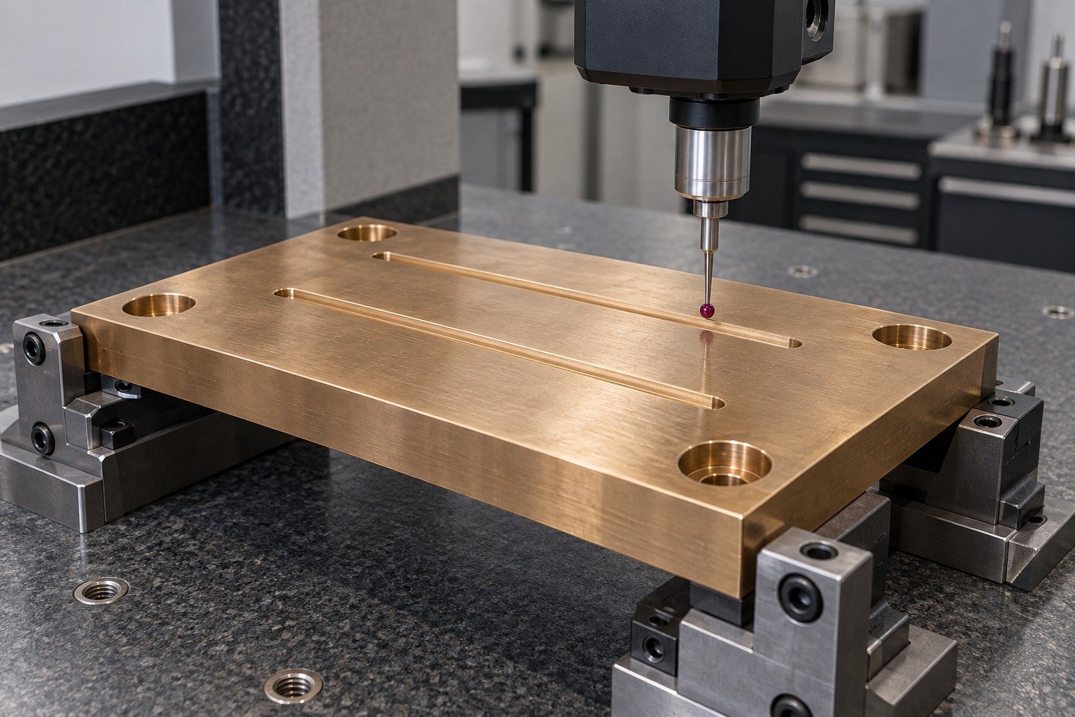
C932 bearing bronze is a leaded cast alloy. Your C93200 bronze properties review needs the actual product standard, casting route and test basis. The C93200 bronze composition below is one selected continuous-cast reference, not your material-lot analysis.
| Element | Concast continuous-cast reference · wt.% |
|---|---|
| Copper | 81.0–85.0 |
| Lead | 6.0–8.0 |
| Tin | 6.3–7.5 |
| Zinc | 2.0–4.0 |
| Iron | ≤0.20 |
| Phosphorus | ≤1.50 |
| Nickel · includes Co | ≤1.00 |
| Aluminum / Silicon | ≤0.005 each |
| Sulfur / Antimony | ≤0.08 / ≤0.35 |
Selected ASTM B505/B505M-23 continuous-cast reference. Cu minimum may be calculated as Cu + Ni; combined Cu + named elements ≥99.0% is not pure-copper content. Do not transfer the P limit to other specifications or casting routes.
| Your reference | What to confirm |
|---|---|
| C93200 / SAE 660 bronze | Common supplier association; retain the full ordered requirements. |
| CuSn7Zn4Pb7-C / CC493K | Comparable EN 1982 casting designation; chemistry is not identical. |
| RG7 / Rg7 | European trade reference; retain standard, revision and casting route. |
| C93200 ASTM B505 | Specify the ordered revision, product form and required records. |
The cited EN comparison uses Pb 5–8% and Sn 6–8%; the selected US continuous-cast data above uses different intervals. A familiar purchasing name does not approve substitution.
Common scale 0–10
Common scale 0–100
Selected Concast US continuous-cast and BEYER EN casting references. Your C93200 machinability review uses a relative cutting reference; these indices do not predict machining time, bearing life, permitted load or quote price. Review the exact product before approval.
Concast C93200 ↗ BEYER CC493K ↗ Concast C90300 ↗ Concast C95400 ↗
Review stock route, tool access and final mating geometry together.
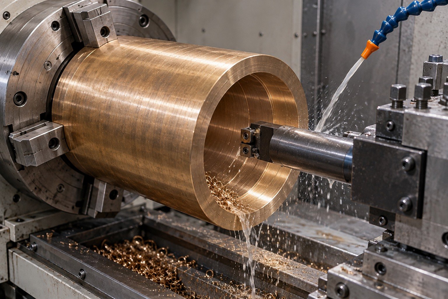
For C93200 turning and C93200 boring, review bore support, wall thickness and locating steps.
Review the Process →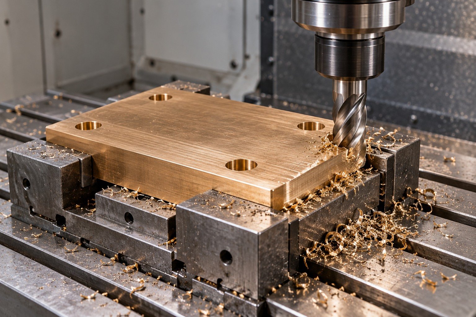
Connect your wear-plate working face and mounting recesses to one locating plan.
Review the Process →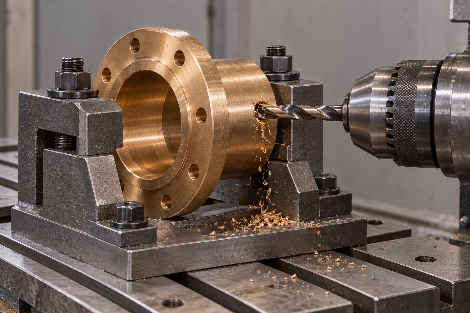
Define radial oil-port position, accessible drilling and accepted internal exits.
Review the Process →
Approve channel layout and working-face requirements before machining.
Review the Process →Define the assembly inputs before repeating quantities.
Identify the ordered casting product and usable allowance. A solid C93200 sleeve and an oil-impregnated sintered bearing need separate material and machining reviews.
Define shaft, housing and working surface.
Agree stock, support and lubrication access.
Inspect the defined final state.
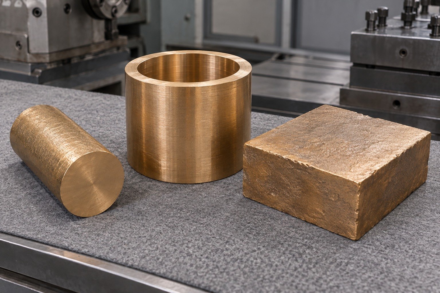
State mating sizes, wall thickness, restraint and measurement state. Do not choose a universal press-fit or running-clearance number from the alloy name.
Define shaft, housing and working surface.
Agree stock, support and lubrication access.
Inspect the defined final state.
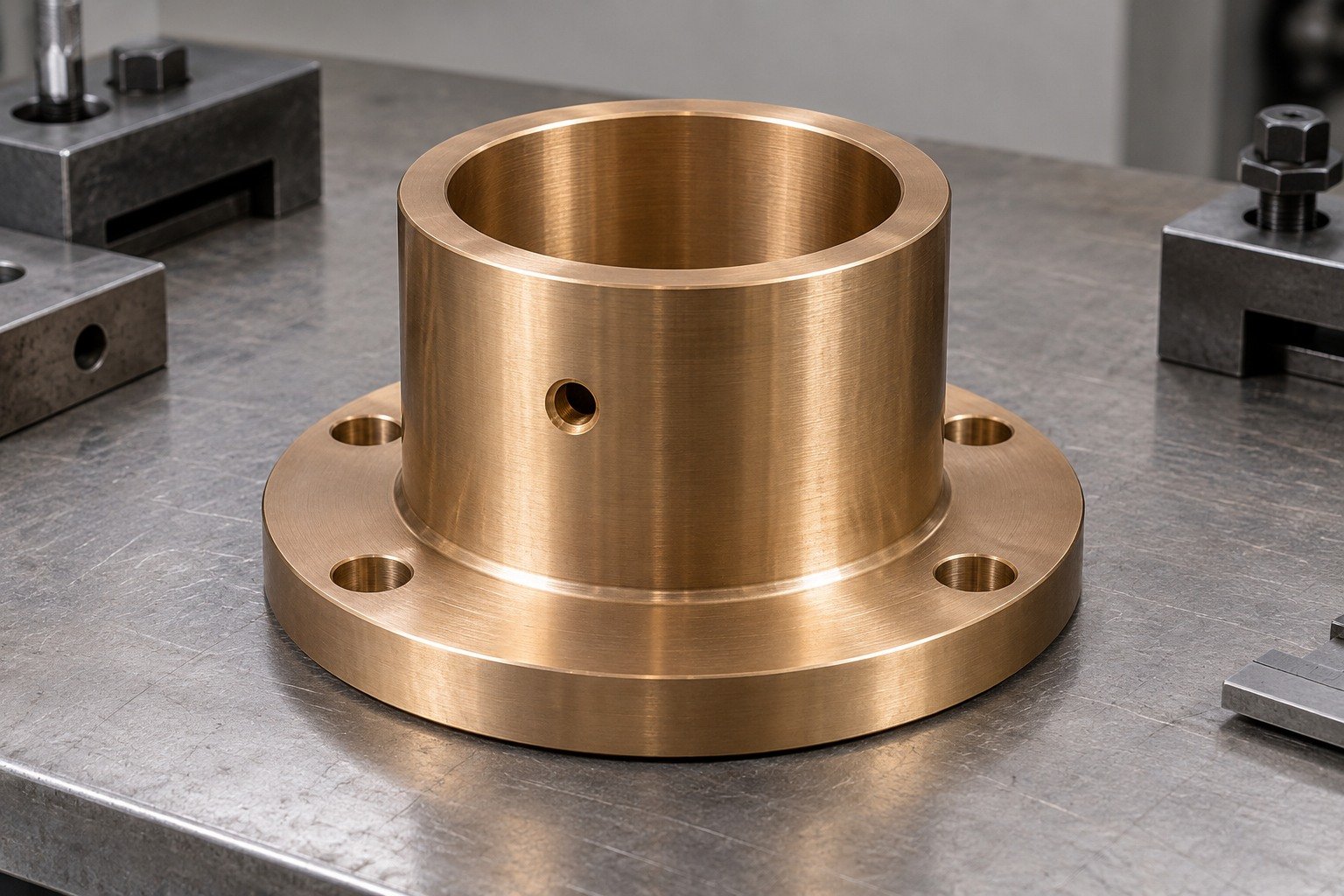
Your housing and assembly method can affect final bore acceptance. Agree the free or installed inspection condition and the actual drawing limits before repeating parts.
Define shaft, housing and working surface.
Agree stock, support and lubrication access.
Inspect the defined final state.
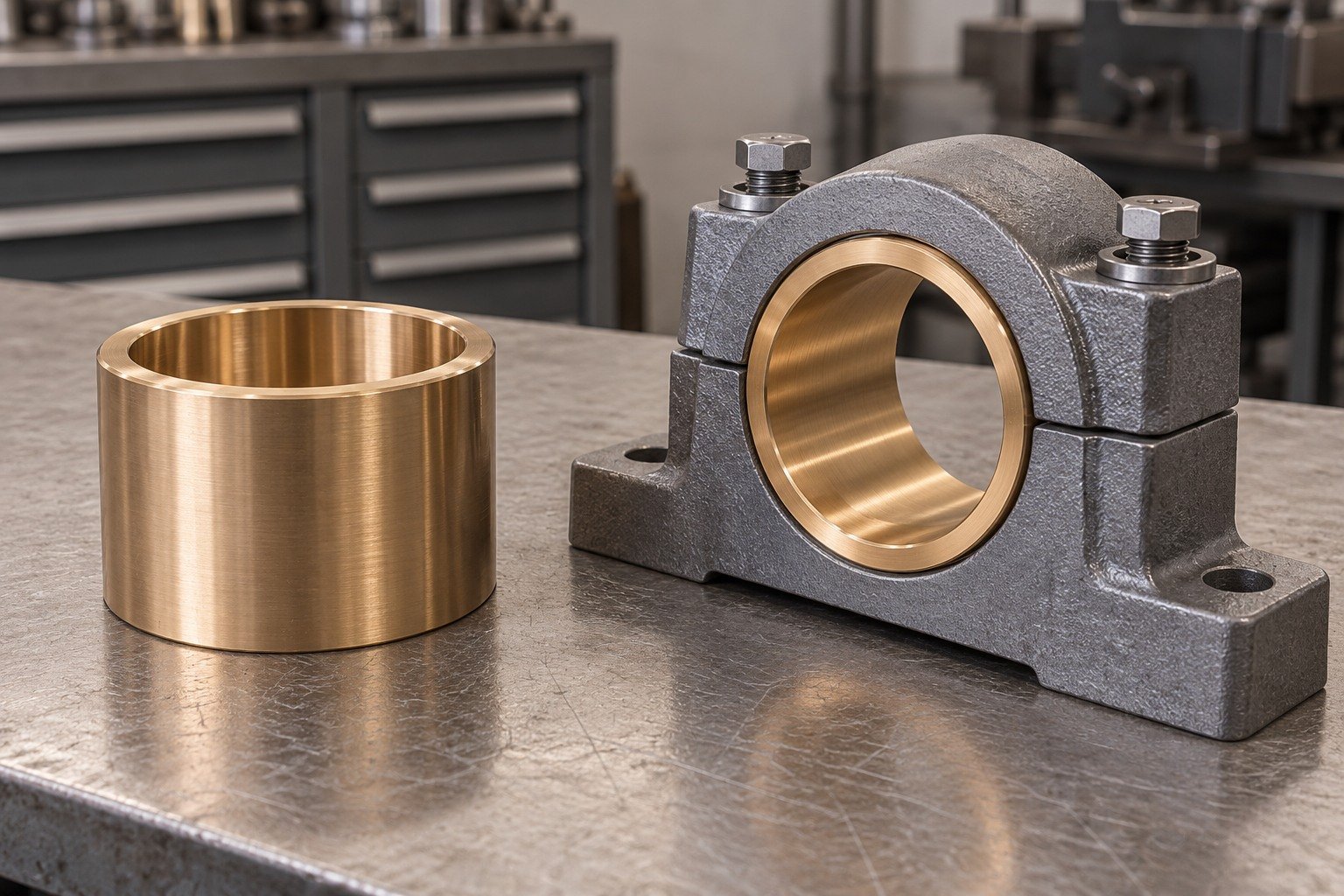
For C93200 oil groove machining, provide the approved layout, depth, exits and accepted edges. A groove alone does not establish lubrication adequacy or service life.
Define shaft, housing and working surface.
Agree stock, support and lubrication access.
Inspect the defined final state.
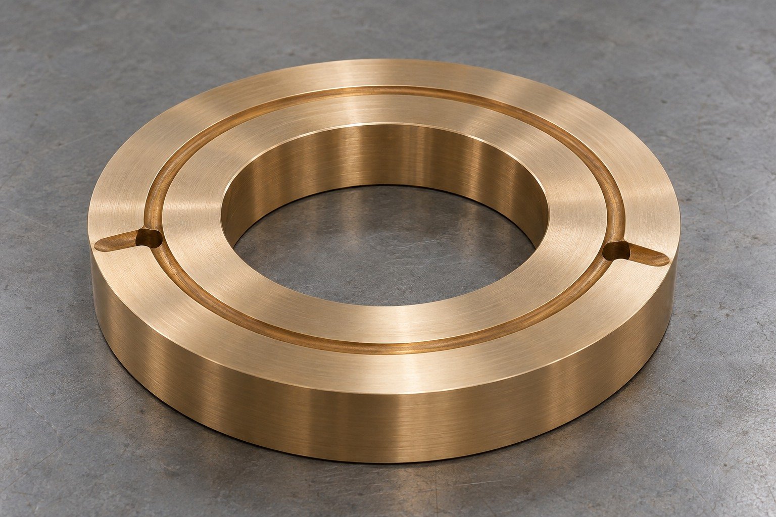
Agree marks, coating or masking, cleanliness and individual protection around the actual mating surface. Confirm dimensions after any specified finishing.
Define shaft, housing and working surface.
Agree stock, support and lubrication access.
Inspect the defined final state.
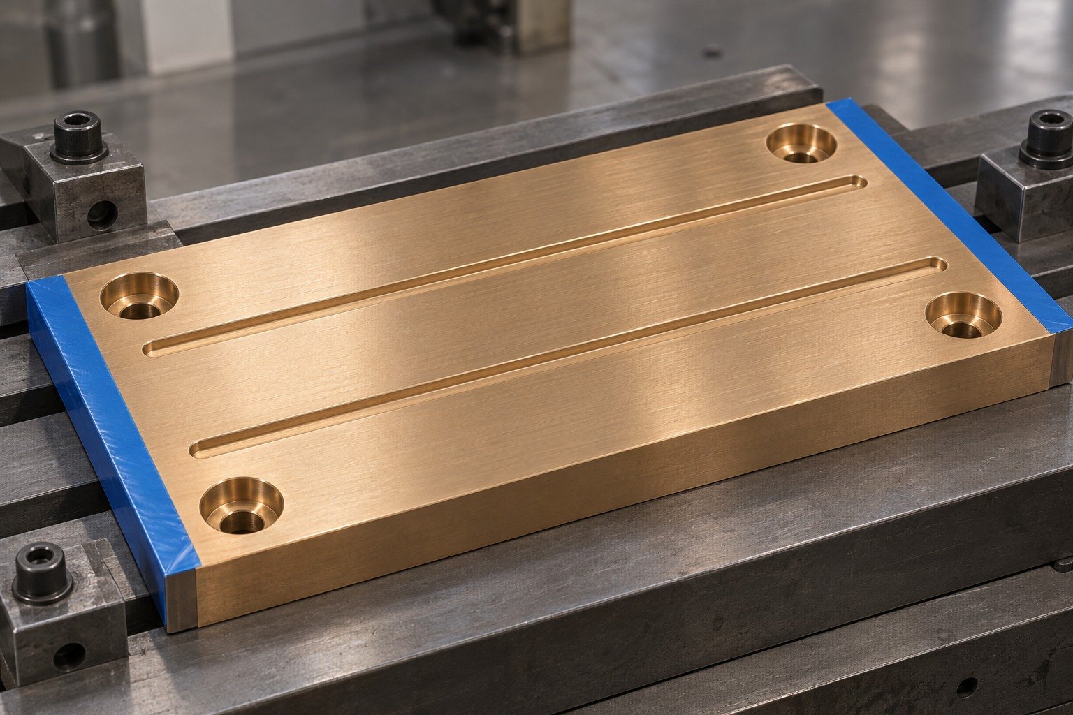
A C93200 bushing manufacturer or C93200 bronze bearing manufacturer review should identify the final bore, mounting relationship, sampling and evidence your receiving team needs.
Define shaft, housing and working surface.
Agree stock, support and lubrication access.
Inspect the defined final state.


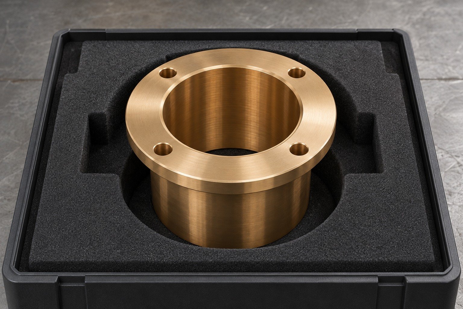
Agree marks, cleanliness, edge condition and protection. Review any finish against your final mating geometry.
Surface Finishing →| Your decision | What to compare |
|---|---|
| Material system | C93200 is leaded tin bronze; C95400 is aluminum bronze. |
| Final assembly | Review shaft, housing, load, movement and lubrication. |
| Machining route | Compare exact stock, usable allowance, support and final surface. |
| Drawing approval | Approve the complete specification before substitution. |
An indicative cutting index does not rank bearing life or approve a replacement. Keep the material and functional requirements together.
Compare Bronze Alloys →Product identity and ordered requirements.
Complete route and locating relationship.
Final working surfaces and evidence.
Identify ordered specification, revision, casting route, lot identity and certificate contents before the first cut.
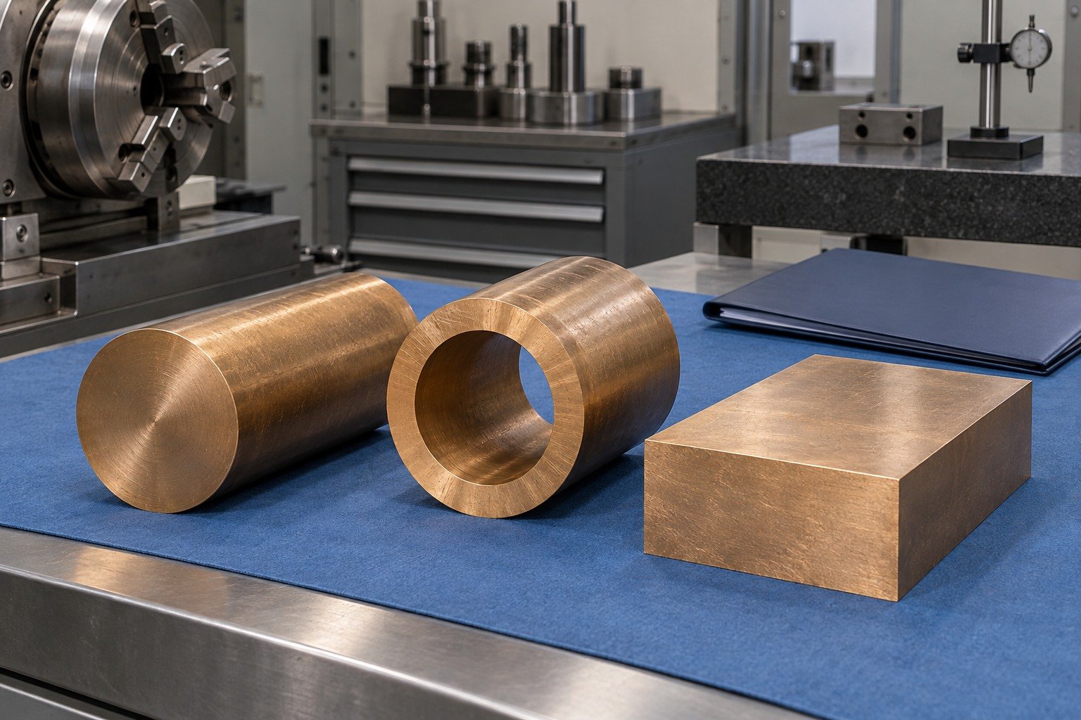
Check complete first-sample dimensions, locating surfaces and usable allowance before repeating the route.
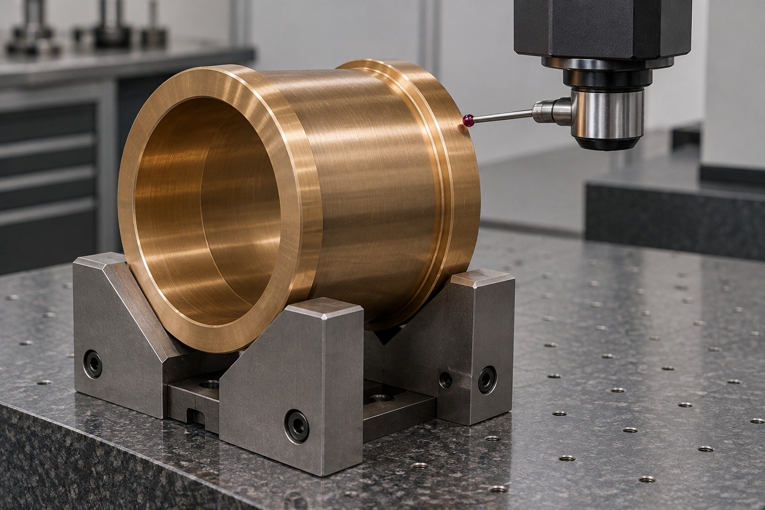
Verify the final bore, thrust face or plate datum in the agreed measurement state. Dimensional records and functional tests answer different questions.
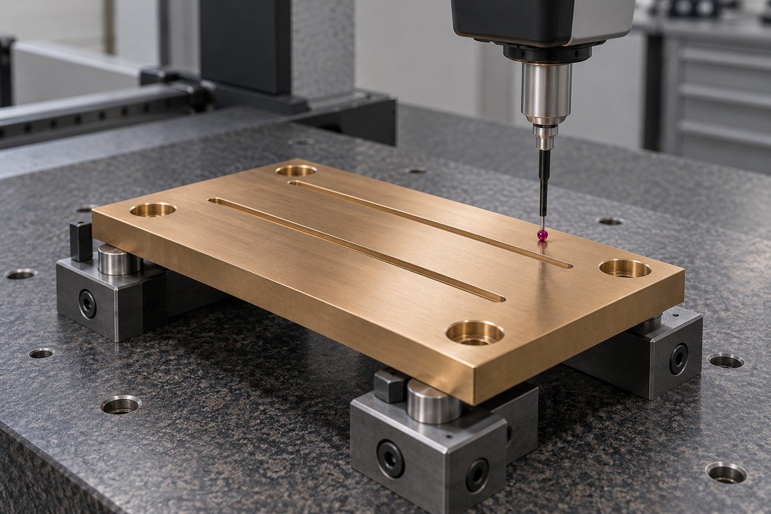
Agree protection, cleanliness, lot identity and receiving documents for your actual mating surfaces.
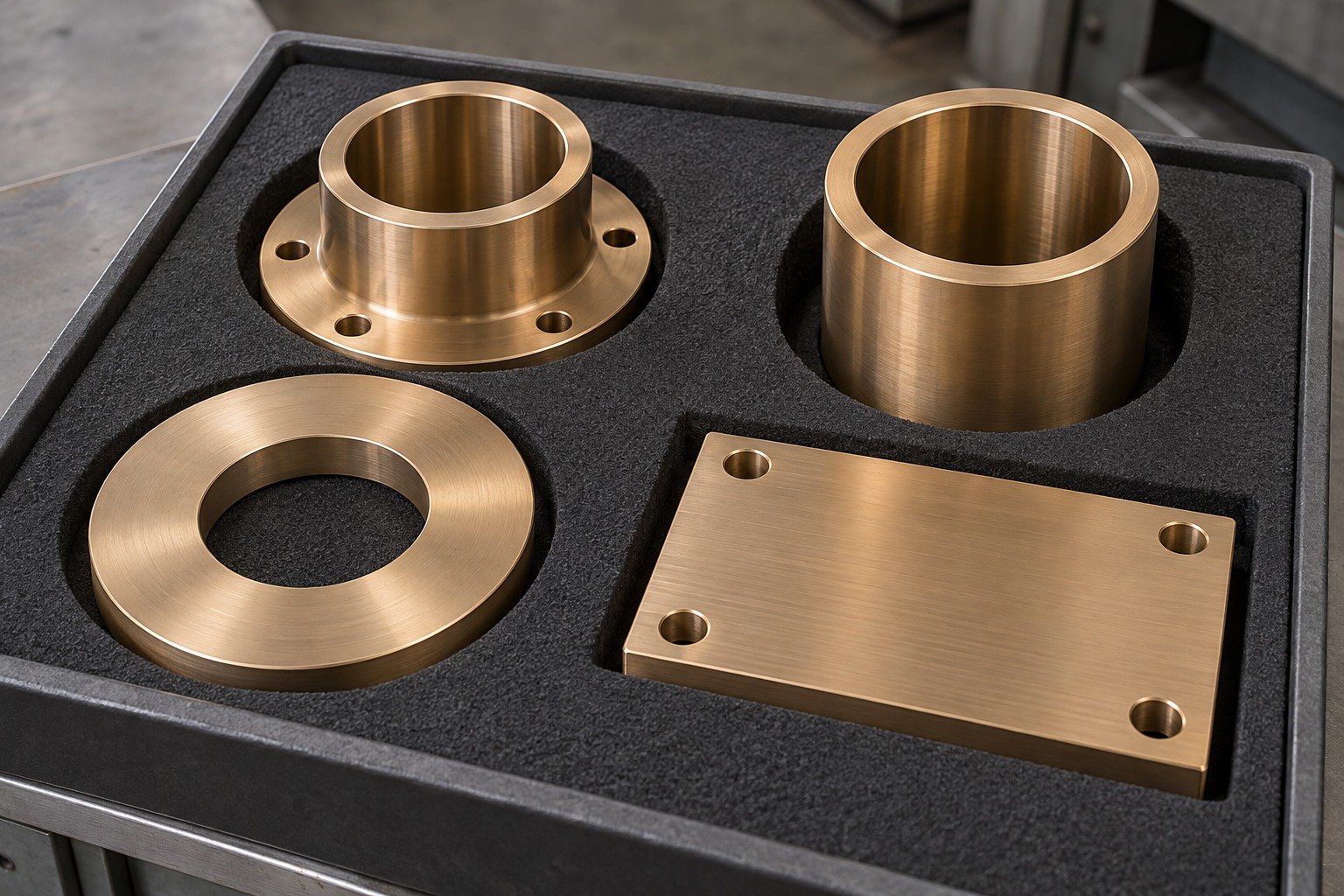

Connect China manufacturing with Dallas-area coordination for drawing review, sample decisions and delivery requirements.
Your C93200 machining quote should compare the same stock route, drawing revision, free or installed acceptance and receiving evidence.
C93200 is a leaded cast tin-bronze designation used for bearing-part reviews. Specify the exact product standard, casting route and final working interface.
SAE 660 is a common supplier name associated with C93200. Retain the complete ordered product specification, revision, chemistry and casting route; the short name alone is not acceptance.
Do not assume it is. Solid cast C93200 is not automatically an oil-impregnated sintered bearing. Define lubrication supply, replenishment, load, movement and actual service conditions.
Yes. The selected Concast continuous-cast chemistry gives Pb6–8%. Confirm the ordered material and application requirements before approval.
For SAE 660 bronze machining tolerances, state feature limits, datums and free or installed acceptance. Your quote confirms reviewed geometry and inspection scope; no universal tolerance is promised.
Provide actual shaft and housing sizes, component wall, temperature, movement, lubrication and measurement state. Agree drawing limits for the final assembly instead of choosing one alloy-wide clearance.
Review it as a material and lubrication-system change. Confirm stock route, lubricant delivery, fit, working conditions and drawing-authority approval before substitution.
Provide CAD and controlled drawing, ordered material and casting specification, stock and quantities, shaft and housing details, lubrication layout, final surface and required receiving evidence.





