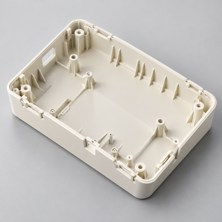
Injection Molding
Tooling and molding for your repeat plastic parts.
From prototype to production, coordinated manufacturing solutions for your custom parts.
View All Services →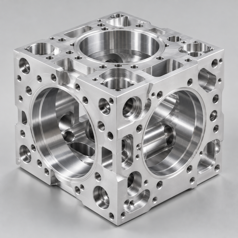
Precision parts for your tight tolerances and complex geometry.
Tooling and molding for your repeat plastic parts.
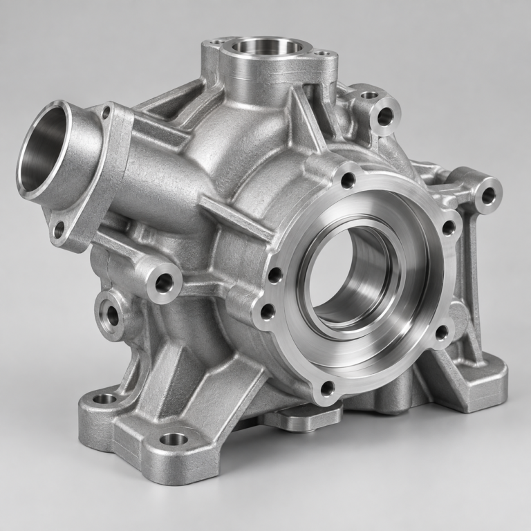
Metal casting options for your part and production volume.
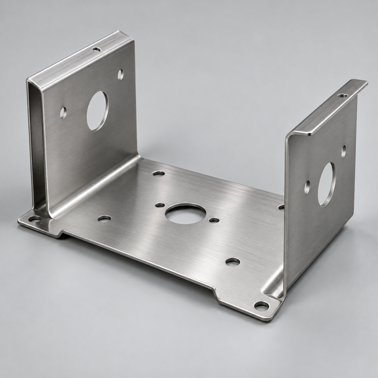
Cutting, forming and welding for your fabricated parts.
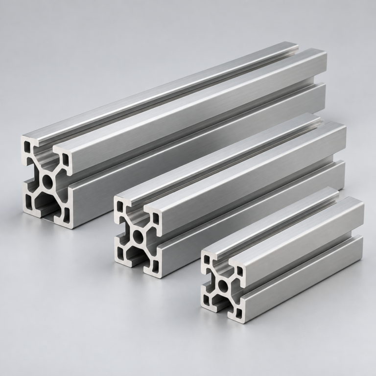
Custom profiles for your section, length and finish requirements.
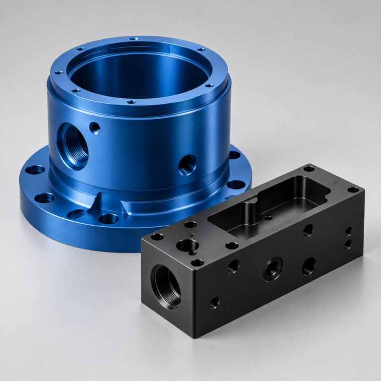
Finishes for your appearance, corrosion and wear requirements.
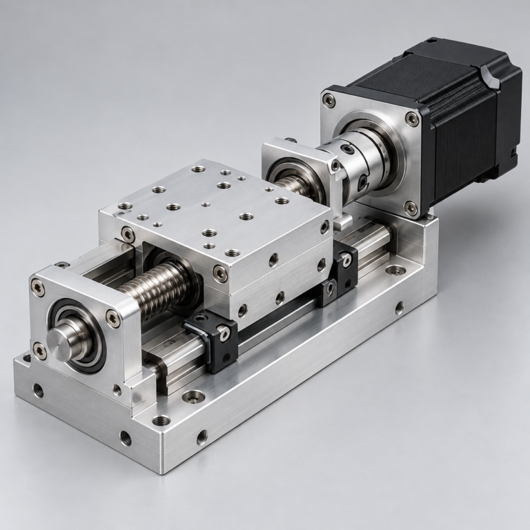
Sub-assemblies and final builds for your production program.
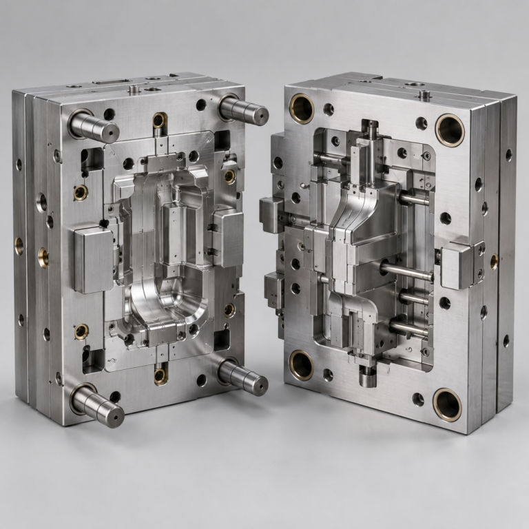
Production tooling built around your process and volume.
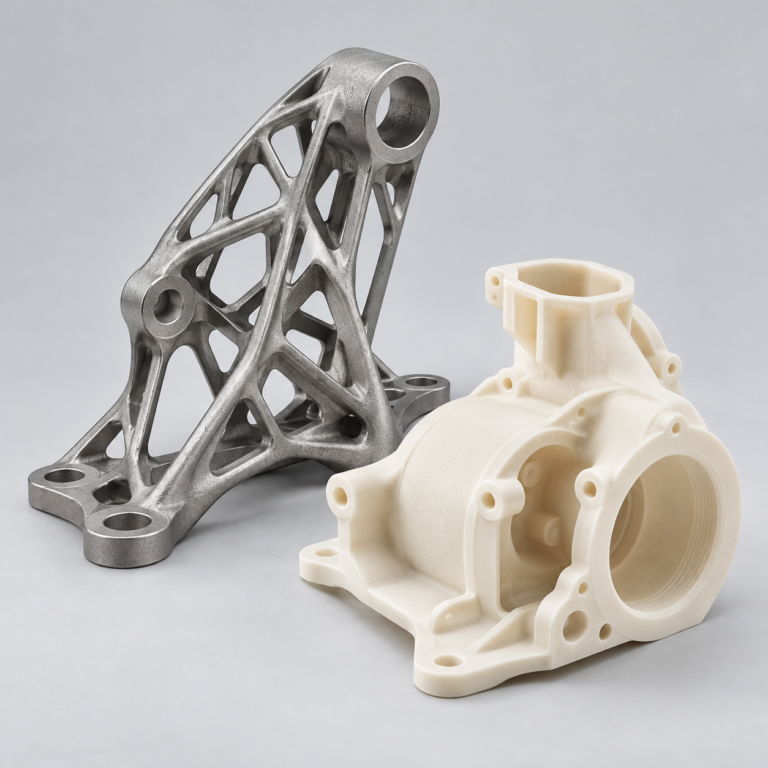
Prototype parts to check fit, function and design.
DFM, process planning and production support for your project.
Inspection, documentation, inventory and delivery planning for your program.
Choose air- or liquid-cooling components around your thermal and mechanical requirements.
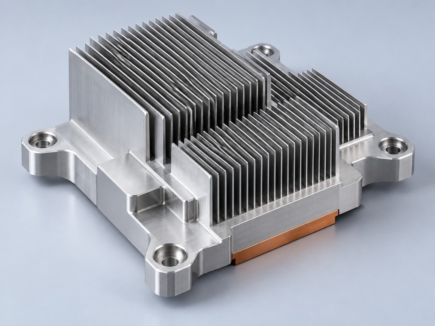
Manufacturing support for your cold plates, manifolds and cooling assemblies.
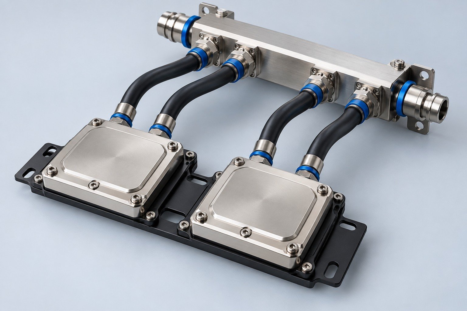
Find components for your power electronics, energy, laser and telecom application.
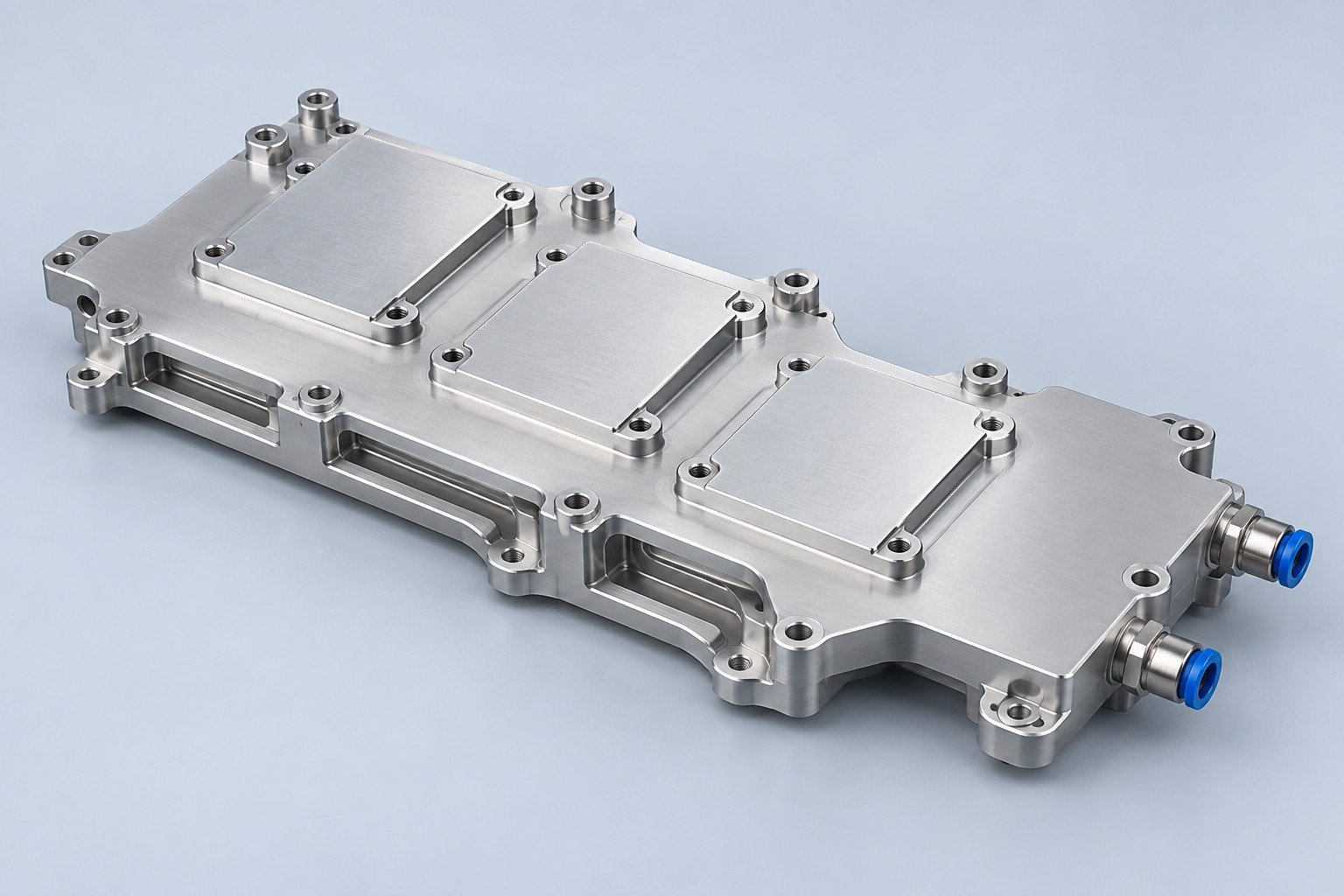
Components for your electronic systems.
Start with your functional and quality requirements.
Build around your operating environment.
From prototype to production, review material performance, manufacturability and cost for your part.
Review grade, temper and finish for your metal parts.
 AluminumStrength, weight and machining›
 Stainless SteelCorrosion and finish requirements›
 Carbon & Alloy SteelDiscuss grade and heat treatment›
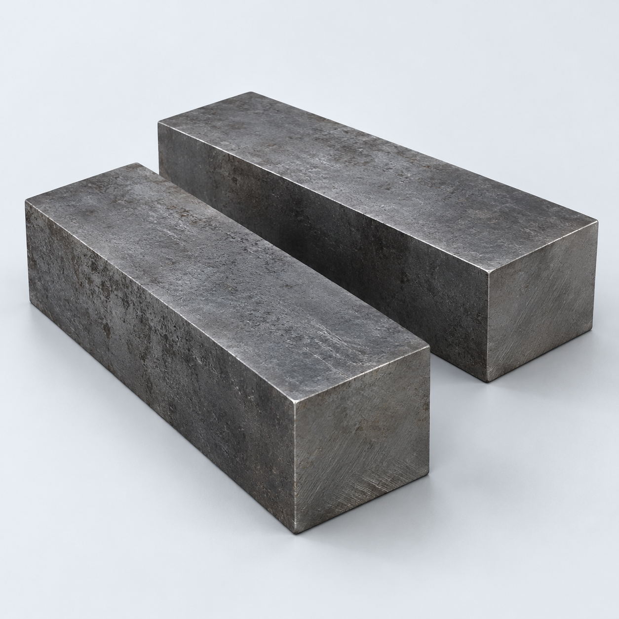 Tool SteelDiscuss tooling and wear needs›
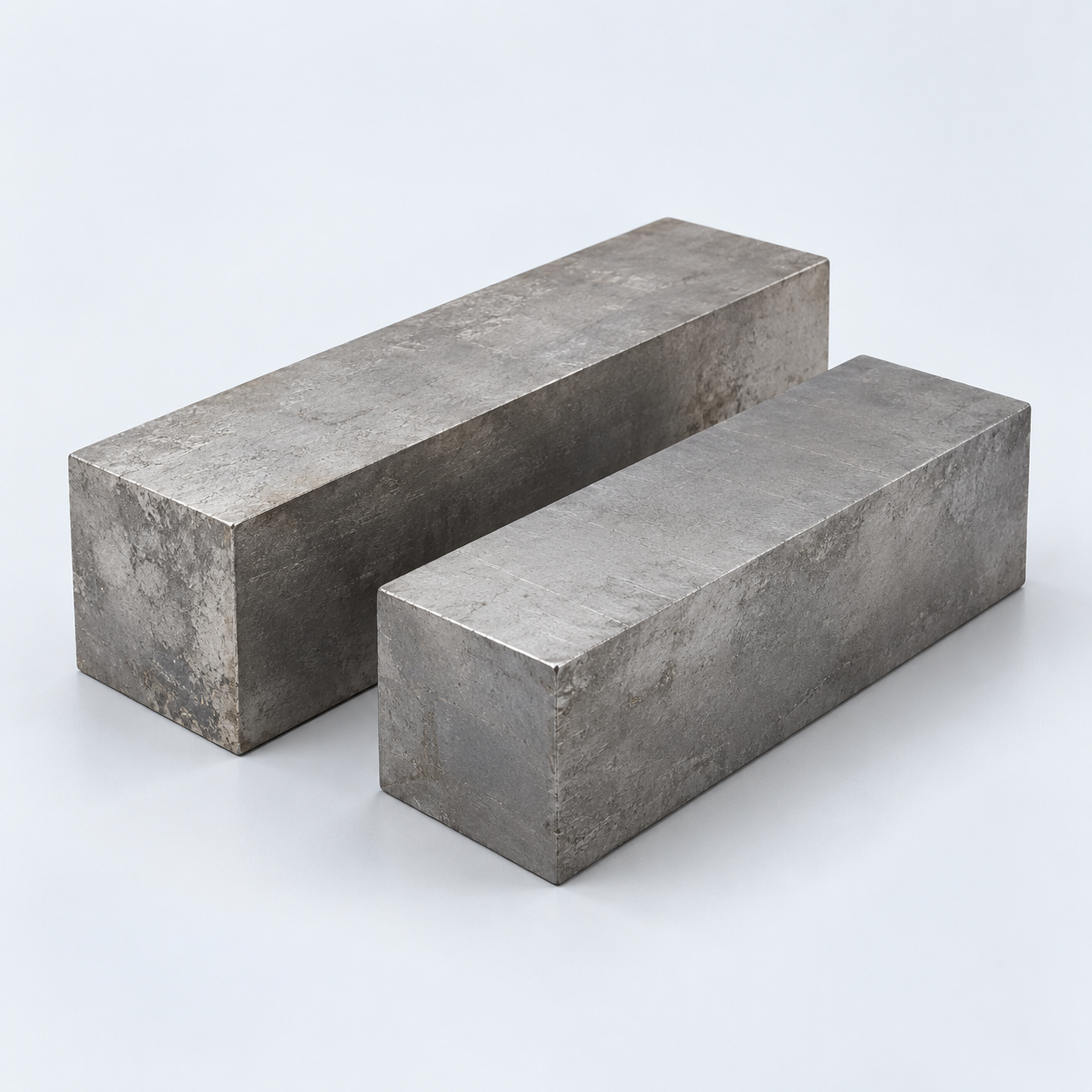 TitaniumReview grade and part geometry›
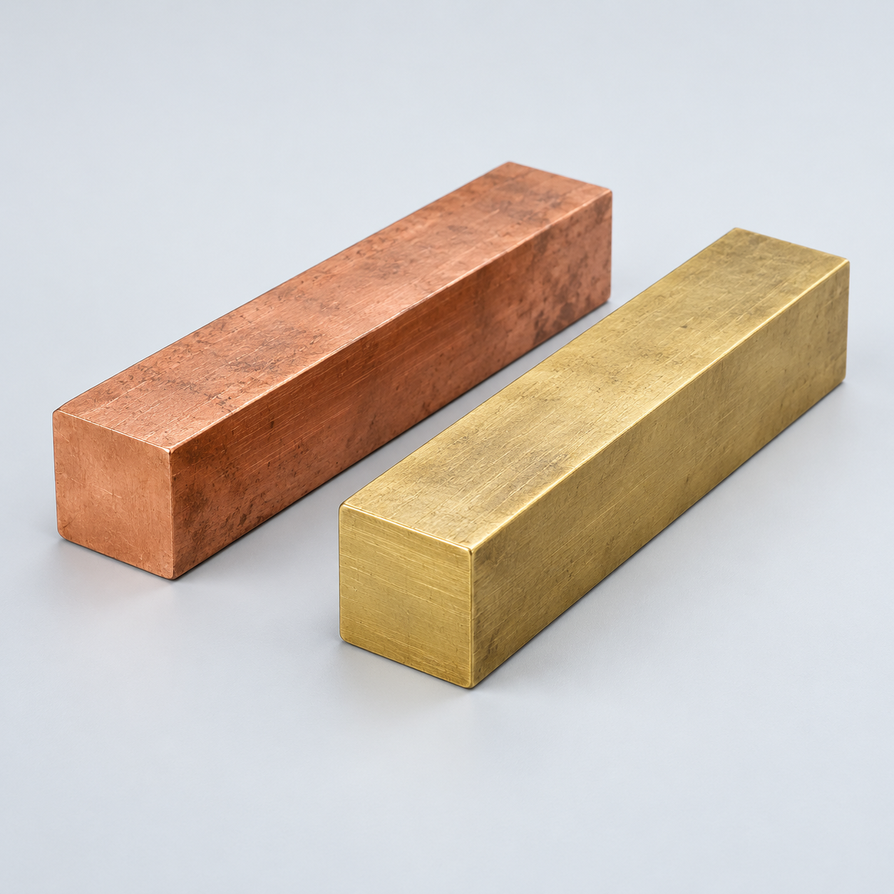 Copper & Brass & BronzeDiscuss conductivity and machining›
Match your polymer to function, process and environment.
 ABSReview enclosure and molding needs›
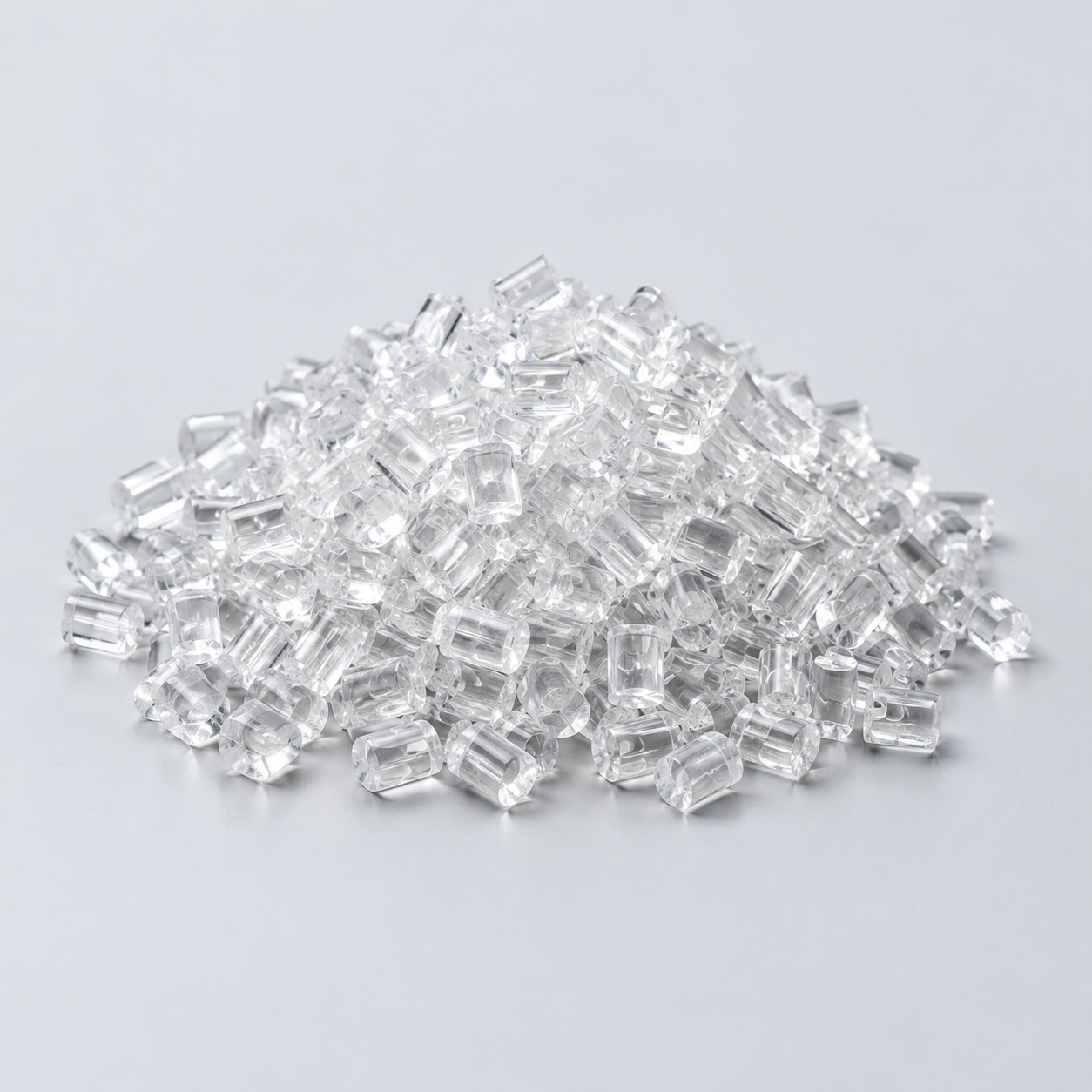 Polycarbonate (PC)Discuss clarity and impact needs›
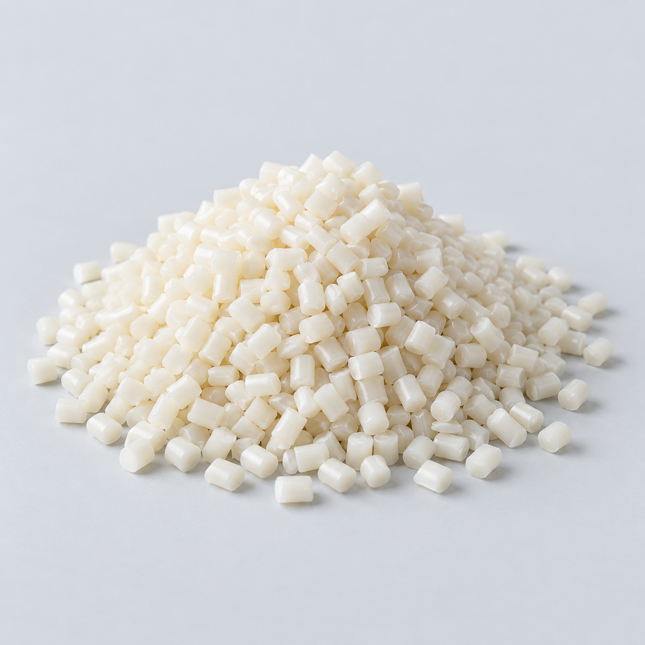 Nylon (PA)Review moisture and wear conditions›
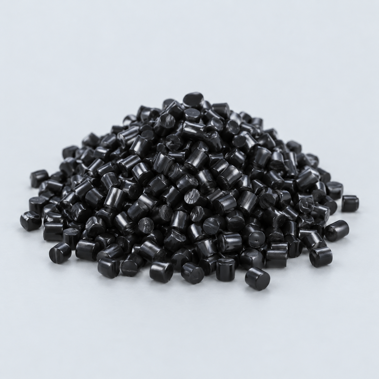 POM / AcetalReview fit and sliding features›
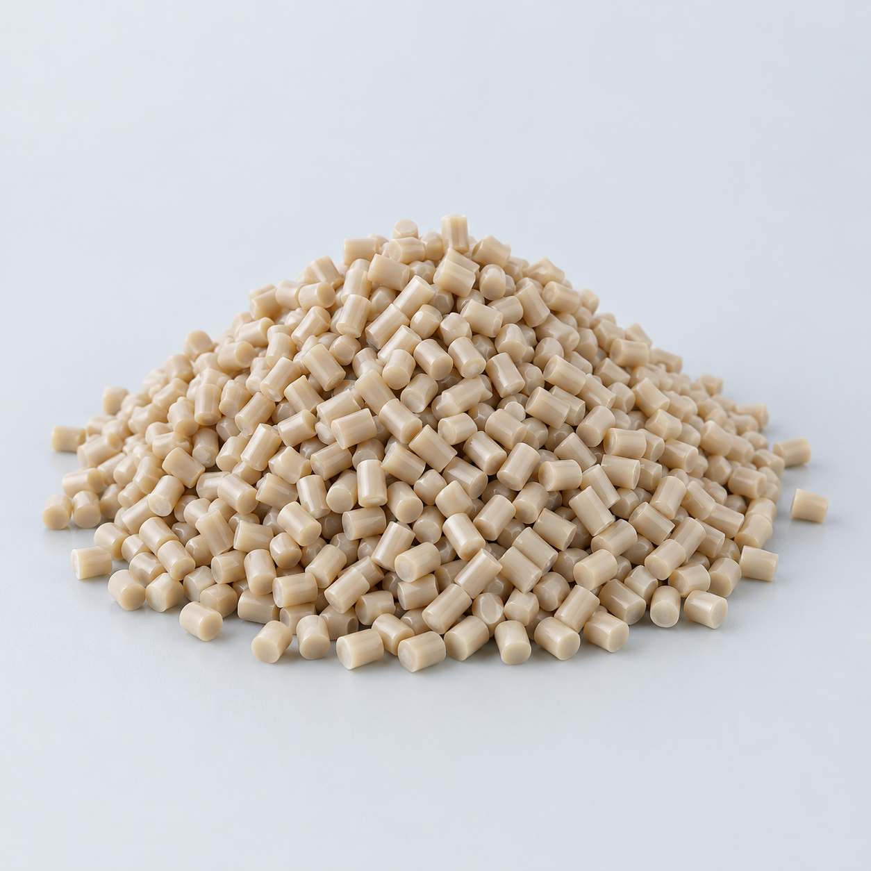 PEEKDiscuss operating conditions›
 PTFEReview friction and chemical exposure›
 ULTEM / PEIDiscuss thermal and electrical needs›
Confirm grade availability and application requirements.
 Silicone / LSRDiscuss flexible component needs›
 TPU / TPEReview flexibility and processing›
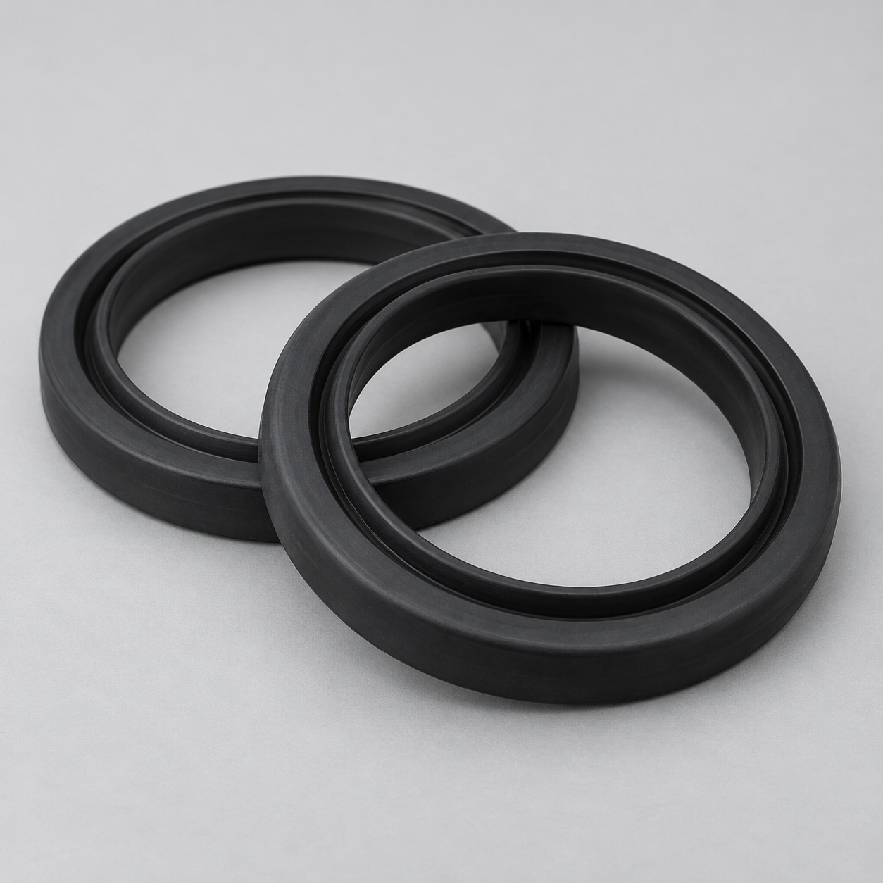 EPDMReview weathering and chemical exposure.›
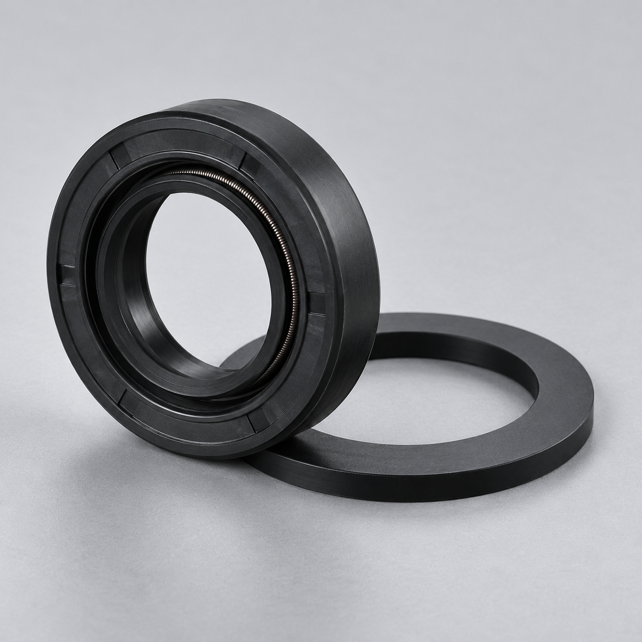 NBRReview oil and fuel exposure.›
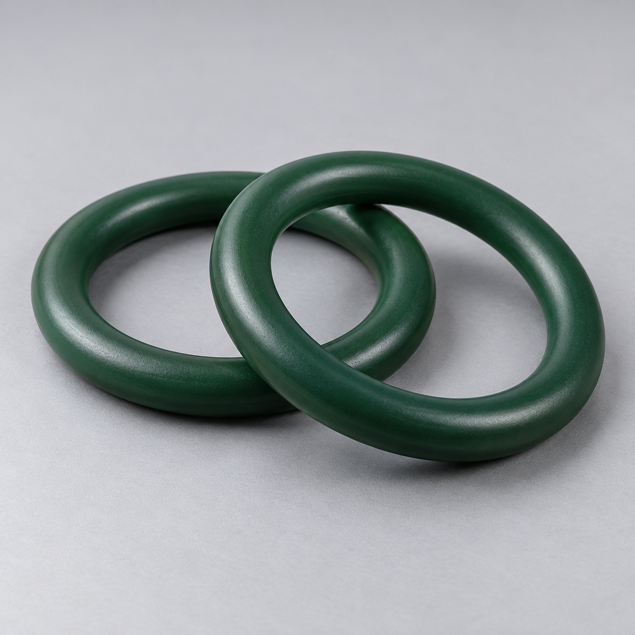 FKMReview temperature and chemical exposure.›
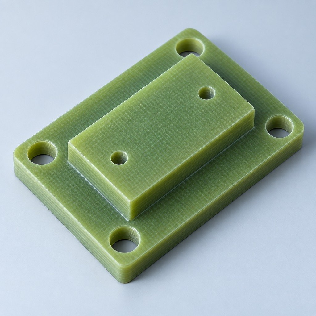 G10 / FR4Review insulation and laminate needs›
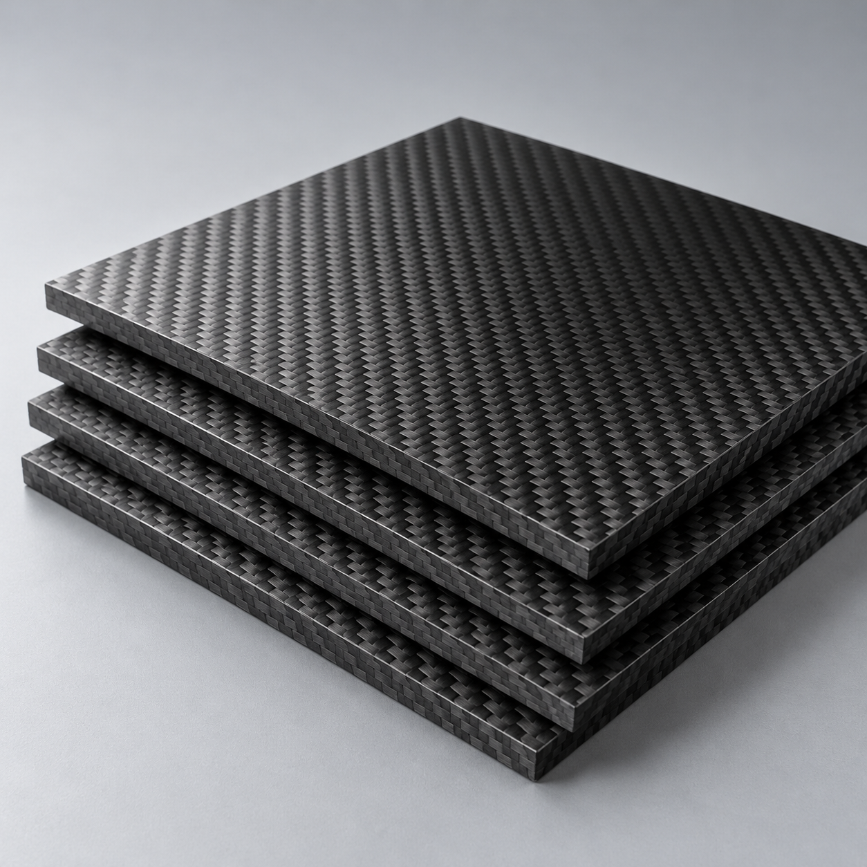 CompositesReview stiffness, weight and laminate.›Customer-Specified MaterialsConfirm your grade and requirements.›Other Specialty MaterialsDiscuss your application and grade.›
Practical guidance for your part geometry and material decisions.
Prepare your process, budget and sourcing questions.
Build your knowledge before production.
Learn who we are and how we operate.
Find our U.S. support team or start a conversation.
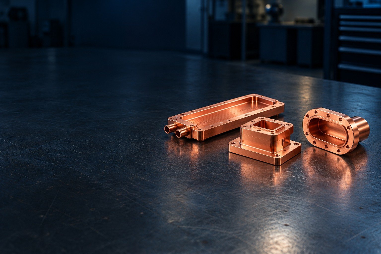
For your C101 copper machining inquiry, specify UNS C10100 OFE, the supplied state and final working surfaces. Connect thermal, RF or vacuum geometry to the inspection your assembly needs.
For C10100 copper machining and oxygen free electronic copper machining, name the standard system first. This page concerns UNS C10100 OFE copper; a bare C101 label can mean a different material on a UK drawing.
| Purchasing identifier | Your reference |
|---|---|
| United States | UNS C10100 · oxygen-free electronic copper / OFE |
| European comparison | Cu-OFE / CW009A · confirm full product standard |
| Naming caution | Old UK BS C101 normally maps to Cu-ETP / CW004A; do not assume UNS C10100. |
| Selected element | CDA limit · wt.% |
|---|---|
| Copper · excluding Ag | ≥99.99 |
| Oxygen | ≤0.0005 · 5 ppm |
| Silver | ≤0.0025 |
| Phosphorus | ≤0.0003 |
Selected CDA limits only; the complete impurity table and ordered product specification govern. Copper is exclusive of silver in the CDA C10100 definition. Not a lot analysis.
For C101 copper conductivity, the CDA annealed reference is at least 101% IACS at 20°C. The selected bedra thermal reference is 391 W/(m·K) at 20°C. Neither value establishes a finished cold-plate rating, RF loss, contact resistance or vacuum leak performance.
CDA annealed reference · % IACS at 20°C · common scale 0–110
CDA grade reference · ppm by mass · common scale 0–10
Selected CDA annealed conductivity minima and grade oxygen maxima. The conductivity minimum differs by 1 IACS percentage point, not a promised 1% assembly improvement. An oxygen limit is not a measured value or leak guarantee. Confirm stock form, condition and complete specification before substitution.
CDA C10100 ↗ CDA C10200 ↗ bedra Cu-OFE / CW009A ↗ Copper Information Center · old BS designations ↗
Select a thermal, RF or vacuum geometry, then review the manufacturing and receiving decisions for your part.
For your C101 copper cold plates, define channel shape, remaining wall, port pads and sealing land before selecting a machining route. An open-channel concept is not a complete sealed cooling assembly.
| Your decision | What to define |
|---|---|
| Your fit | Channel-to-mounting datums, sealing land, wall requirement and port geometry. |
| Your route | Stock condition, support and finishing sequence. |
| Your approval | Final geometry, surface and receiving evidence. |
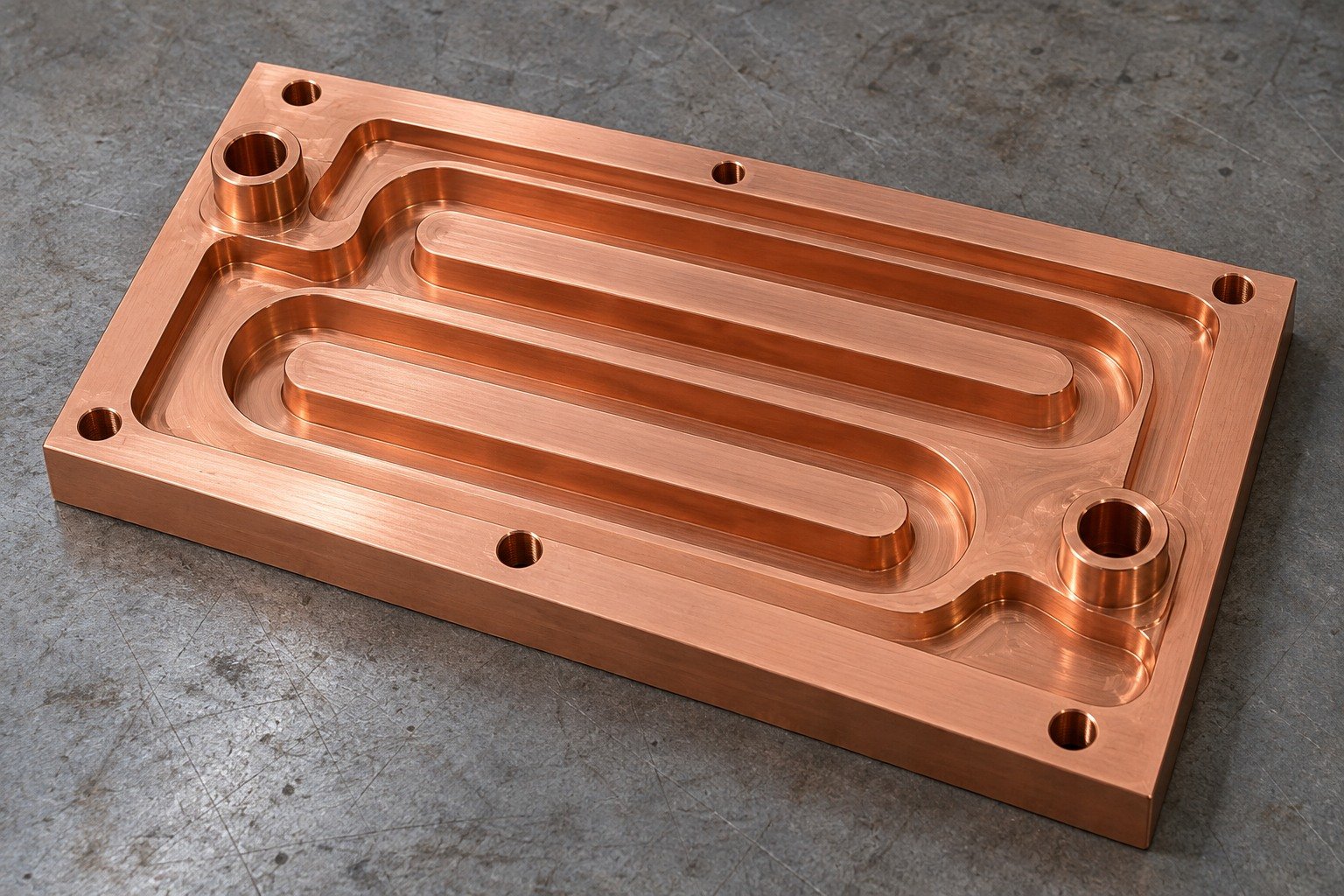
For C101 copper milling, review support beneath channels, cutter access and the sequence that protects the mating land.
| Your decision | What to define |
|---|---|
| Your fit | Channel-to-mounting datums, sealing land, wall requirement and port geometry. |
| Your route | Stock condition, support and finishing sequence. |
| Your approval | Final geometry, surface and receiving evidence. |
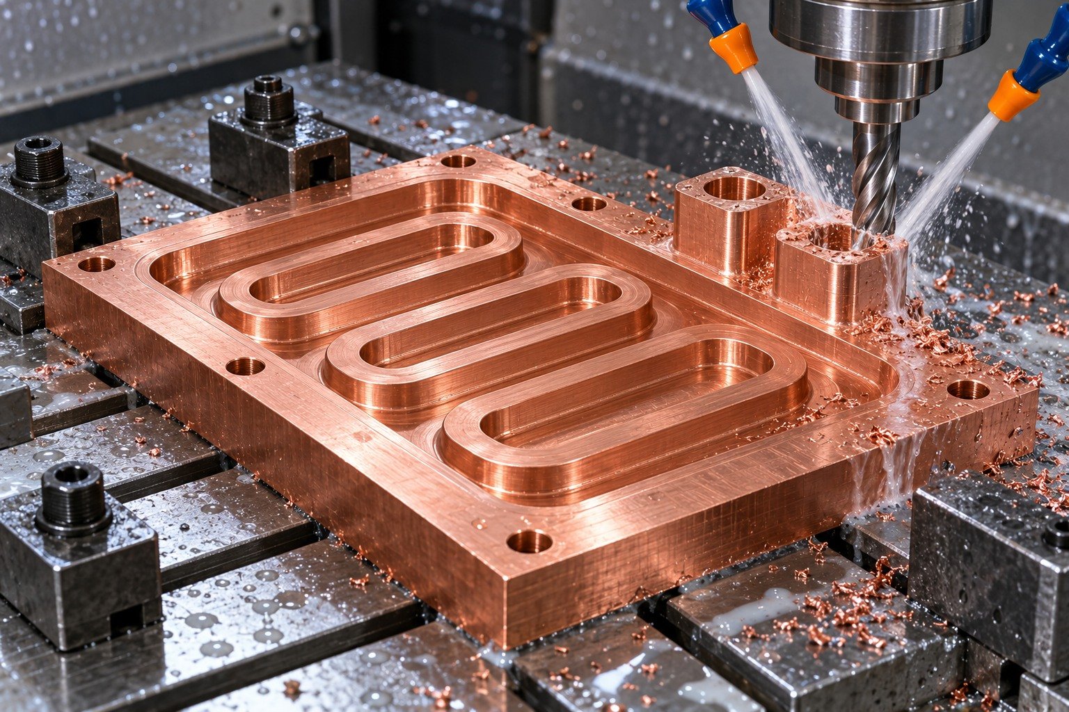
Specify product form and supplied temper. Agree any joining or cover-attachment route separately from the machined base.
| Your decision | What to define |
|---|---|
| Your fit | Channel-to-mounting datums, sealing land, wall requirement and port geometry. |
| Your route | Stock condition, support and finishing sequence. |
| Your approval | Final geometry, surface and receiving evidence. |
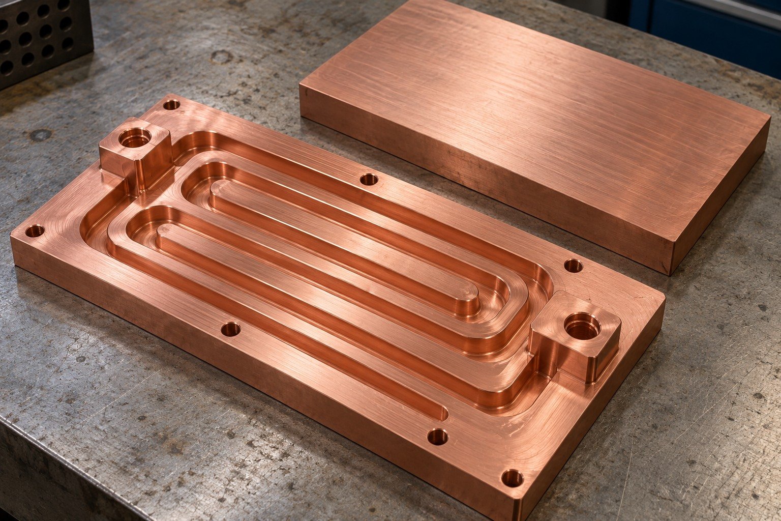
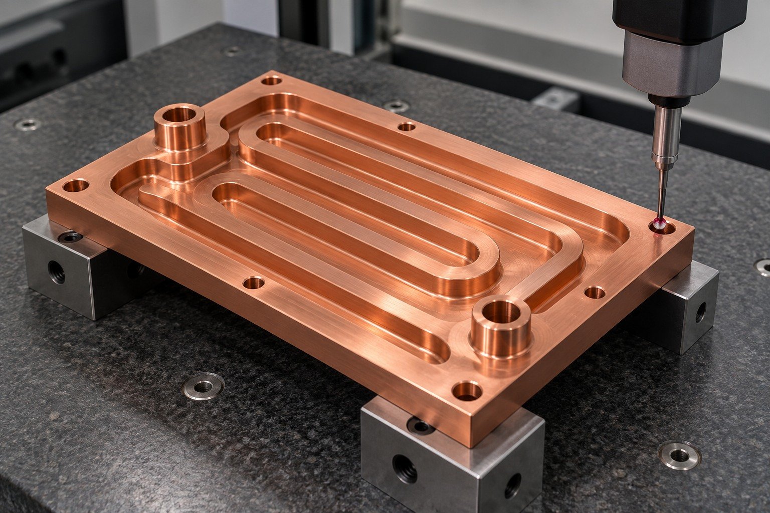
Inspect the finished channels and sealing datums. Any pressure, flow or thermal test needs a separately agreed procedure and scope.
| Your decision | What to define |
|---|---|
| Your fit | Channel-to-mounting datums, sealing land, wall requirement and port geometry. |
| Your route | Stock condition, support and finishing sequence. |
| Your approval | Final geometry, surface and receiving evidence. |
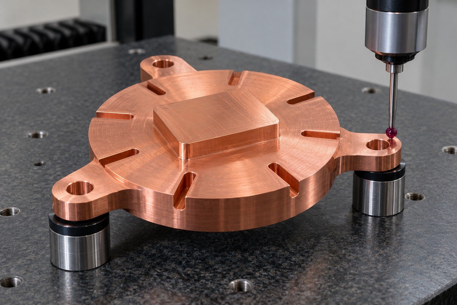
Review your C101 copper heat sinks around contact area, slot access, mounting ears and remaining base thickness. Material conductivity alone does not size your complete thermal system.
| Your decision | What to define |
|---|---|
| Your fit | Contact-plane requirement, radial-slot access, mounting pattern and base thickness. |
| Your route | Stock condition, support and finishing sequence. |
| Your approval | Final geometry, surface and receiving evidence. |
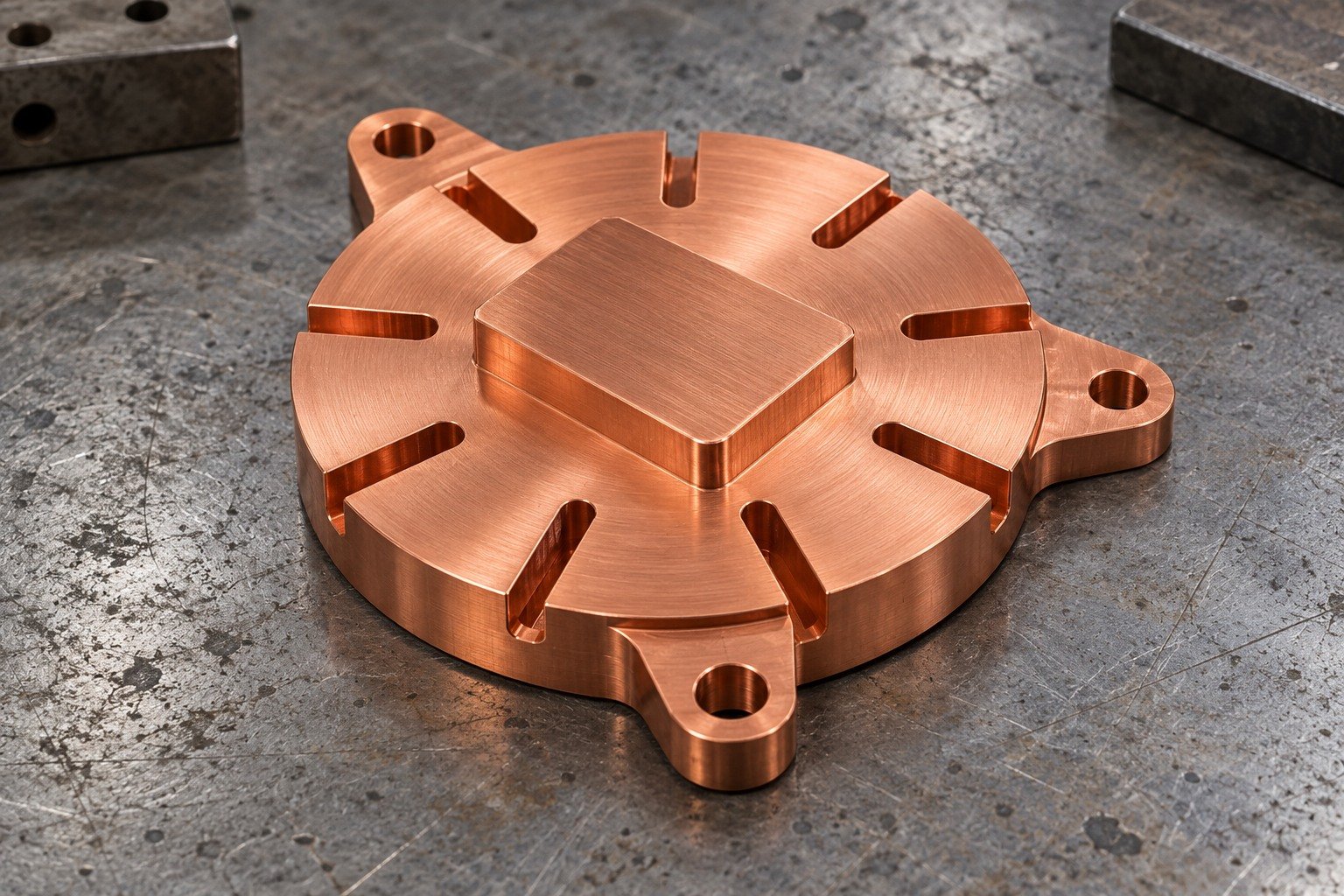
Support the base and mounting ears during machining. Keep clamping witness away from the working thermal-contact island.
| Your decision | What to define |
|---|---|
| Your fit | Contact-plane requirement, radial-slot access, mounting pattern and base thickness. |
| Your route | Stock condition, support and finishing sequence. |
| Your approval | Final geometry, surface and receiving evidence. |
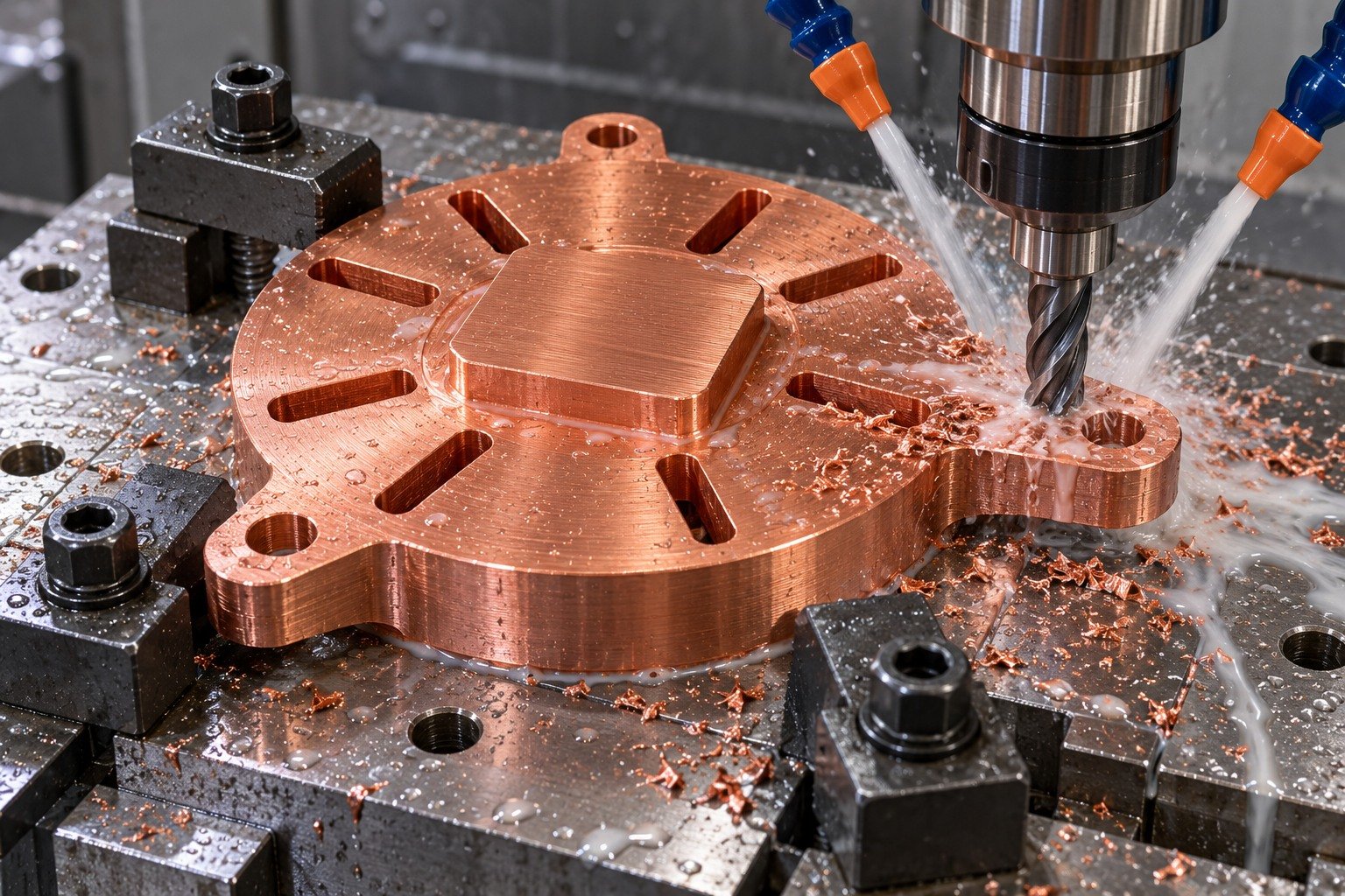
Confirm the stock state and final condition. A different temper needs review against distortion and the same finished drawing.
| Your decision | What to define |
|---|---|
| Your fit | Contact-plane requirement, radial-slot access, mounting pattern and base thickness. |
| Your route | Stock condition, support and finishing sequence. |
| Your approval | Final geometry, surface and receiving evidence. |
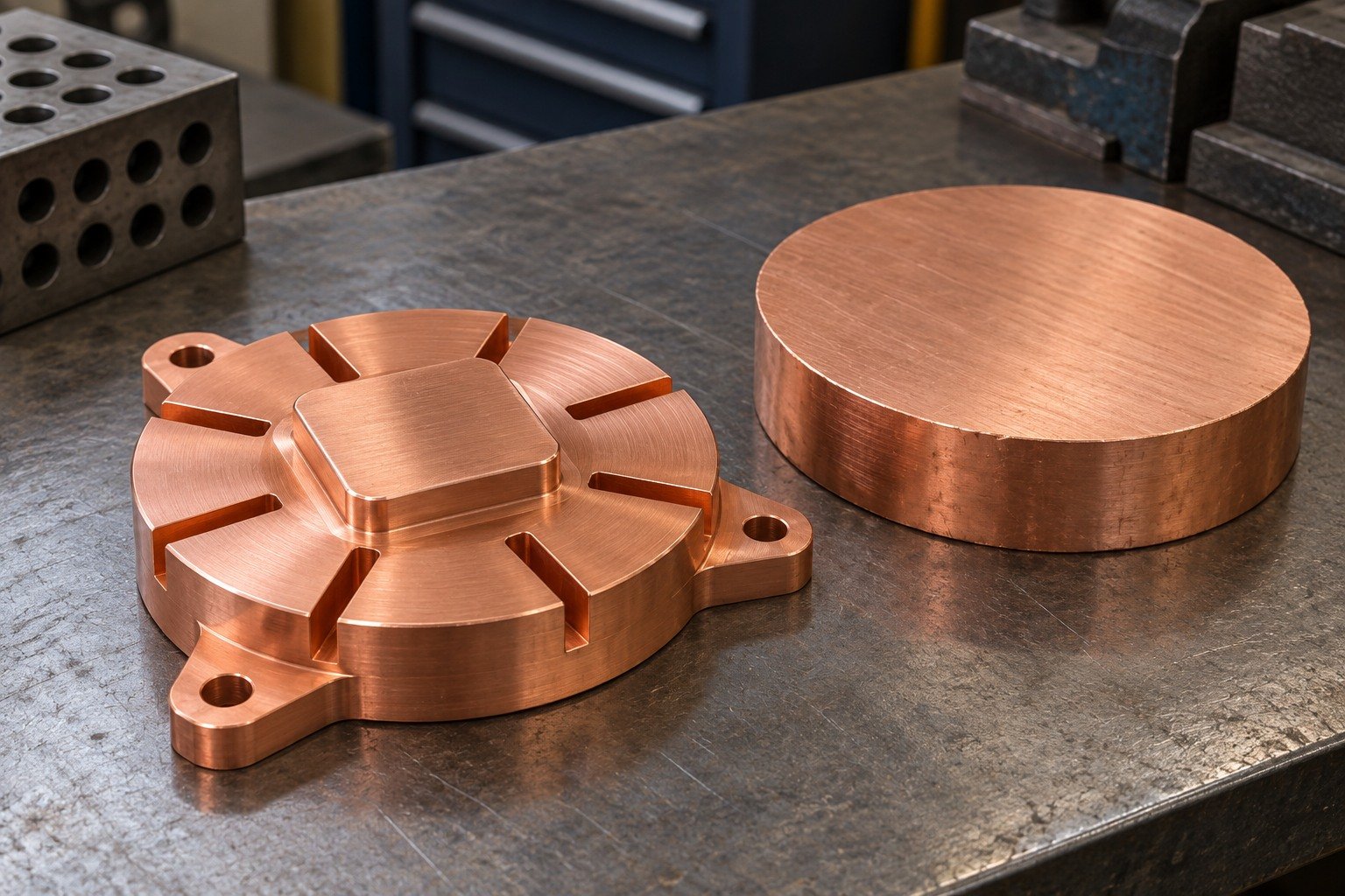
Verify the contact plane and mounting geometry after the complete route. Thermal-system testing is a separate acceptance decision.
| Your decision | What to define |
|---|---|
| Your fit | Contact-plane requirement, radial-slot access, mounting pattern and base thickness. |
| Your route | Stock condition, support and finishing sequence. |
| Your approval | Final geometry, surface and receiving evidence. |
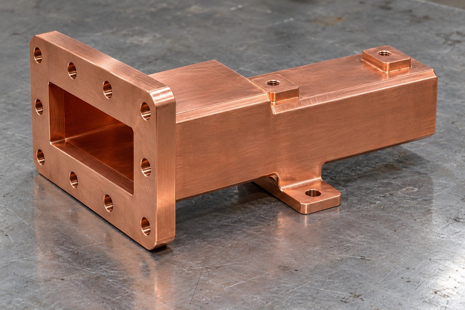
For C101 copper RF components, identify the rectangular aperture, flange land and mounting foot. Mark the surfaces that your RF design treats as functional.
| Your decision | What to define |
|---|---|
| Your fit | Aperture geometry, flange relationship, mounting datum and surface requirement. |
| Your route | Stock condition, support and finishing sequence. |
| Your approval | Final geometry, surface and receiving evidence. |
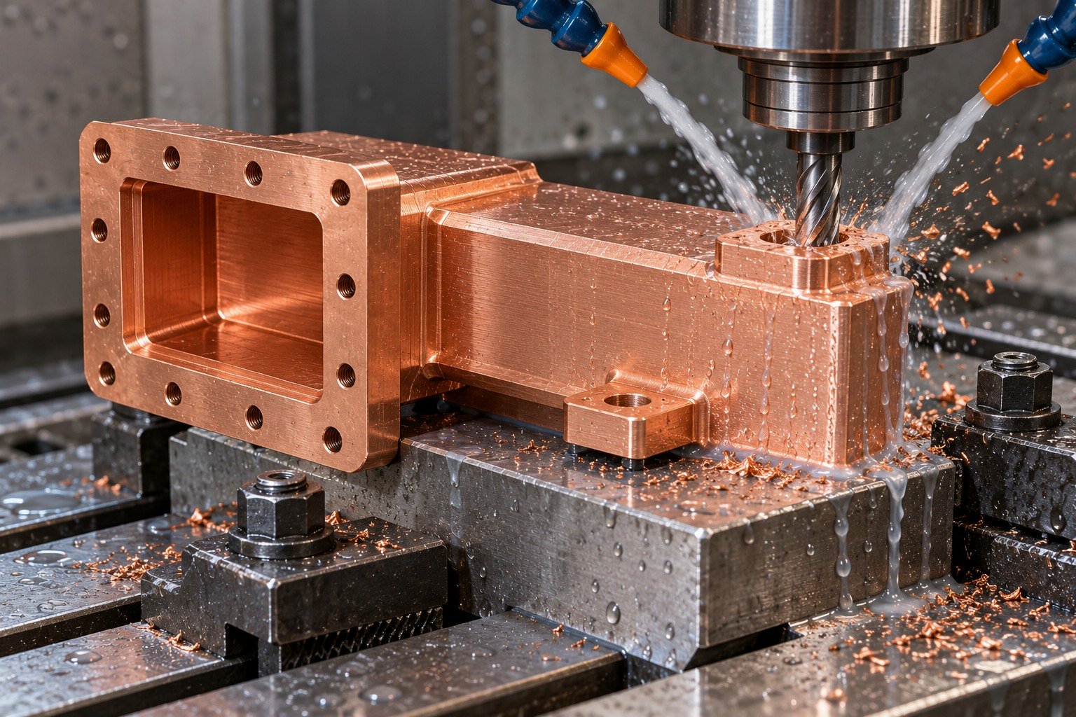
Review C101 copper drilling and C101 copper tapping with supported hole entry, chip escape and accessible internal edges.
| Your decision | What to define |
|---|---|
| Your fit | Aperture geometry, flange relationship, mounting datum and surface requirement. |
| Your route | Stock condition, support and finishing sequence. |
| Your approval | Final geometry, surface and receiving evidence. |
Confirm the actual UNS grade, product form and supplied condition; visual colour does not prove OFE chemistry.
| Your decision | What to define |
|---|---|
| Your fit | Aperture geometry, flange relationship, mounting datum and surface requirement. |
| Your route | Stock condition, support and finishing sequence. |
| Your approval | Final geometry, surface and receiving evidence. |
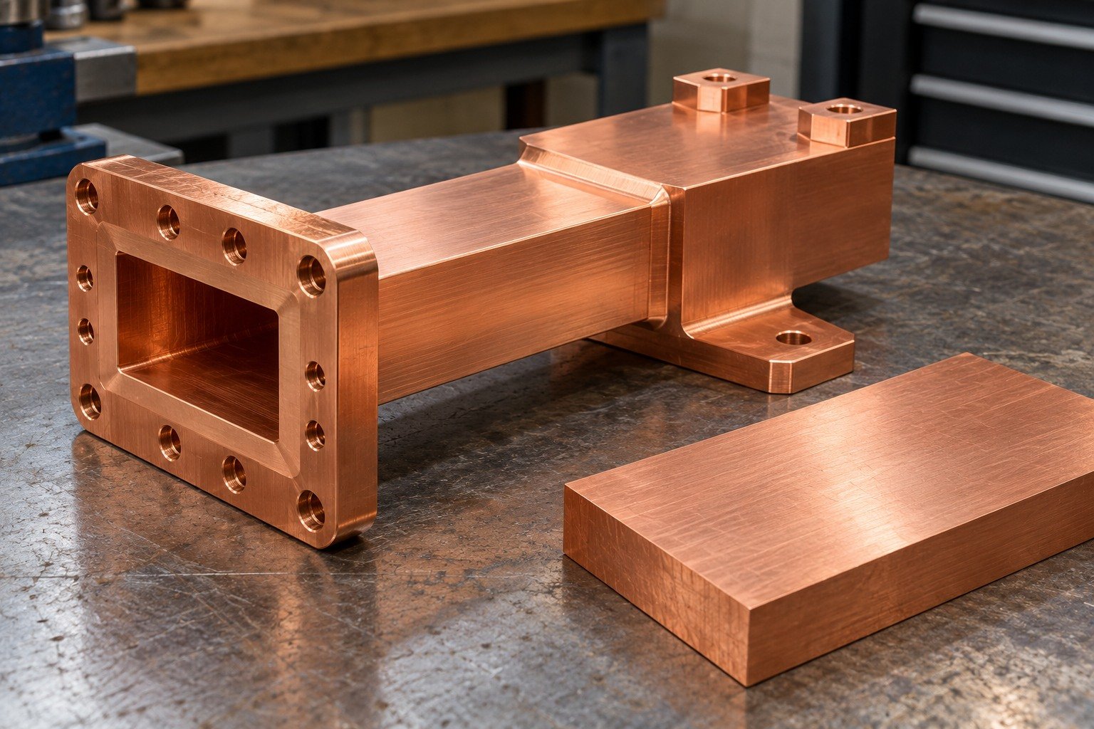
Verify aperture, flange and specified surface geometry. Dimensional inspection is not an RF performance qualification.
| Your decision | What to define |
|---|---|
| Your fit | Aperture geometry, flange relationship, mounting datum and surface requirement. |
| Your route | Stock condition, support and finishing sequence. |
| Your approval | Final geometry, surface and receiving evidence. |
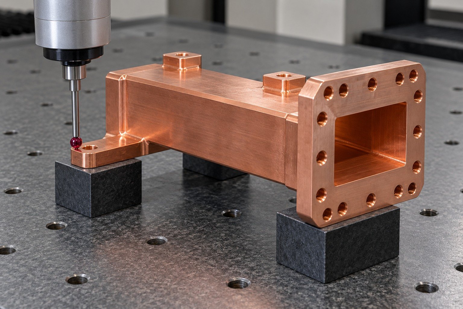
For your C101 copper vacuum components, define seal land, mounting pattern, neck geometry and cleanliness. The material designation does not establish a leak rate or vacuum classification.
| Your decision | What to define |
|---|---|
| Your fit | Seal geometry, flange datums, neck wall and accepted surface condition. |
| Your route | Stock condition, support and finishing sequence. |
| Your approval | Final geometry, surface and receiving evidence. |
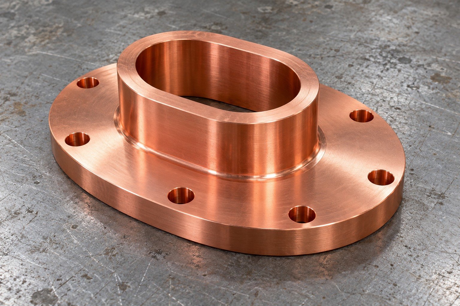
For C101 copper turning, review short supported engagement and protection of the finished sealing land.
| Your decision | What to define |
|---|---|
| Your fit | Seal geometry, flange datums, neck wall and accepted surface condition. |
| Your route | Stock condition, support and finishing sequence. |
| Your approval | Final geometry, surface and receiving evidence. |
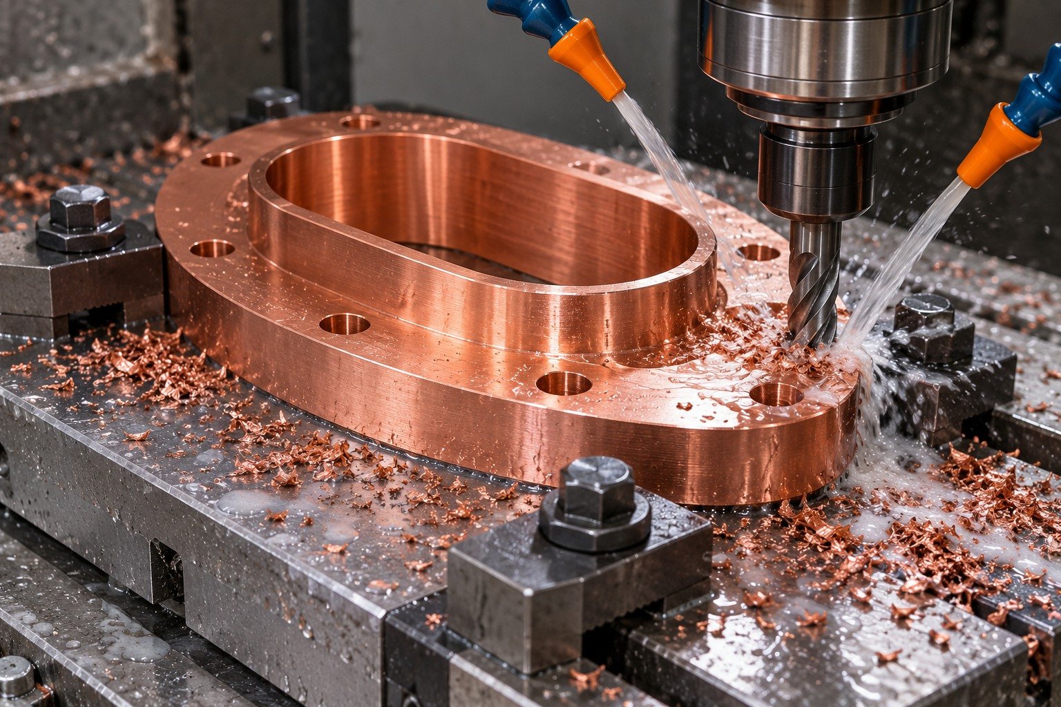
Specify the supplied material, any joining route and final cleaning requirement. Agree handling and packaging for the working surfaces.
| Your decision | What to define |
|---|---|
| Your fit | Seal geometry, flange datums, neck wall and accepted surface condition. |
| Your route | Stock condition, support and finishing sequence. |
| Your approval | Final geometry, surface and receiving evidence. |
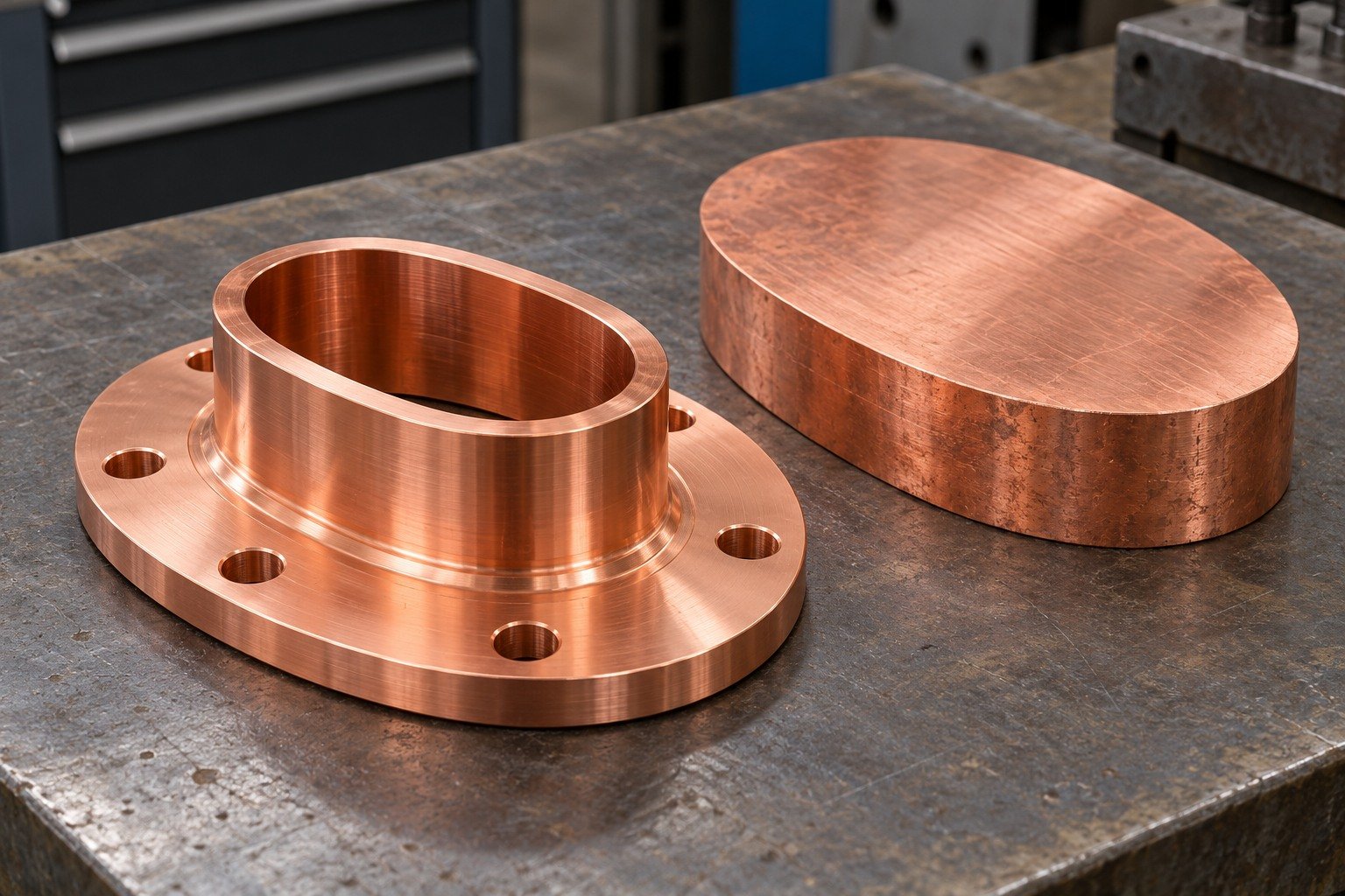
Inspect final seal datums and accepted edges. Any leak, cleanliness or outgassing test requires a defined method and agreed responsibility.
| Your decision | What to define |
|---|---|
| Your fit | Seal geometry, flange datums, neck wall and accepted surface condition. |
| Your route | Stock condition, support and finishing sequence. |
| Your approval | Final geometry, surface and receiving evidence. |
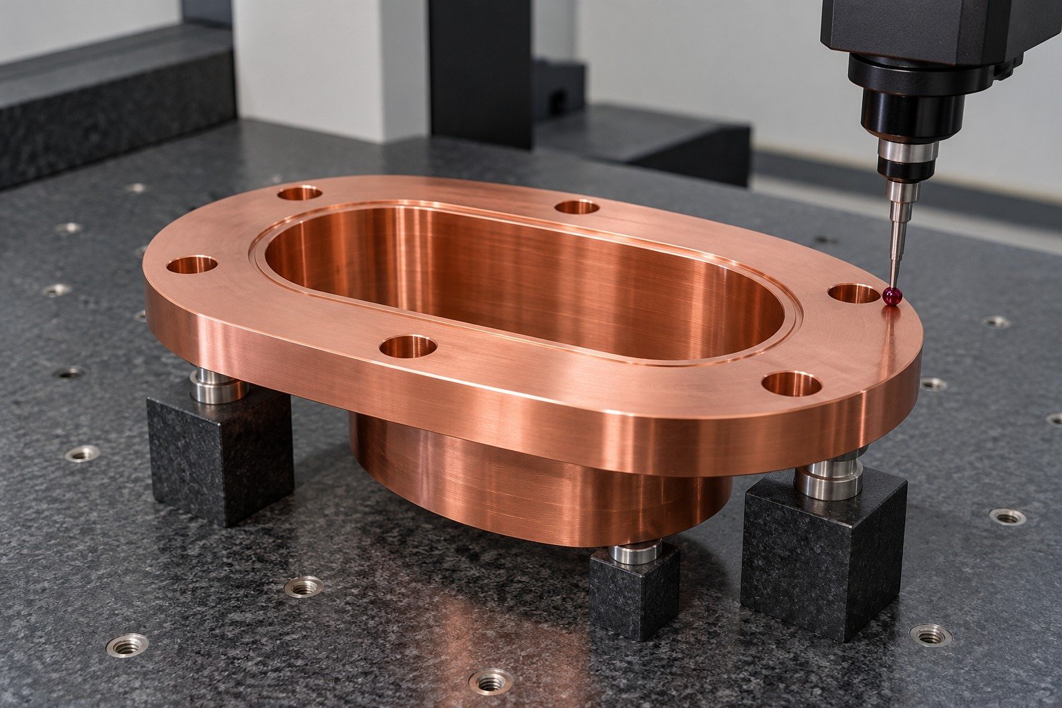
For your C101 copper machining services review, connect cutting, edge removal, cleaning and inspection to the same drawing revision. Your quote confirms accepted operations, quantities and evidence.
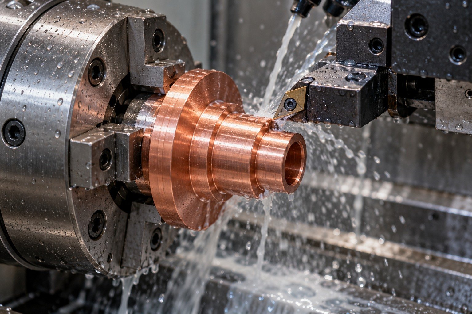
Review shoulders, bore access and support around finished connector lands.
Explore the Process →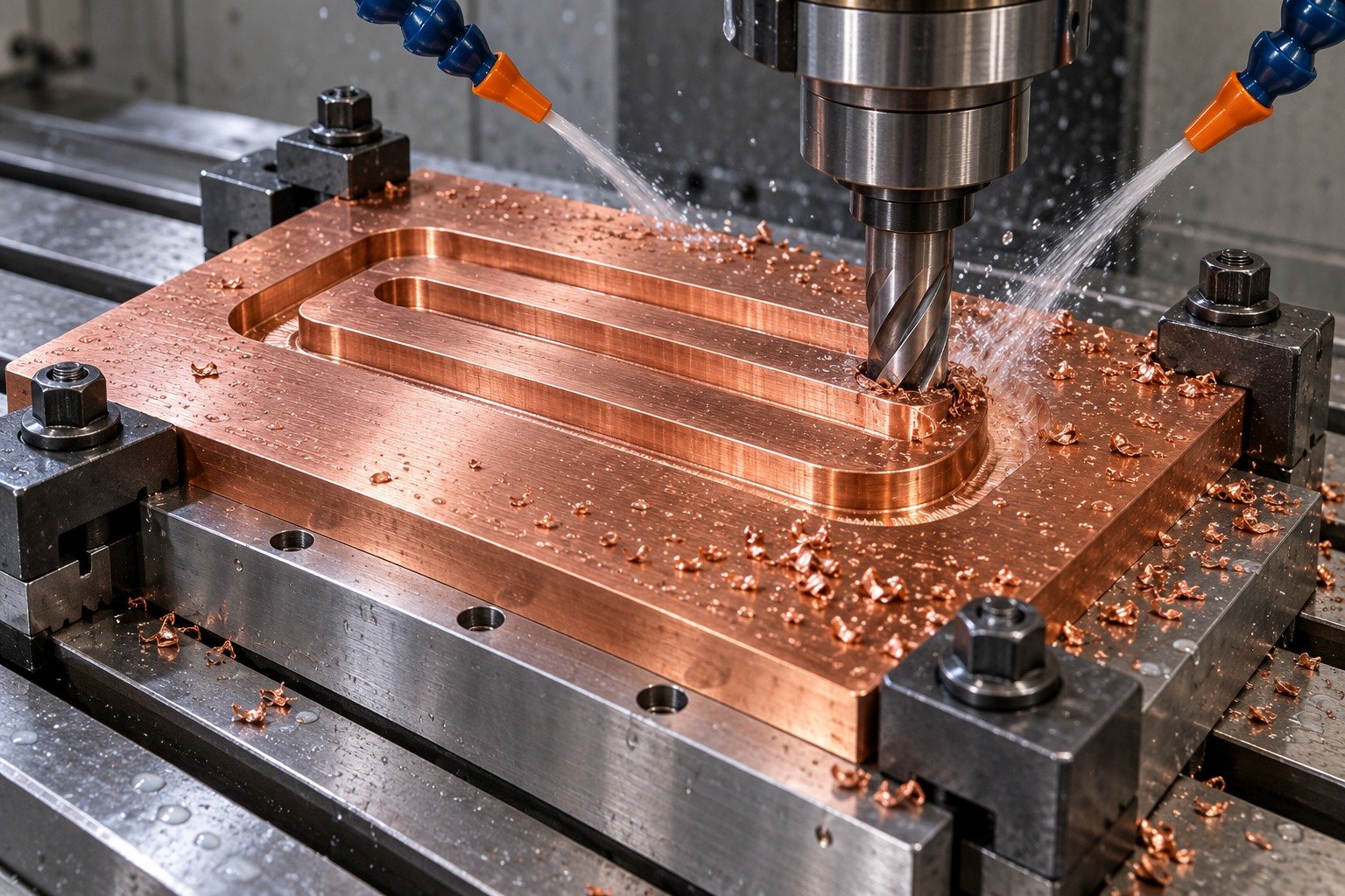
Plan channels and mating surfaces with stable support and an agreed finishing sequence.
Explore the Process →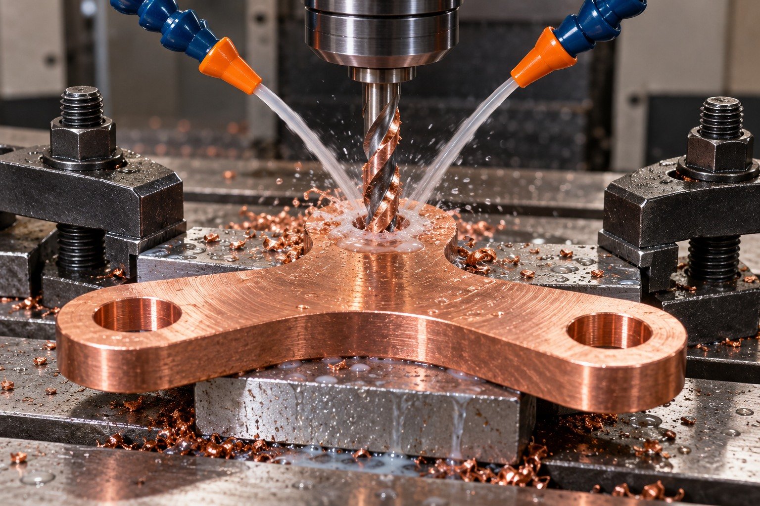
Define hole entry, thread standard, internal-edge access and gauge requirements.
Explore the Process →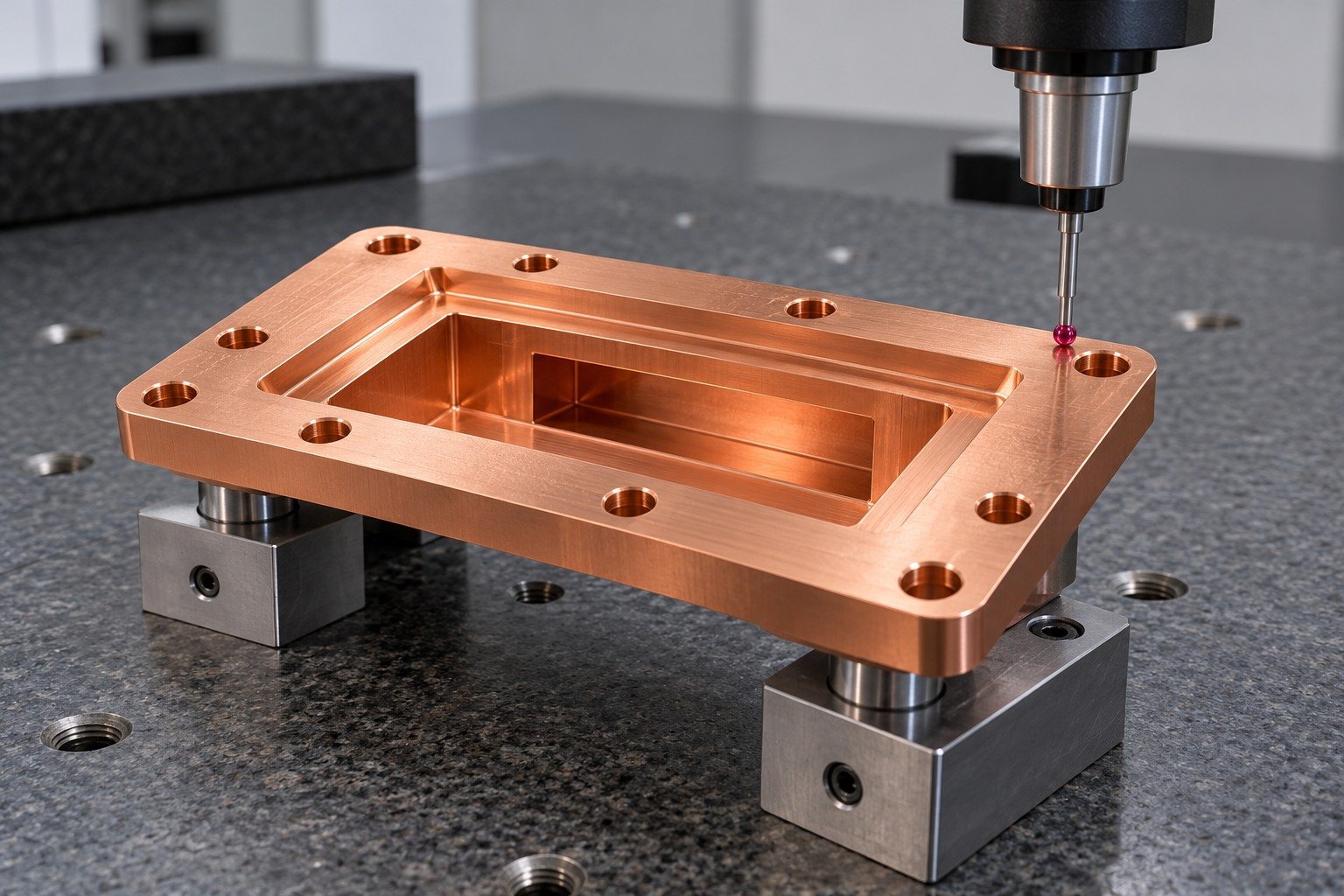
Verify the final flange, mounting and surface geometry against your drawing.
Explore the Process →Resolve these six drawing decisions before repeating the manufacturing route.
For C101 copper CNC machining, specify UNS C10100, product form and supplied condition. Review the original standard when a drawing says only C101; do not substitute a short name for the ordered grade.
Show the working feature and allowed edge condition.
Agree stock, support and final surface.
Inspect the actual finished state.
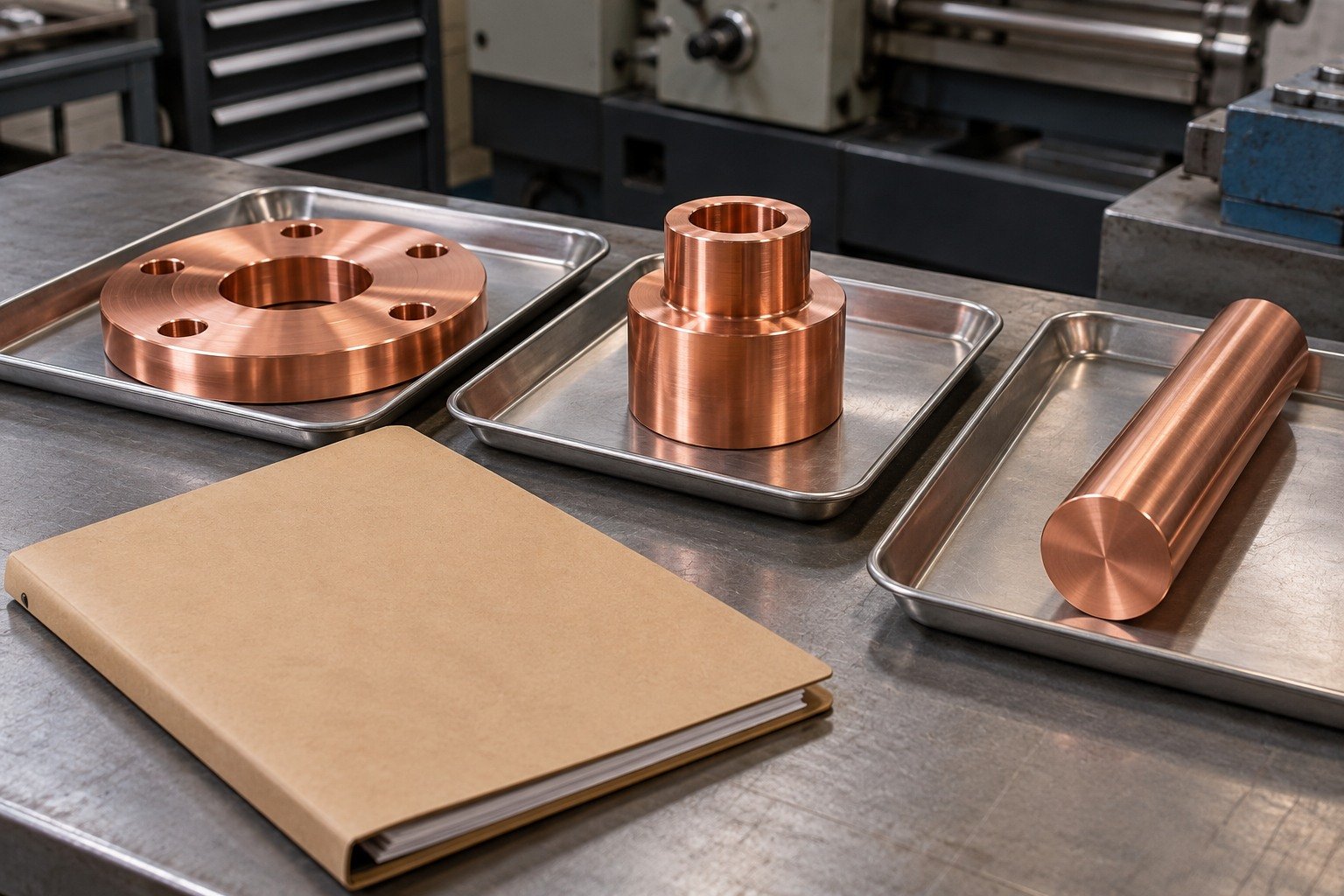
For C101 copper tapping and drilling, identify thread standard, run-out, intersecting holes and gauge access. Agree how hidden internal edges will be verified.
Show the working feature and allowed edge condition.
Agree stock, support and final surface.
Inspect the actual finished state.
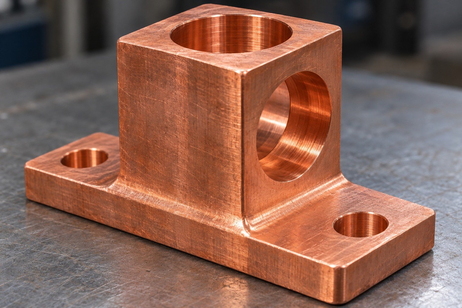
A material suitability reference does not qualify a joint or establish vacuum cleanliness. Specify joining responsibility, final state, cleaning acceptance and any separate testing before agreeing the route.
Show the working feature and allowed edge condition.
Agree stock, support and final surface.
Inspect the actual finished state.
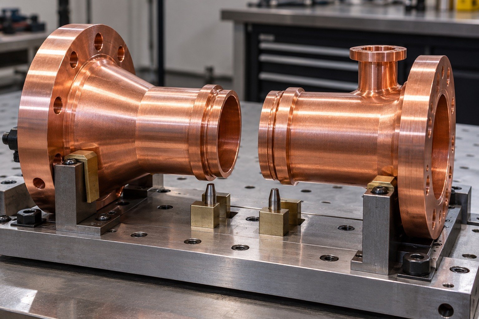
Show allowed edge breaks, channel corners and working lands that must retain their geometry. Agree first-sample acceptance for accessible and internal edges.
Show the working feature and allowed edge condition.
Agree stock, support and final surface.
Inspect the actual finished state.
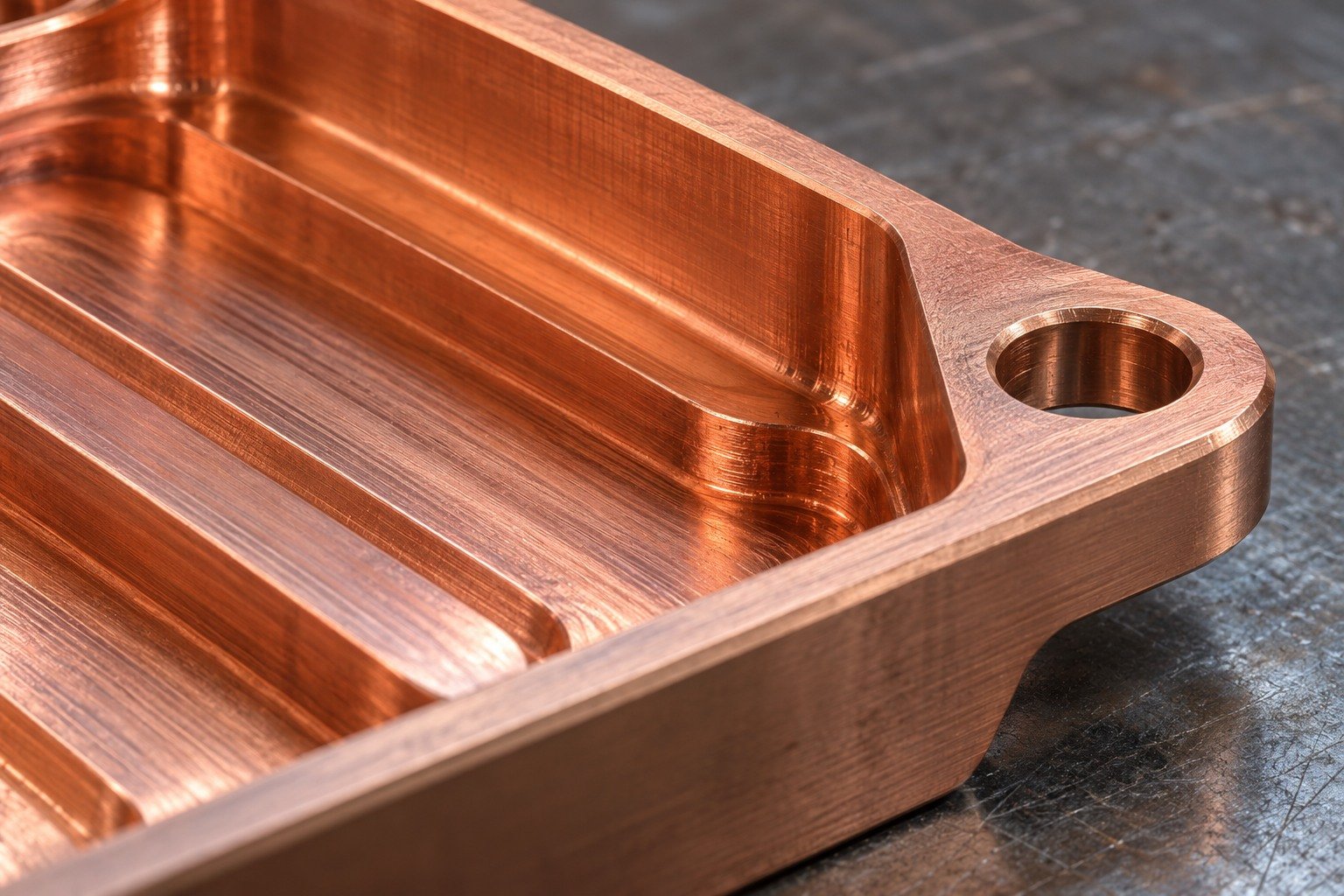
Specify roughness, flatness, cleaning, masking and handling protection on each functional land. A bright appearance does not establish RF, thermal, electrical or vacuum performance.
Show the working feature and allowed edge condition.
Agree stock, support and final surface.
Inspect the actual finished state.
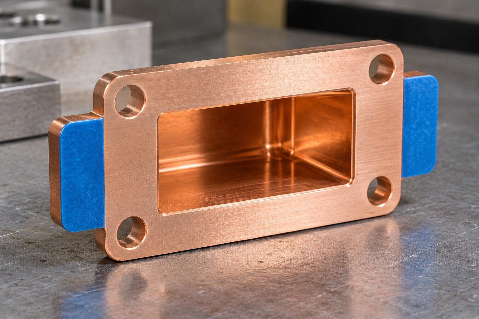
For your C101 copper precision machining review, link every critical dimension to final datums and measurement access. Copper softness makes clamping and support part of the dimensional review.
Show the working feature and allowed edge condition.
Agree stock, support and final surface.
Inspect the actual finished state.
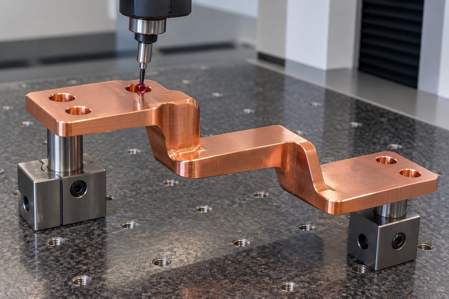
| Material review | Your approval input |
|---|---|
| C101 vs C102 copper | Specify UNS C10100 versus UNS C10200; compare complete chemistry, stock form and final requirement. |
| Old UK BS C101 | Normally Cu-ETP / CW004A; this is not the UNS C10100 OFE identity. |
| C110 / C145 / C172 | Keep ETP, tellurium and beryllium copper distinct; a similar appearance does not approve replacement. |
Confirm the actual standard system and obtain drawing-authority approval before changing material.
Compare Copper, Brass & Bronze →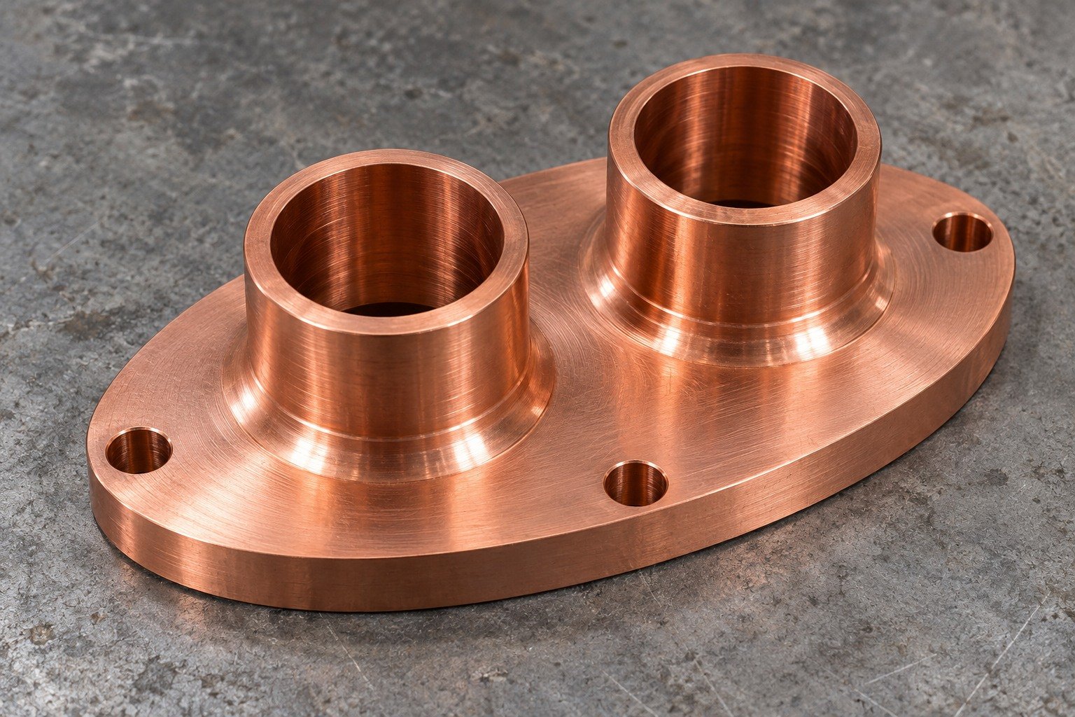
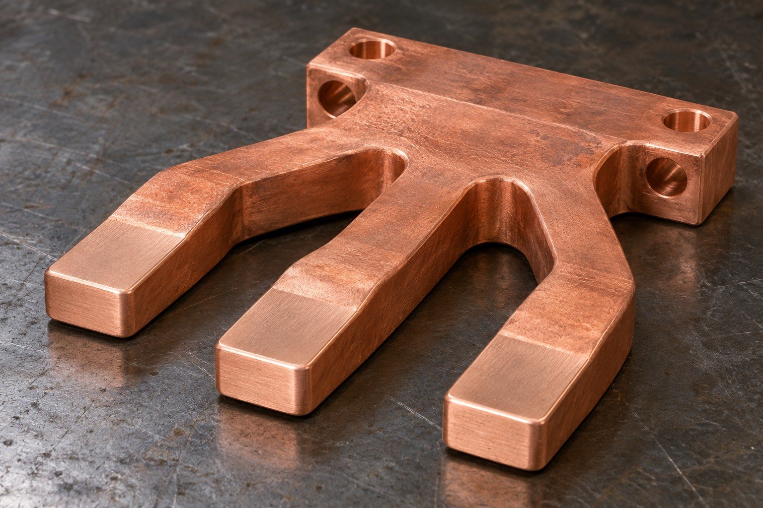
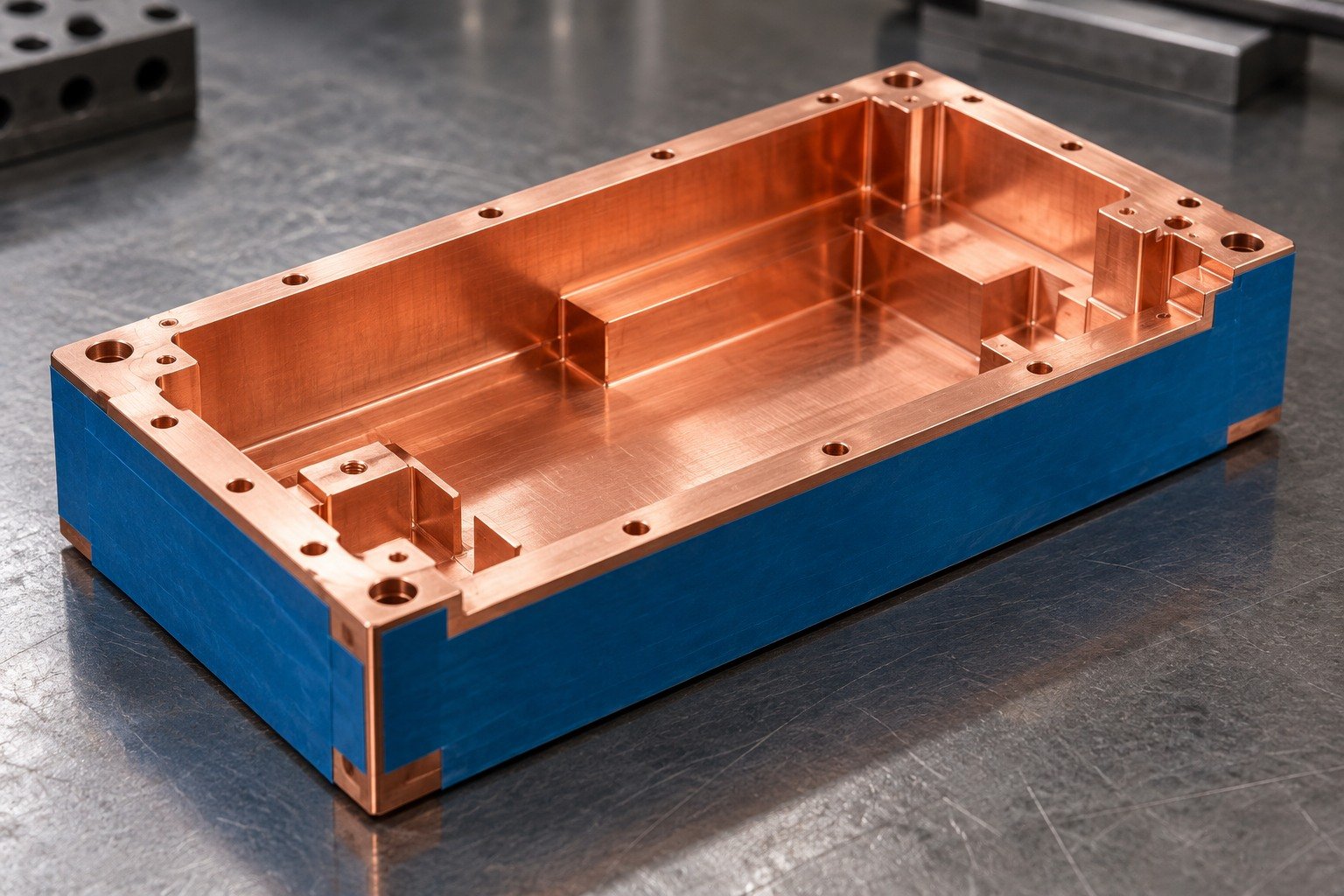
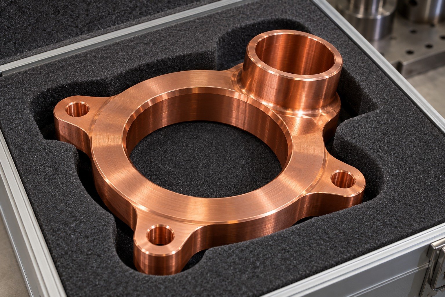
Illustrative appearances. State cleaning, accepted tool marks, masking and protection. Any plating needs a separate review of adhesion, thickness and final fit.
Surface Finishing →Grade, product form, temper and lot.
Contact features and accepted edges.
Final fit, surface and records.
For your custom C101 copper parts, agree product specification, supplied state, lot identity and document scope. Match incoming stock to the exact UNS designation.
Sampling and evidence scope are agreed with your quote.
Quality Assurance →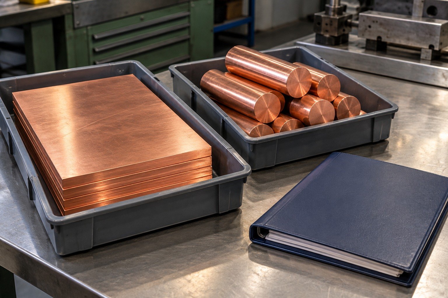
For C101 copper prototype machining, verify channels, mounting datums and accepted working surfaces on the complete first sample before repeat quantities.
Sampling and evidence scope are agreed with your quote.
Quality Assurance →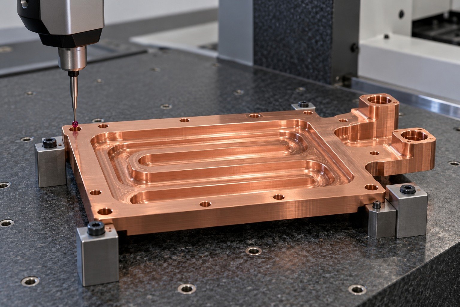
Inspect the final seal land, flange and mounting relationships. RF, pressure, leak, cleanliness or thermal tests require separate procedures and agreed acceptance scope.
Sampling and evidence scope are agreed with your quote.
Quality Assurance →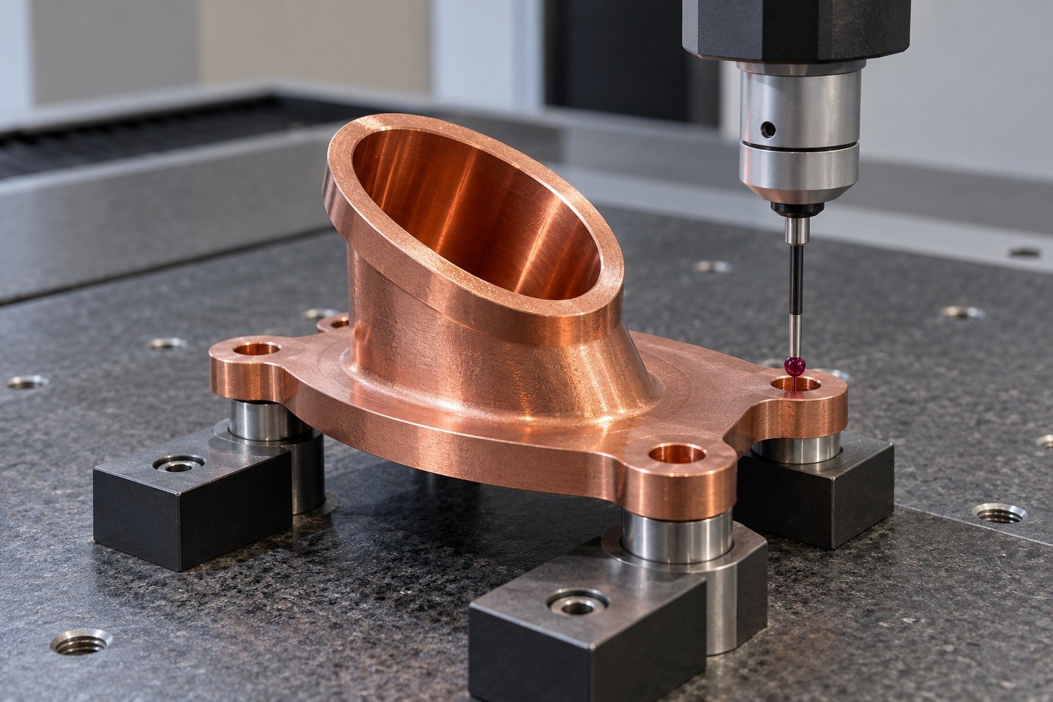
Agree individual separation, surface protection and lot identification. Your C101 copper parts manufacturer review should define the documents your receiving team actually needs.
Sampling and evidence scope are agreed with your quote.
Quality Assurance →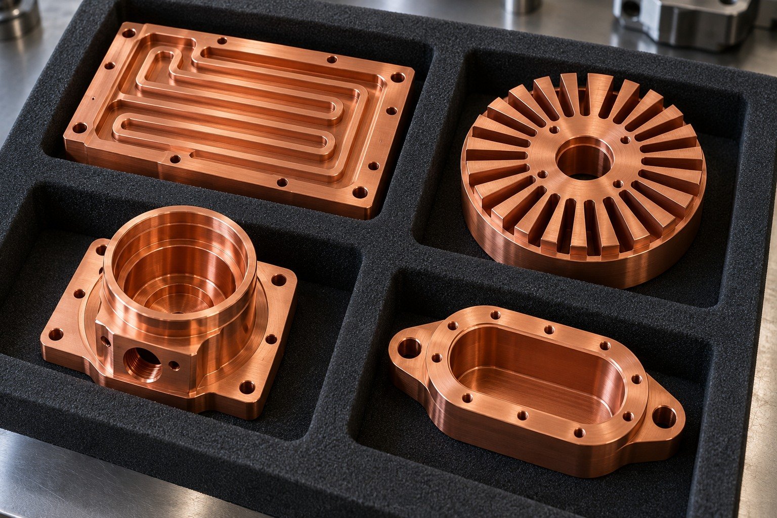
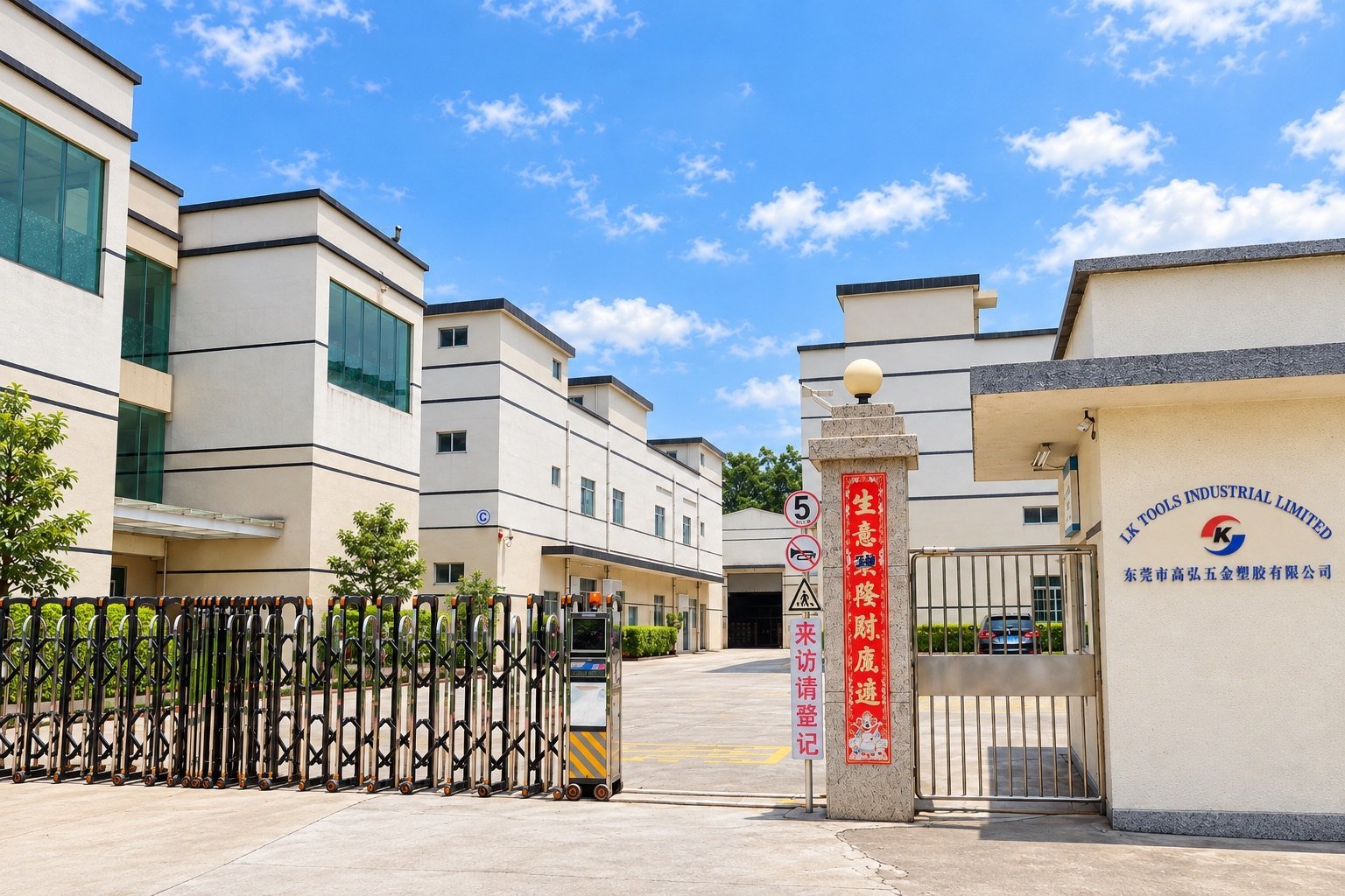
Connect China manufacturing with Dallas-area coordination for drawing review, sample decisions and delivery requirements.
If your specification means UNS C10100, it identifies oxygen-free electronic copper. Confirm the standard system: the short C101 name alone can refer to old UK tough-pitch copper instead.
Do not assume so. The Copper Information Center maps old BS C101 to Cu-ETP / CW004A, while UNS C10100 is the OFE reference associated with Cu-OFE / CW009A. Send the original material specification.
For C101 copper machinability, the selected bedra C10100 relative index is 20 with C36000 brass at 100. It is not a time ratio. Review chip control, sharp tool access, stock condition, support and accepted edges for the actual part.
Review the exact base grade, preparation, coating system, thickness, masking and final function with the finishing supplier. The material name alone does not qualify adhesion, vacuum compatibility or electrical performance.
Provide the critical dimensions, datums, wall geometry, stock state and final surface requirement. Your quotation confirms feature-specific acceptance after reviewing support and measurement access; no single tolerance is promised for every part.
Send CAD and a controlled drawing, UNS grade and product form, supplied state, trial and repeat quantities, working surfaces, accepted edges and inspection requirements. Keep any functional testing separate and explicit.
Confirm UNS C10100 versus UNS C10200 and compare complete material requirements. Selected conductivity minima and oxygen limits do not approve substitution or predict your complete assembly performance.
For C101 copper busbars, identify current path, contact lands and attachment geometry. For thermal parts, identify mounting and heat-transfer interfaces. Your C101 copper machining quote confirms the accepted drawing and manufacturing scope.