

Injection Molding
Tooling and molding for your repeat plastic parts.
From prototype to production, coordinated manufacturing solutions for your custom parts.
View All Services →
Precision parts for your tight tolerances and complex geometry.
Tooling and molding for your repeat plastic parts.

Metal casting options for your part and production volume.

Cutting, forming and welding for your fabricated parts.

Custom profiles for your section, length and finish requirements.

Finishes for your appearance, corrosion and wear requirements.

Sub-assemblies and final builds for your production program.

Production tooling built around your process and volume.

Prototype parts to check fit, function and design.
DFM, process planning and production support for your project.
Inspection, documentation, inventory and delivery planning for your program.
Choose air- or liquid-cooling components around your thermal and mechanical requirements.

Manufacturing support for your cold plates, manifolds and cooling assemblies.

Find components for your power electronics, energy, laser and telecom application.

Components for your electronic systems.
Start with your functional and quality requirements.
Build around your operating environment.
From prototype to production, review material performance, manufacturability and cost for your part.
Review grade, temper and finish for your metal parts.
 AluminumStrength, weight and machining›
 Stainless SteelCorrosion and finish requirements›
 Carbon & Alloy SteelDiscuss grade and heat treatment›
 Tool SteelDiscuss tooling and wear needs›
 TitaniumReview grade and part geometry›
 Copper & BrassDiscuss conductivity and machining›
Match your polymer to function, process and environment.
 ABSReview enclosure and molding needs›
 Polycarbonate (PC)Discuss clarity and impact needs›
 Nylon (PA)Review moisture and wear conditions›
 POM / AcetalReview fit and sliding features›
 PEEKDiscuss operating conditions›
 PTFEReview friction and chemical exposure›
 ULTEM / PEIDiscuss thermal and electrical needs›
Confirm grade availability and application requirements.
 Silicone / LSRDiscuss flexible component needs›
 TPU / TPEReview flexibility and processing›
 EPDMReview weathering and chemical exposure.›
 NBRReview oil and fuel exposure.›
 FKMReview temperature and chemical exposure.›
 G10 / FR4Review insulation and laminate needs›
 CompositesReview stiffness, weight and laminate.›Customer-Specified MaterialsConfirm your grade and requirements.›Other Specialty MaterialsDiscuss your application and grade.›
Practical guidance for your part geometry and material decisions.
Prepare your process, budget and sourcing questions.
Build your knowledge before production.
Learn who we are and how we operate.
Find our U.S. support team or start a conversation.

For your A2 tool steel machining services inquiry, connect the supplied condition to your die profile, punch fit or wear surface. Define heat-treatment responsibility and final finishing before production.
A2 cold work tool steel is used for industrial tooling where the complete material and processing route matter. Treat A2 tool steel properties as condition-dependent, not one universal hardness or service-life promise.
Cold-work tool steel. For European sourcing, review 1.2363 / X100CrMoV5 and the actual product specification.
Annealed A2 tool steel for initial machining and hardened A2 tool steel for the working condition require different planning.
A comparison name supports review; it does not approve a substitute.
| Element | K305 producer average wt.% |
|---|---|
| C | 1.00 |
| Si | 0.30 |
| Mn | 0.55 |
| Cr | 5.20 |
| Mo | 1.10 |
| V | 0.25 |
BÖHLER K305 average analysis. Producer data refer to long products. Confirm your supplied product form and material record; these are not acceptance ranges.
| Stage | Your required decision |
|---|---|
| Incoming stock | Product form, actual condition and grade identity. |
| Specified treatment | Target condition, responsible party and required evidence. |
| Finished tooling | Final datums, working features and inspection after finishing. |
The specified thermal route must suit your actual section and geometry.
Selected producer averages · wt.% · common axis 0–12%
Composition only. These bars are not a wear, toughness, machinability or corrosion score. They are not test results from your material lot.
Select the part you need, then review machining, condition and final acceptance.
Your A2 tool steel dies need a supported working profile, clear datum faces and a defined mating tool. For custom A2 tool steel parts, show the complete assembly relationship.
| Your decision | What to define |
|---|---|
| Your fit | Working profile, die backing and locating bores. |
| Your process | Initial machining, specified treatment and final finishing. |
| Your approval | Controlled drawing, final condition and receiving evidence. |

A2 tool steel CNC machining must leave access for profile finishing and datum recovery. Define pocket radii and the accepted final edge.
| Your decision | What to define |
|---|---|
| Your fit | Working profile, die backing and locating bores. |
| Your process | Initial machining, specified treatment and final finishing. |
| Your approval | Controlled drawing, final condition and receiving evidence. |
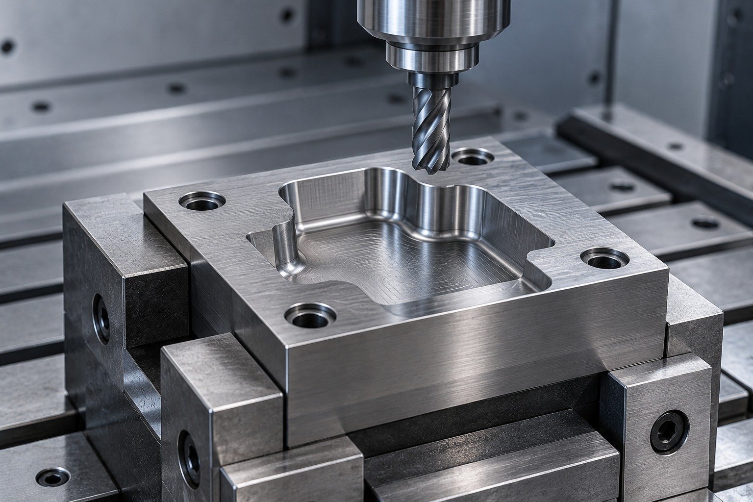
Confirm the required treatment after initial machining. Keep finish stock on features that must be corrected after dimensional movement.
| Your decision | What to define |
|---|---|
| Your fit | Working profile, die backing and locating bores. |
| Your process | Initial machining, specified treatment and final finishing. |
| Your approval | Controlled drawing, final condition and receiving evidence. |

Inspect the working profile and locating bores from the final datum scheme. Agree the material record and drawing revision.
| Your decision | What to define |
|---|---|
| Your fit | Working profile, die backing and locating bores. |
| Your process | Initial machining, specified treatment and final finishing. |
| Your approval | Controlled drawing, final condition and receiving evidence. |
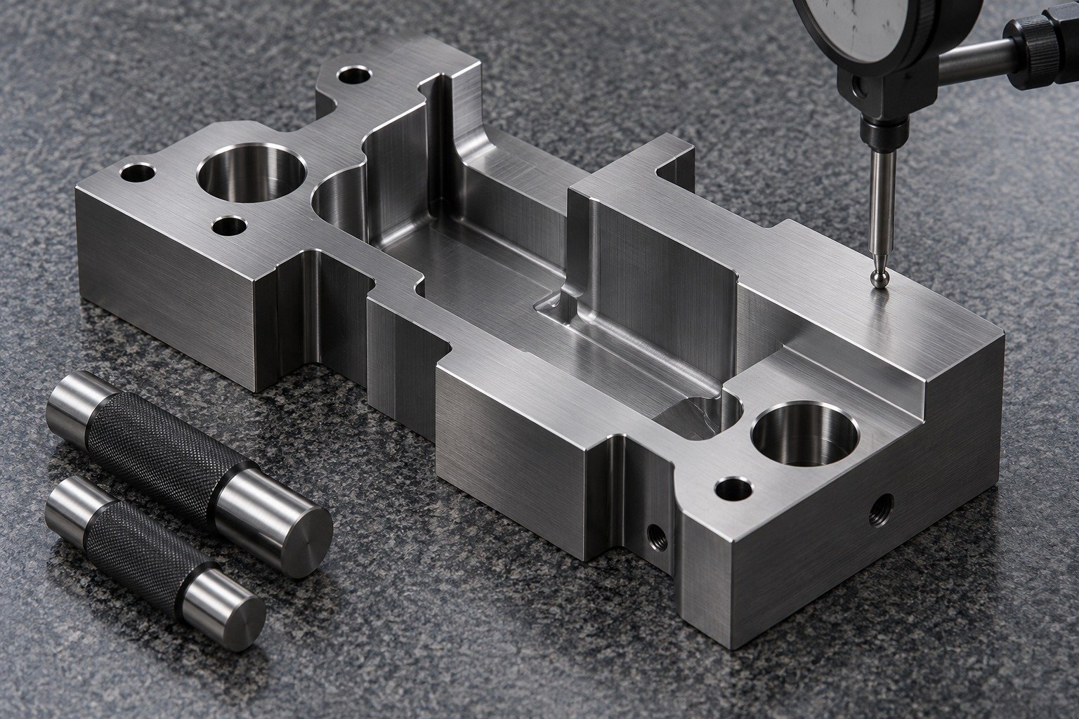
For your A2 tool steel punches, connect the working end to the supported shank, shoulder radius and locating diameter. Define the mating die and the material being worked.
| Your decision | What to define |
|---|---|
| Your fit | Working end, supported length and shoulder position. |
| Your process | Initial machining, specified treatment and final finishing. |
| Your approval | Controlled drawing, final condition and receiving evidence. |
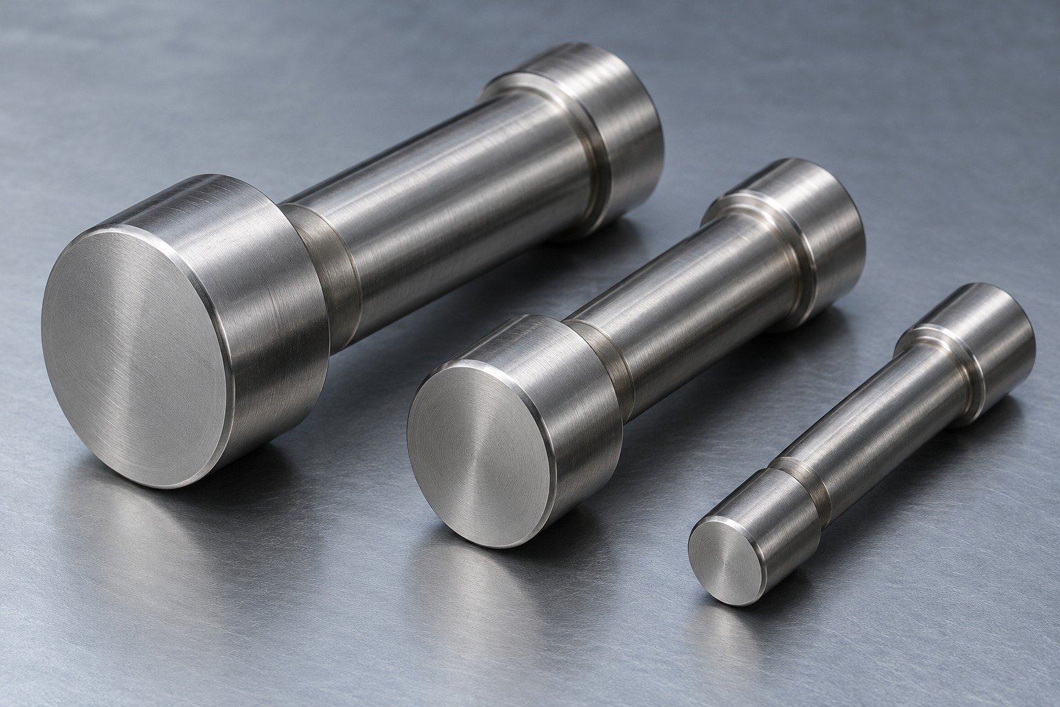
For A2 tool steel turning, identify gripping allowance and diameter relationships. Keep cross-features and reliefs reachable.
| Your decision | What to define |
|---|---|
| Your fit | Working end, supported length and shoulder position. |
| Your process | Initial machining, specified treatment and final finishing. |
| Your approval | Controlled drawing, final condition and receiving evidence. |
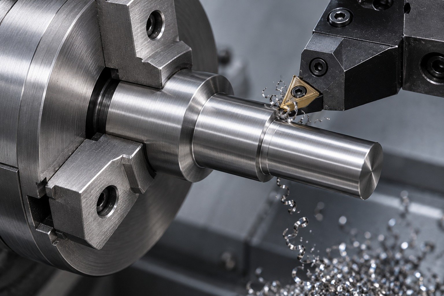
Relate final punch diameter and straightness to the specified working condition. Agree when the locating land reaches final size.
| Your decision | What to define |
|---|---|
| Your fit | Working end, supported length and shoulder position. |
| Your process | Initial machining, specified treatment and final finishing. |
| Your approval | Controlled drawing, final condition and receiving evidence. |
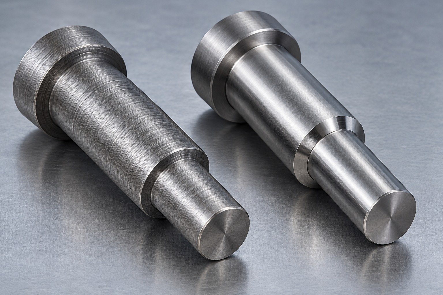
Define how working diameter, shoulder position and concentric relationships are checked after the full route.
| Your decision | What to define |
|---|---|
| Your fit | Working end, supported length and shoulder position. |
| Your process | Initial machining, specified treatment and final finishing. |
| Your approval | Controlled drawing, final condition and receiving evidence. |
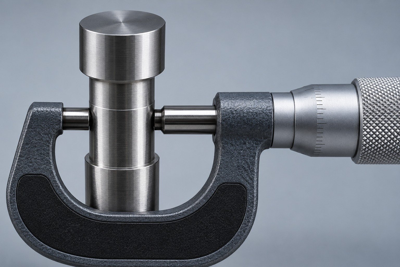
For your A2 tool steel wear plates, state the contact pair, sliding direction, mounting layout and exposure. A grade name alone does not define wear performance.
| Your decision | What to define |
|---|---|
| Your fit | Contact face, mounting counterbores and mating rail. |
| Your process | Initial machining, specified treatment and final finishing. |
| Your approval | Controlled drawing, final condition and receiving evidence. |

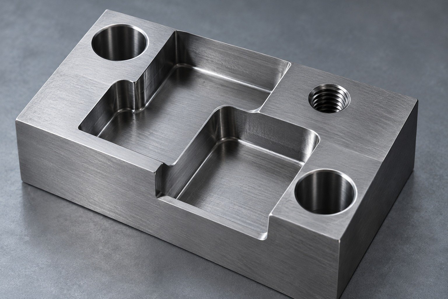
For A2 tool steel milling, review thin relieved sections, counterbores and clamping faces. Identify the surface that controls final thickness.
| Your decision | What to define |
|---|---|
| Your fit | Contact face, mounting counterbores and mating rail. |
| Your process | Initial machining, specified treatment and final finishing. |
| Your approval | Controlled drawing, final condition and receiving evidence. |

Review asymmetric stock removal and the thermal route before final grinding. Keep sufficient material for the agreed finished state.
| Your decision | What to define |
|---|---|
| Your fit | Contact face, mounting counterbores and mating rail. |
| Your process | Initial machining, specified treatment and final finishing. |
| Your approval | Controlled drawing, final condition and receiving evidence. |
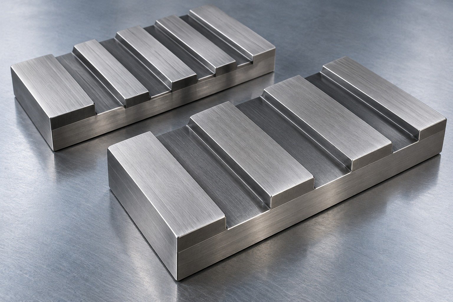
Measure final thickness, mounting relationships and contact-face geometry. Define handling protection for ground surfaces.
| Your decision | What to define |
|---|---|
| Your fit | Contact face, mounting counterbores and mating rail. |
| Your process | Initial machining, specified treatment and final finishing. |
| Your approval | Controlled drawing, final condition and receiving evidence. |
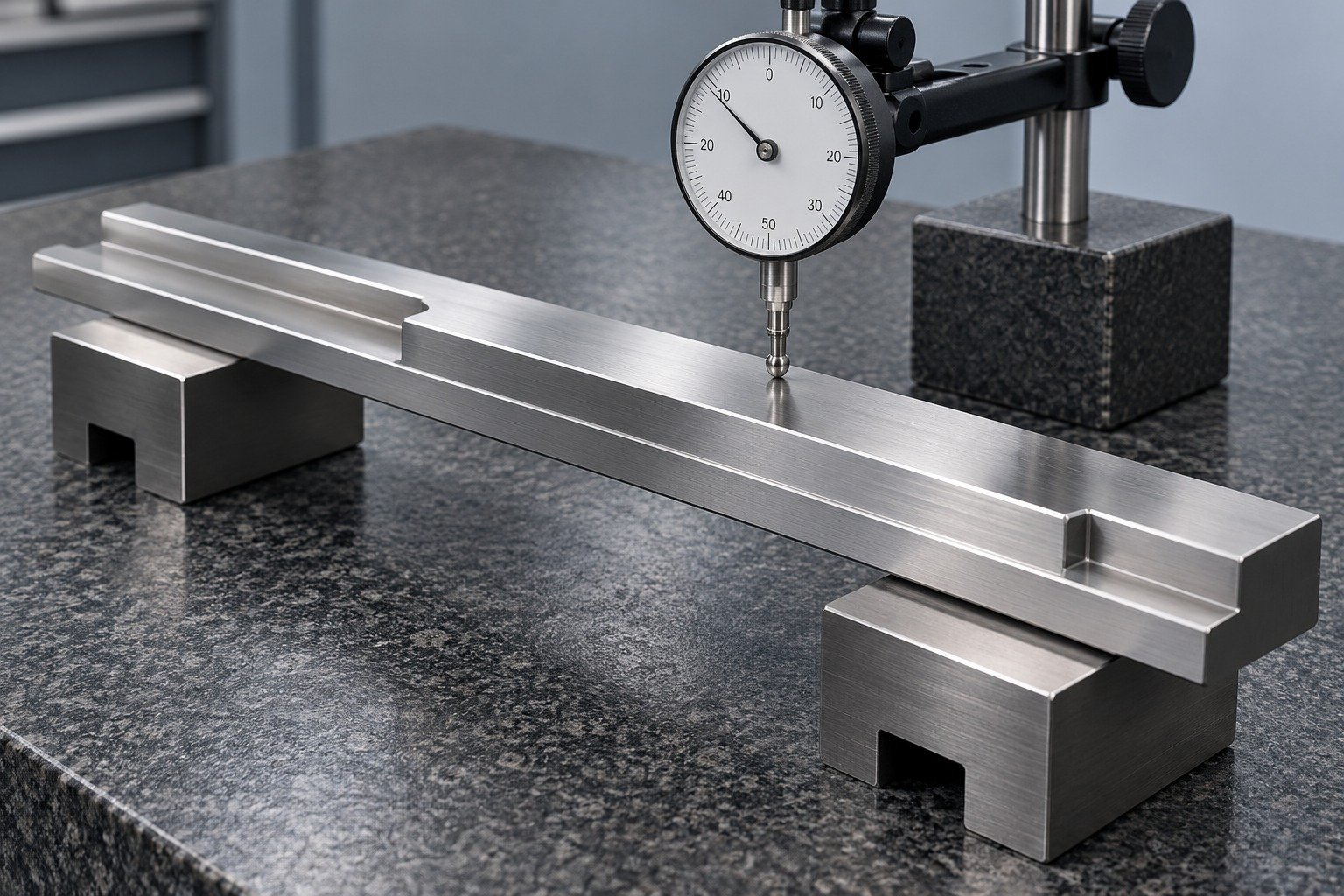
For an A2 gauge or locating fixture, identify reference faces, locating fits and the measurement environment. Specify the calibration or verification scope your receiving team needs.
| Your decision | What to define |
|---|---|
| Your fit | Reference planes, locating diameter and gauge function. |
| Your process | Initial machining, specified treatment and final finishing. |
| Your approval | Controlled drawing, final condition and receiving evidence. |
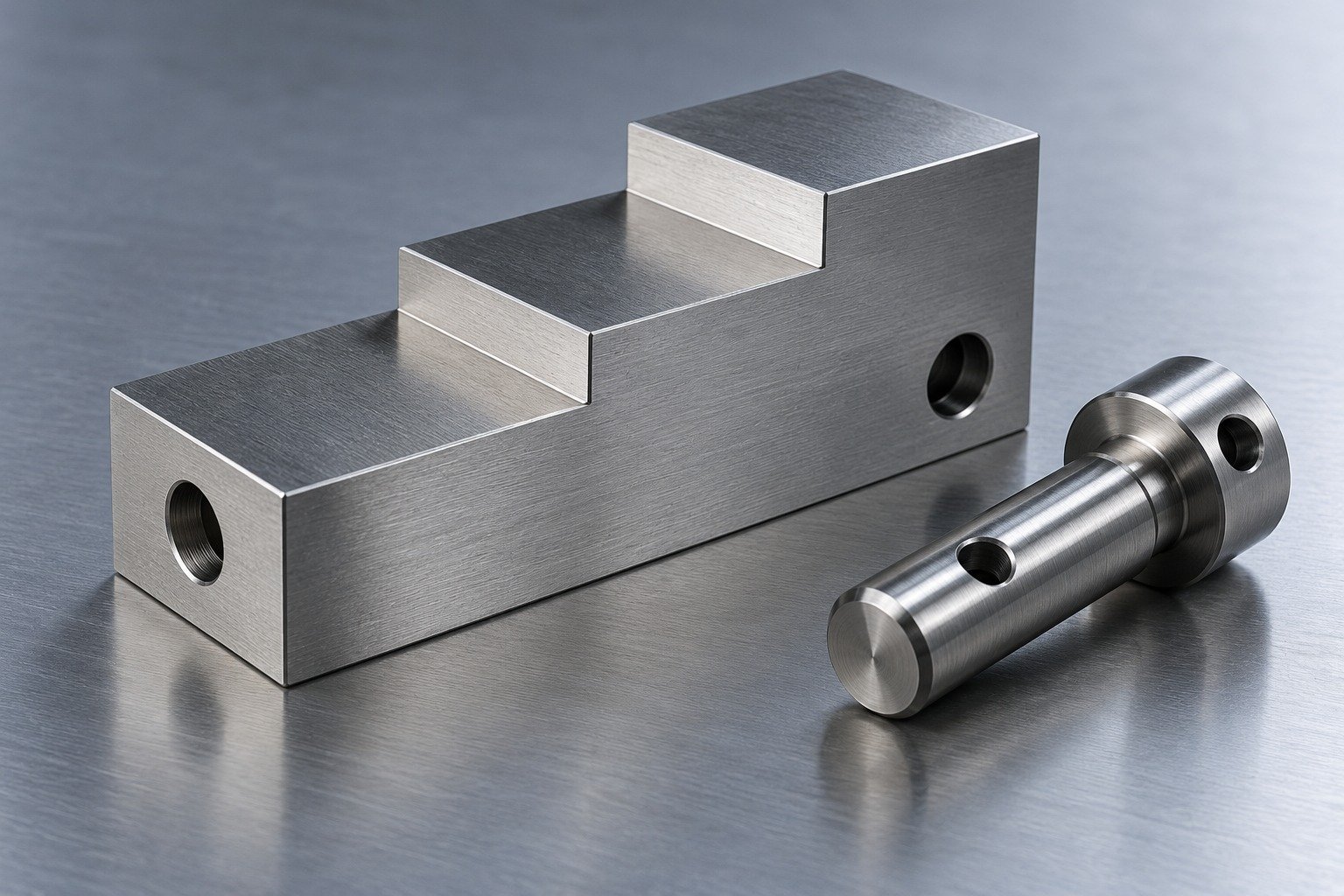
Machine reliefs and accessible features around the controlled datums. Confirm which surfaces need later grinding or profile finishing.
| Your decision | What to define |
|---|---|
| Your fit | Reference planes, locating diameter and gauge function. |
| Your process | Initial machining, specified treatment and final finishing. |
| Your approval | Controlled drawing, final condition and receiving evidence. |
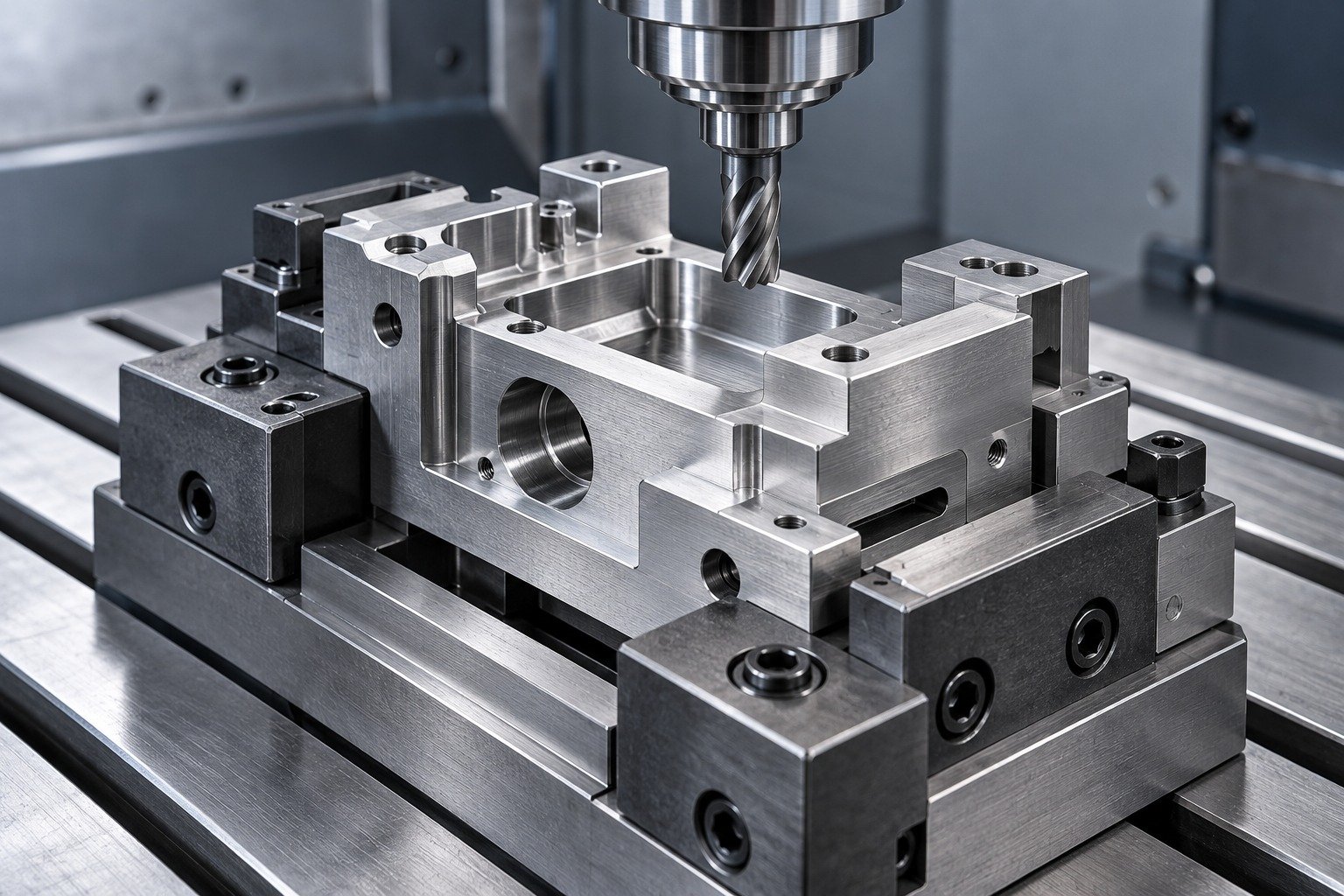
Define the working condition and sequence before closing critical fits. Keep roughing and final acceptance as separate stages.
| Your decision | What to define |
|---|---|
| Your fit | Reference planes, locating diameter and gauge function. |
| Your process | Initial machining, specified treatment and final finishing. |
| Your approval | Controlled drawing, final condition and receiving evidence. |
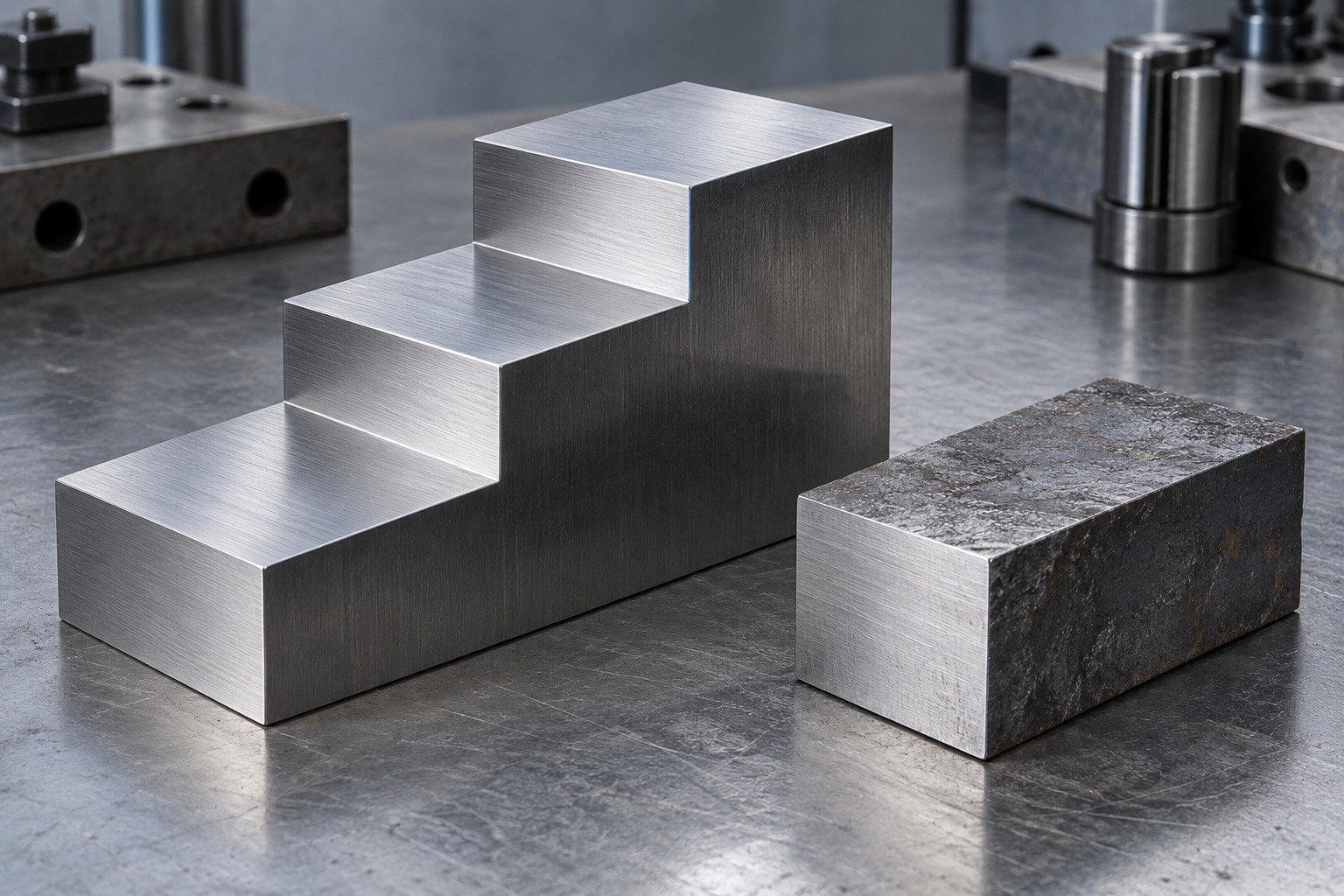
Agree the final inspection method, reference scheme and records. Do not assume a machined fixture is a calibrated gauge.
| Your decision | What to define |
|---|---|
| Your fit | Reference planes, locating diameter and gauge function. |
| Your process | Initial machining, specified treatment and final finishing. |
| Your approval | Controlled drawing, final condition and receiving evidence. |

A2 tool steel machinability depends on the actual condition, geometry and operation. Agree the route for your drawing; a generic cutting-speed table is not a production plan.
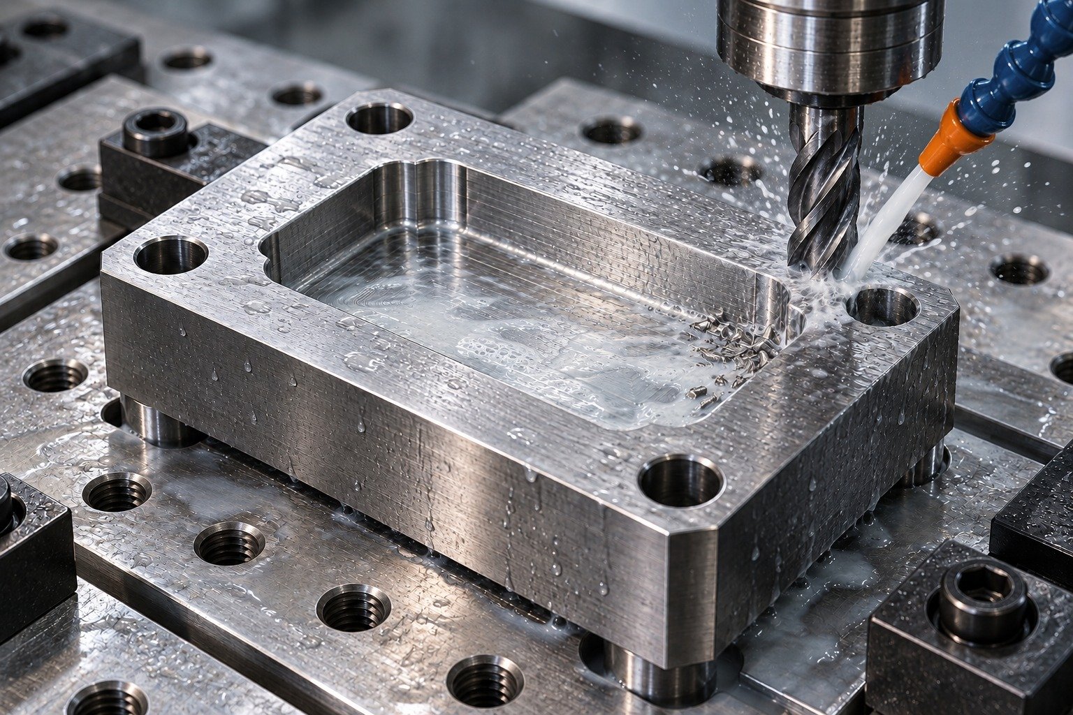
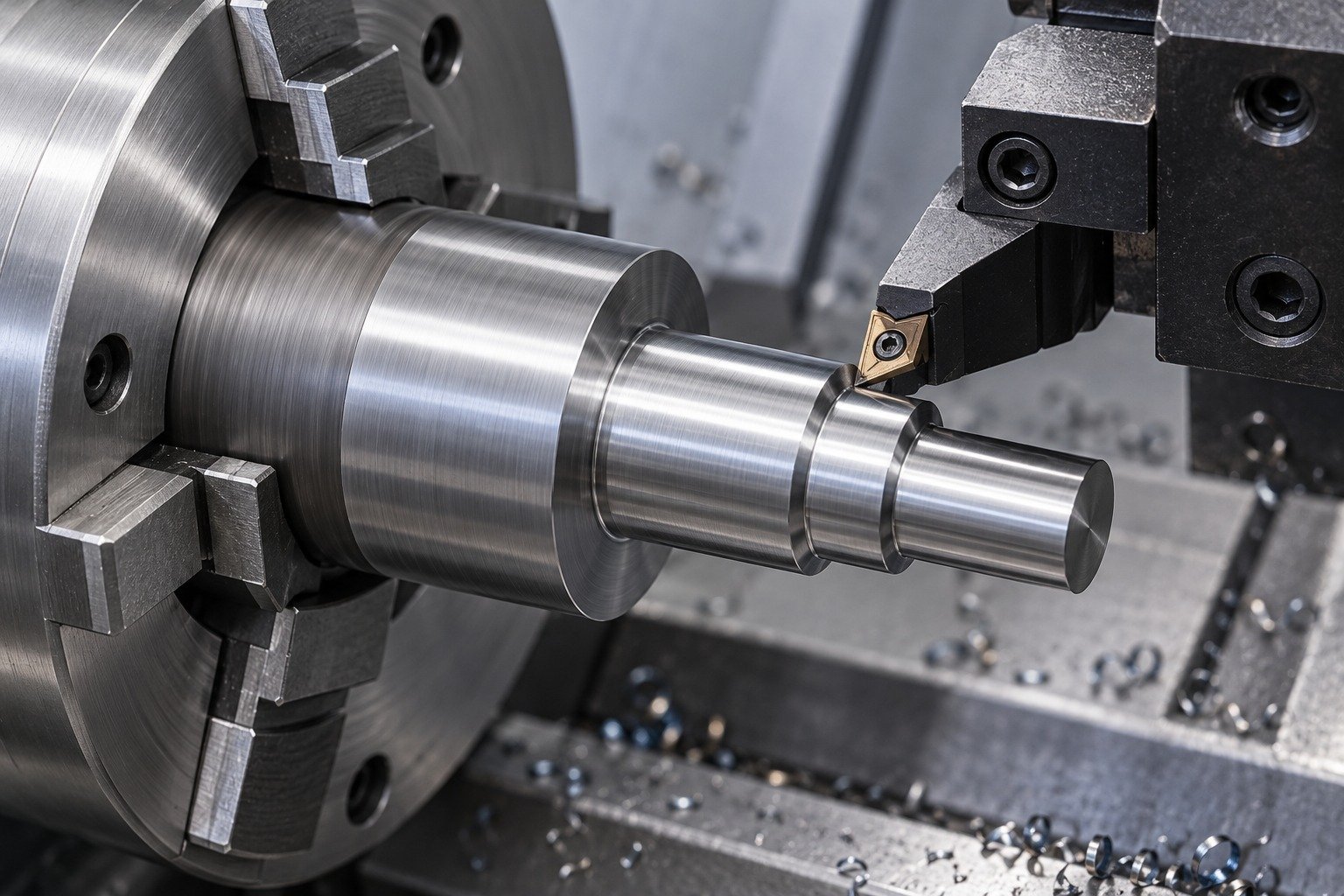

Define A2 tool steel grinding allowance and final measurement state.
Explore Precision Grinding →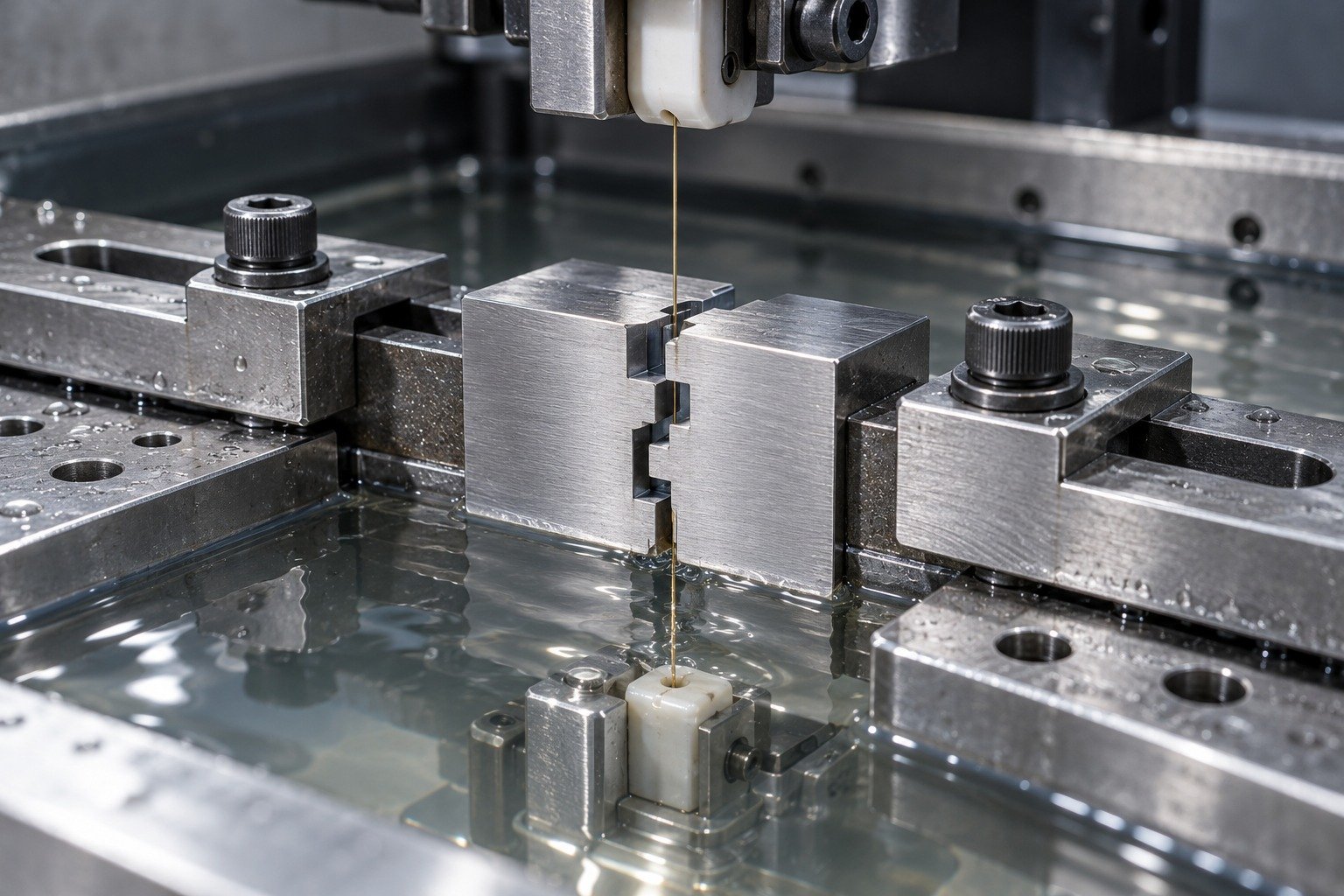
For A2 tool steel wire EDM review, identify through profiles and final surface requirements.
Explore Wire EDM →Connect A2 tool steel heat treatment to finishing and inspection before approving the first production route.
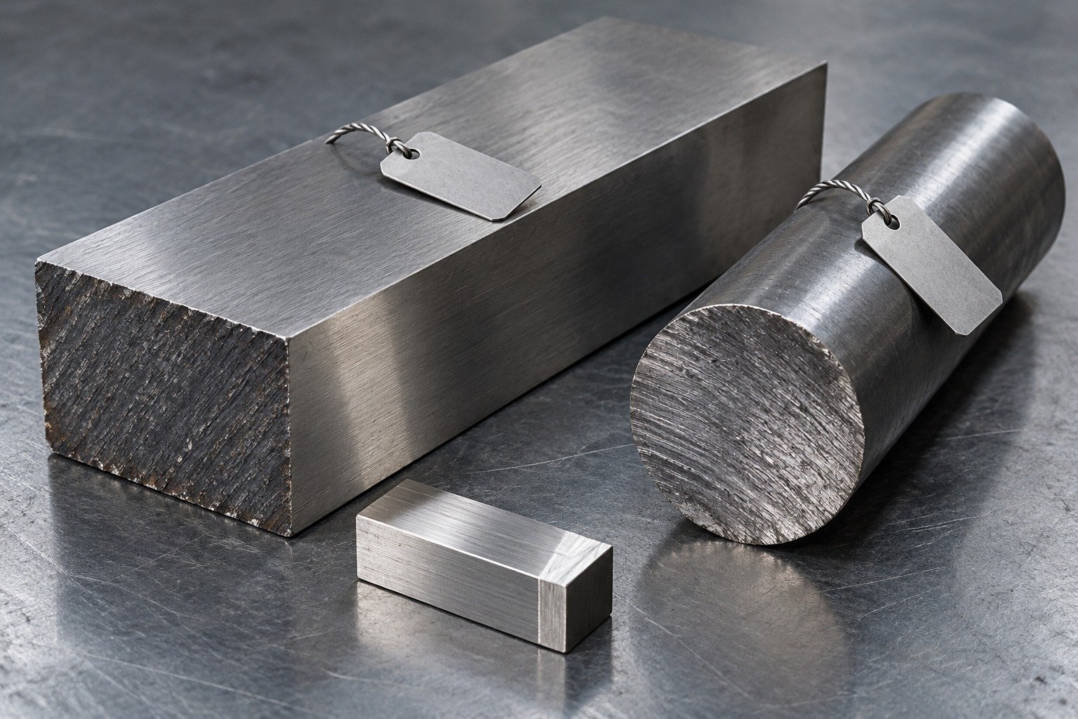
Check the full designation, product form, supplied state and lot record. Unknown scrap or a similar trade name does not establish AISI A2.
Show the controlled feature and final state.
Agree remaining stock for the actual route.
Verify the finished fit and specified condition.
Show useful thread engagement, bore intersections and burr access. Identify which locating features are sized after treatment.
Show the controlled feature and final state.
Agree remaining stock for the actual route.
Verify the finished fit and specified condition.
Air hardening does not mean zero movement. Agree section changes, finish stock, datum recovery and the point at which the final dimensions are accepted.
Show the controlled feature and final state.
Agree remaining stock for the actual route.
Verify the finished fit and specified condition.

Identify permitted corner radii and edge breaks, backing section and the expected load direction. Avoid treating maximum hardness as the only design target.
Show the controlled feature and final state.
Agree remaining stock for the actual route.
Verify the finished fit and specified condition.
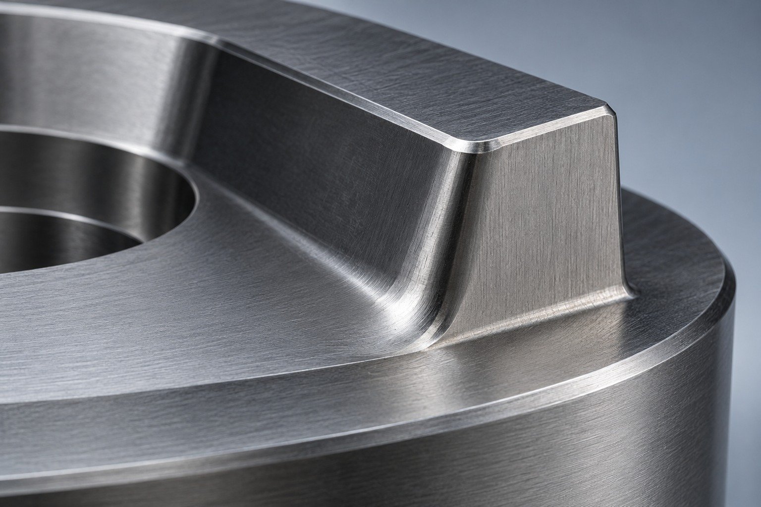
Define the finish system, masked working faces and locating bores. Review its compatibility with your specified A2 condition and acceptance requirements.
Show the controlled feature and final state.
Agree remaining stock for the actual route.
Verify the finished fit and specified condition.
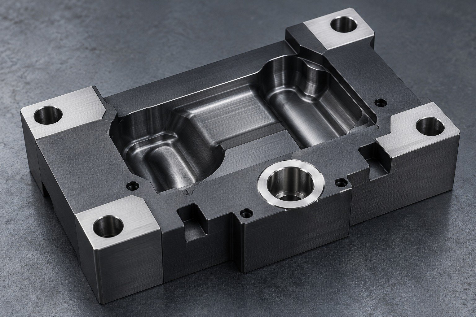
For A2 tool steel machining tolerances, identify each critical feature, datum and measurement state. Agree dimensional and hardness evidence separately.
Show the controlled feature and final state.
Agree remaining stock for the actual route.
Verify the finished fit and specified condition.
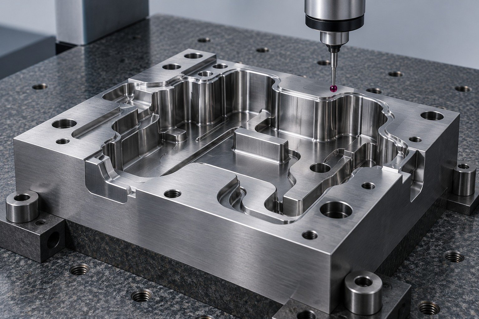

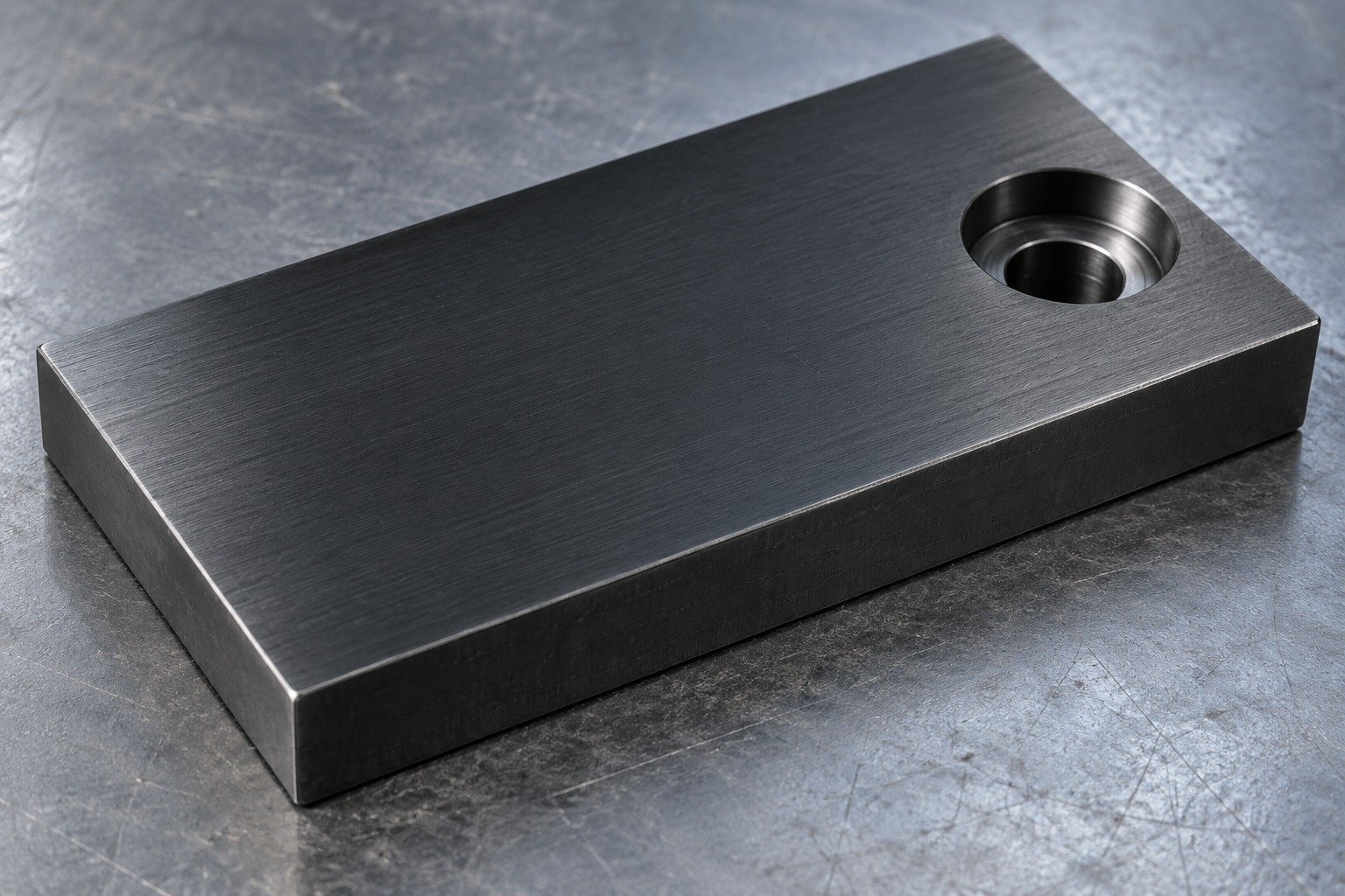
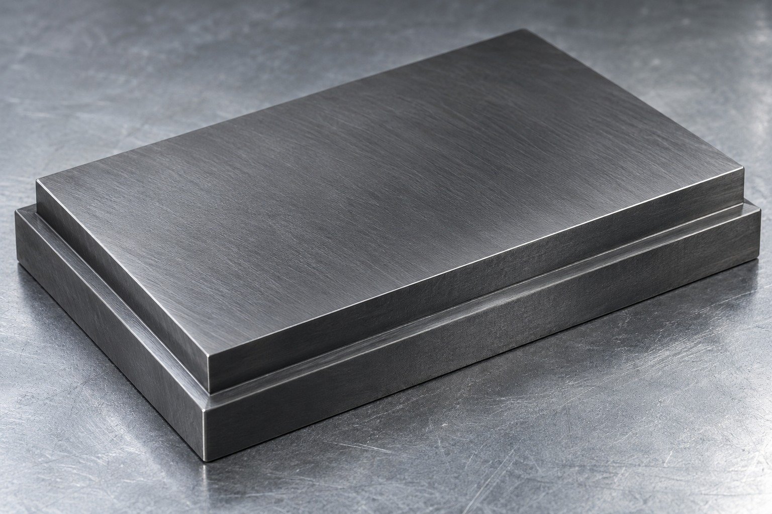
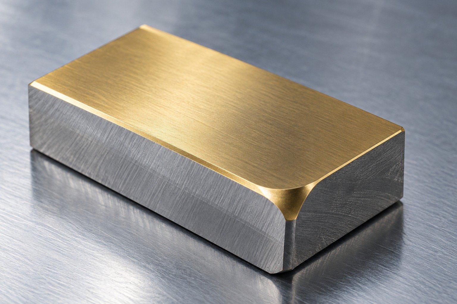
Illustrative appearance samples. Protection, treatment compatibility, masking and manufacturing scope require project review. A visual sample is not a process specification.
Surface Finishing →| Compare | What your drawing must resolve |
|---|---|
| A2 vs D2 tool steel | Abrasive wear, impact, working-edge support and the finishing route. |
| A2 vs O1 tool steel | Required properties, actual hardening route, section and final geometry. |
| European comparison | 1.2363 / X100CrMoV5 is a review reference; confirm the product standard and supplied state. |
Confirm an alternative before purchase. Do not assume that similar names or higher alloy content approve a replacement.
Identity, stock form and supplied condition.
Working condition and remaining finish stock.
Functional features, protection and records.
Confirm A2 identity, supplied condition, stock dimensions and required lot evidence before machining.
Sampling and document scope are agreed with your quotation.
Quality Assurance →
Review the sample from initial datums through specified treatment, remaining finish stock and the intended final inspection.
Sampling and document scope are agreed with your quotation.
Quality Assurance →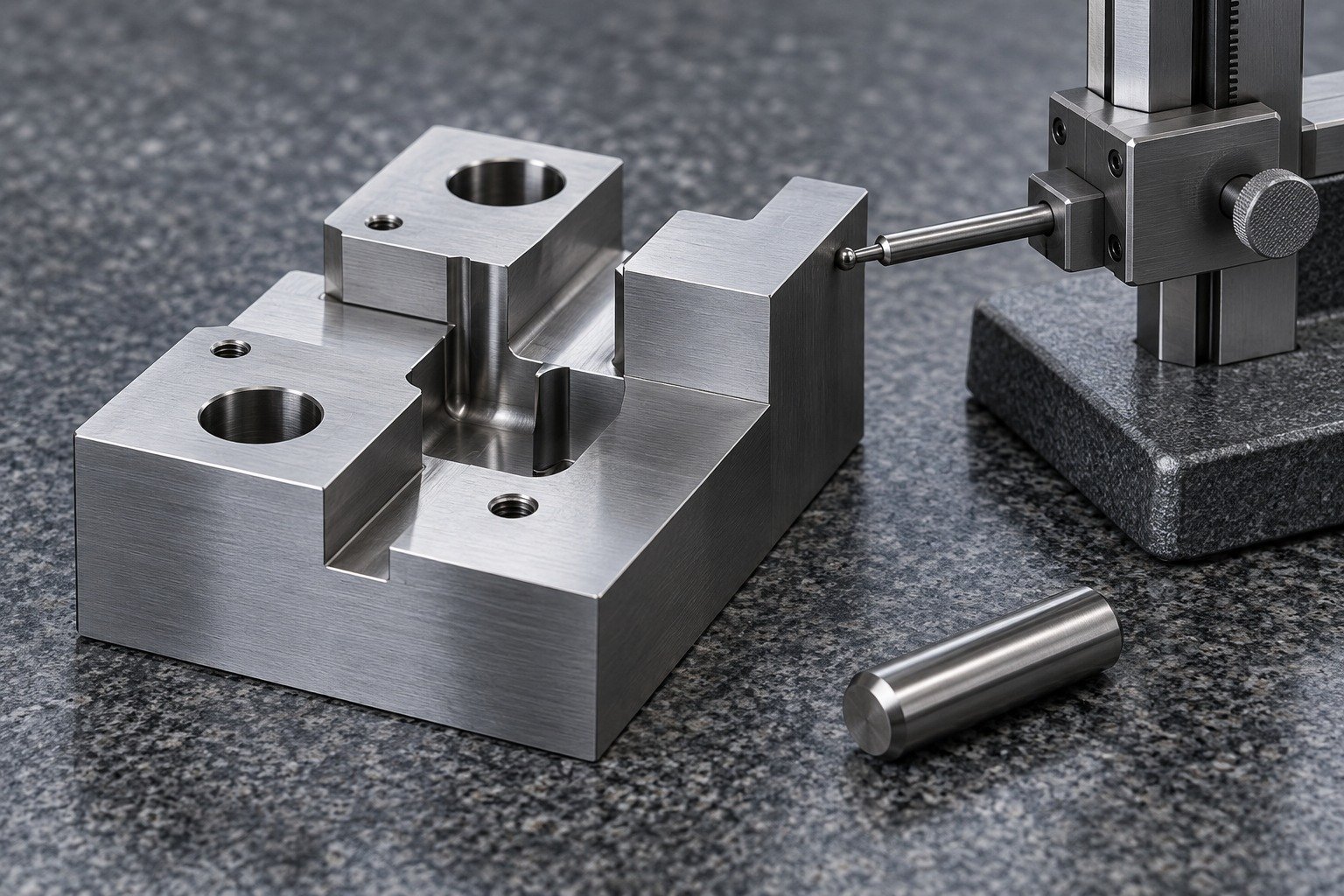
Agree methods for the final profile, thickness, locating bores or punch diameters. Specify hardness test locations and acceptance where required.
Sampling and document scope are agreed with your quotation.
Quality Assurance →
Define protected edges, identification, packaging and the material or inspection records your receiving team needs.
Sampling and document scope are agreed with your quotation.
Quality Assurance →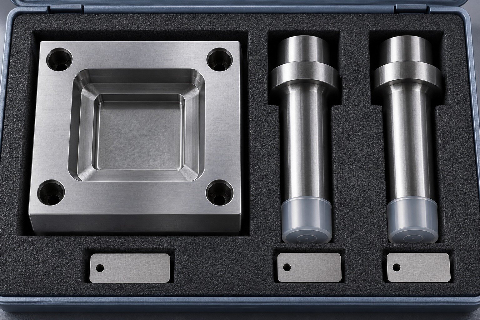
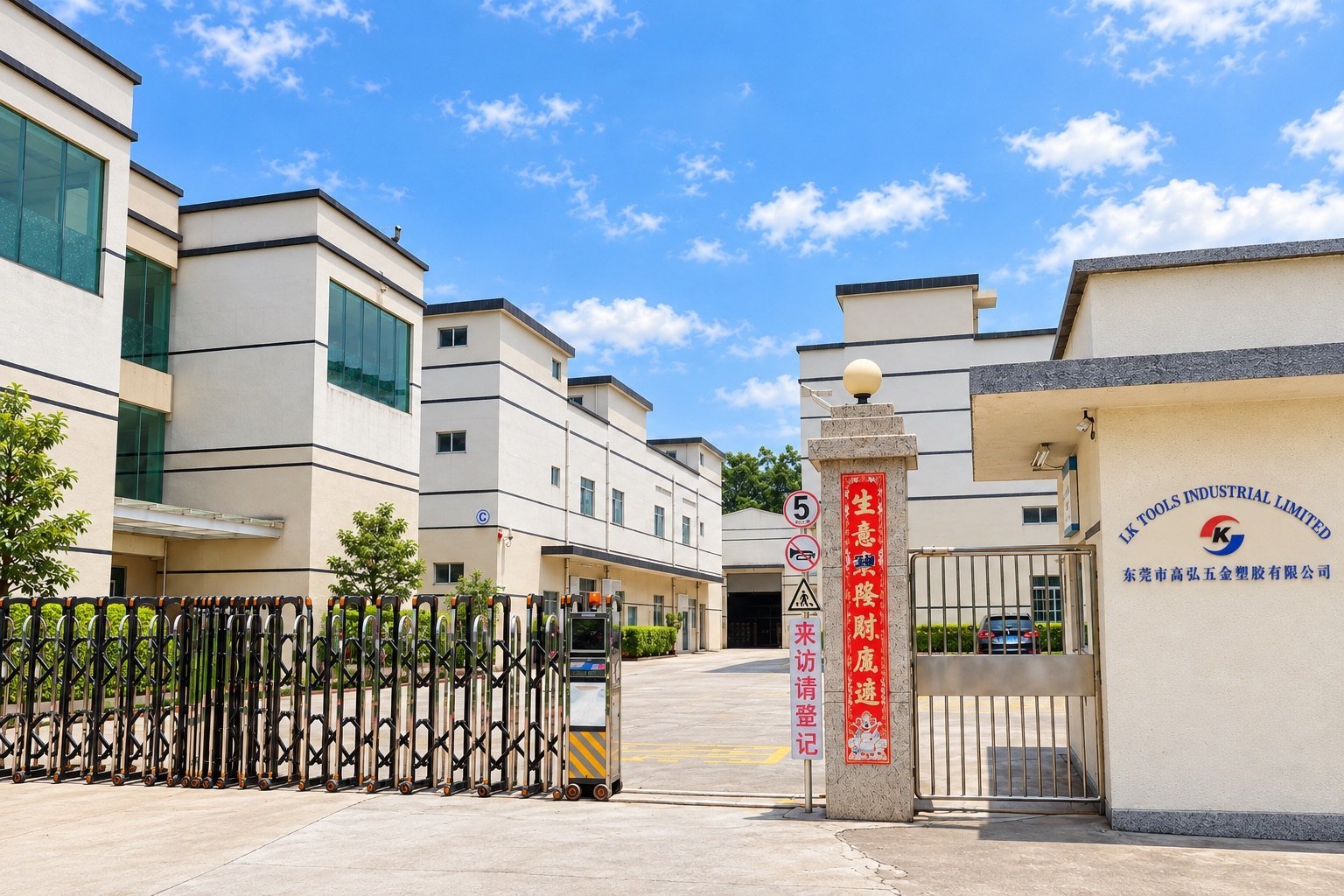
Connect China manufacturing with Dallas-area coordination for your drawing review, sample decisions and delivery requirements.
Define the exact grade, section, geometry and required working condition with the treatment provider. Reserve suitable finishing stock and recover the final datums where needed. Air hardening does not guarantee unchanged dimensions.
Agree the allowance for the actual part, thermal route, surface condition and final tolerance. Separate stock per surface from stock on a diameter. A value used on another tool is not an acceptance rule for your part.
Separate supplied hardness from the final working requirement. State the accepted condition, test method and locations, and the features that must be checked afterward. Do not assign one hardness to every A2 application.
Yes, review corrosion exposure and protection. A2 tool steel is not the A2 stainless fastener designation. Agree storage, handling, surface protection and the final working-face requirements for your environment.
Treat repair or joining as a separate engineering decision. Identify the steel, prior treatment, section, joint and required final condition. Agree a qualified procedure and final acceptance before committing to a repair.
Compare the actual product, wear and impact needs, edge support, section and manufacturing route. Use your failure mode and final acceptance requirements to approve an alternative; the grade name or chromium content alone cannot decide it.
For your A2 tool steel machining quote, send CAD, the controlled drawing, quantities, supplied condition, target working condition, critical tolerances, finishing and required records. Compare quotations at the same drawing revision and final state.





