

Injection Molding
Tooling and molding for your repeat plastic parts.
From prototype to production, coordinated manufacturing solutions for your custom parts.
View All Services →
Precision parts for your tight tolerances and complex geometry.
Tooling and molding for your repeat plastic parts.

Metal casting options for your part and production volume.

Cutting, forming and welding for your fabricated parts.

Custom profiles for your section, length and finish requirements.

Finishes for your appearance, corrosion and wear requirements.

Sub-assemblies and final builds for your production program.

Production tooling built around your process and volume.

Prototype parts to check fit, function and design.
DFM, process planning and production support for your project.
Inspection, documentation, inventory and delivery planning for your program.
Choose air- or liquid-cooling components around your thermal and mechanical requirements.

Manufacturing support for your cold plates, manifolds and cooling assemblies.

Find components for your power electronics, energy, laser and telecom application.

Components for your electronic systems.
Start with your functional and quality requirements.
Build around your operating environment.
From prototype to production, review material performance, manufacturability and cost for your part.
Review grade, temper and finish for your metal parts.
 AluminumStrength, weight and machining›
 Stainless SteelCorrosion and finish requirements›
 Carbon & Alloy SteelDiscuss grade and heat treatment›
 Tool SteelDiscuss tooling and wear needs›
 TitaniumReview grade and part geometry›
 Copper & Brass & BronzeDiscuss conductivity and machining›
Match your polymer to function, process and environment.
 ABSReview enclosure and molding needs›
 Polycarbonate (PC)Discuss clarity and impact needs›
 Nylon (PA)Review moisture and wear conditions›
 POM / AcetalReview fit and sliding features›
 PEEKDiscuss operating conditions›
 PTFEReview friction and chemical exposure›
 ULTEM / PEIDiscuss thermal and electrical needs›
Confirm grade availability and application requirements.
 Silicone / LSRDiscuss flexible component needs›
 TPU / TPEReview flexibility and processing›
 EPDMReview weathering and chemical exposure.›
 NBRReview oil and fuel exposure.›
 FKMReview temperature and chemical exposure.›
 G10 / FR4Review insulation and laminate needs›
 CompositesReview stiffness, weight and laminate.›Customer-Specified MaterialsConfirm your grade and requirements.›Other Specialty MaterialsDiscuss your application and grade.›
Practical guidance for your part geometry and material decisions.
Prepare your process, budget and sourcing questions.
Build your knowledge before production.
Learn who we are and how we operate.
Find our U.S. support team or start a conversation.
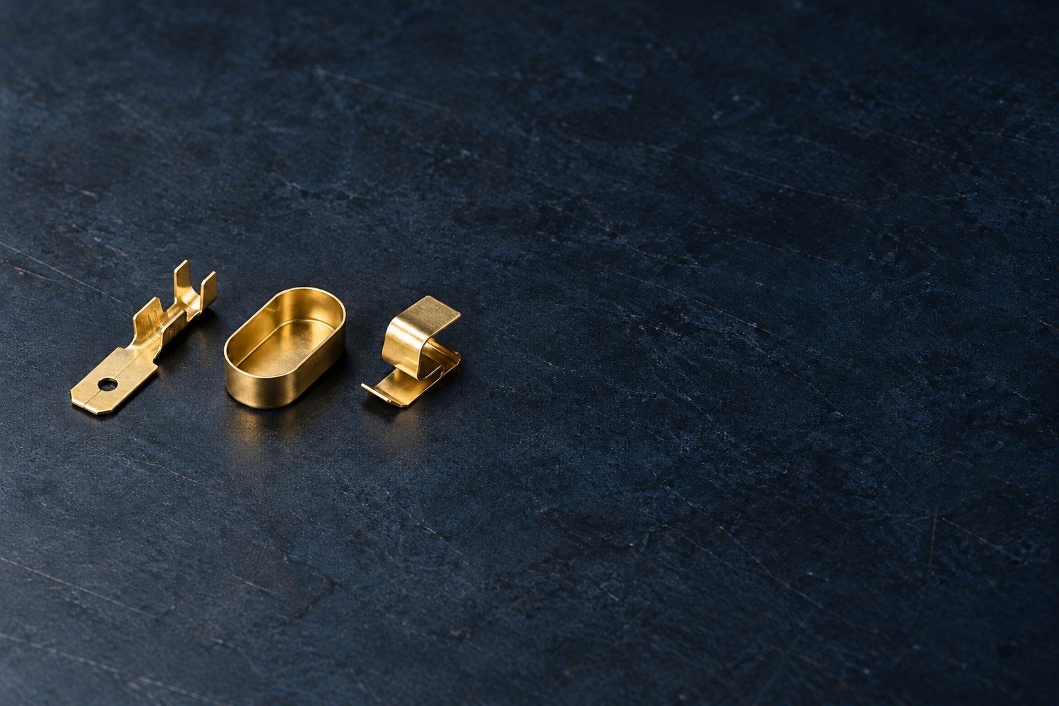
For your C260 brass stamping services quote, connect strip thickness, temper and rolling direction to the final shape. Define contact faces, accepted edges and the first formed sample.
For C26000 stamping, confirm the complete stock specification before you choose the forming route. A nominal 70/30 name does not set your strip temper, bend limit or final contact requirement.
| Identifier | Your purchasing input |
|---|---|
| UNS | C26000 brass / UNS C26000 |
| Common name | Cartridge brass / 70 30 brass · nominal designation |
| European reference | CuZn30 / CW505L · compare complete standard |
| Stock | Sheet or strip, thickness, temper and rolling direction |
| Acceptance | Final formed geometry, functional edges and lot records |
| Element · wt.% | US reference | EN reference |
|---|---|---|
| Copper | 68.5–71.5 | 69–71 |
| Iron | ≤0.05 | ≤0.05 |
| Lead | ≤0.07 | ≤0.05 |
| Zinc | Remainder | Remainder |
Separate Aurubis US and EN datasheets; selected elements only, not a merged acceptance specification or lot analysis. The US reference also specifies Cu plus named elements ≥99.7%; the EN reference lists additional residual limits. Your complete ordered standard governs.
| Input | Your forming decision |
|---|---|
| Thickness | Actual stock thickness and permissible variation. |
| Direction | Rolling direction relative to each critical bend. |
| Finished function | Contact force, assembly fit, appearance and accepted edges. |
These separate EN references show why strength and ductility must be considered together. They are not U.S. temper conversions or proof that your drawn or bent part will succeed.
Aurubis EN condition reference · MPa · common scale 0–600
Aurubis EN condition reference · A50 % · common scale 0–50
Selected Aurubis EN_2024_06 CuZn30 values for the named R conditions. Tensile intervals and A50 minima are material reference data, not finished-part results, press settings, bend radii, forming limits or automatic substitution approval. Confirm the producer data applicable to your ordered product and thickness.
Aurubis US C26000 reference ↗ Aurubis EN CuZn30 reference ↗ Wieland material designations ↗
Select a thin formed geometry, then review the strip, tool route and receiving evidence your part needs.
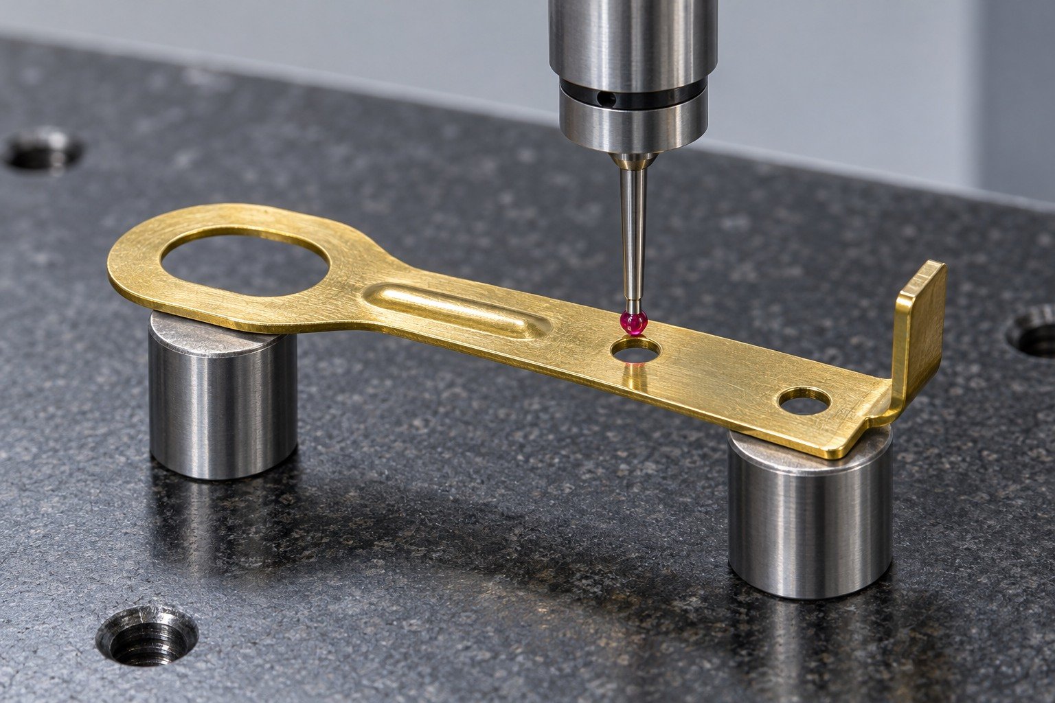
For your custom C260 brass stampings, define the terminal by its eyelet opening, locating holes, stiffening bead and connection tongue. Keep working contact areas separate from handling and tooling marks.
| Your decision | What to define |
|---|---|
| Your fit | Eyelet position, mounting-hole pattern, tongue angle and accepted edge direction. |
| Your route | Stock condition, support and finishing sequence. |
| Your approval | Final geometry, surface and receiving evidence. |
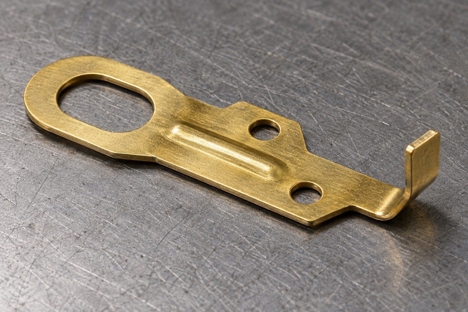
For C260 brass blanking and C260 brass piercing, review strip support, pilot locations and the operation sequence around critical contact features.
| Your decision | What to define |
|---|---|
| Your fit | Eyelet position, mounting-hole pattern, tongue angle and accepted edge direction. |
| Your route | Stock condition, support and finishing sequence. |
| Your approval | Final geometry, surface and receiving evidence. |
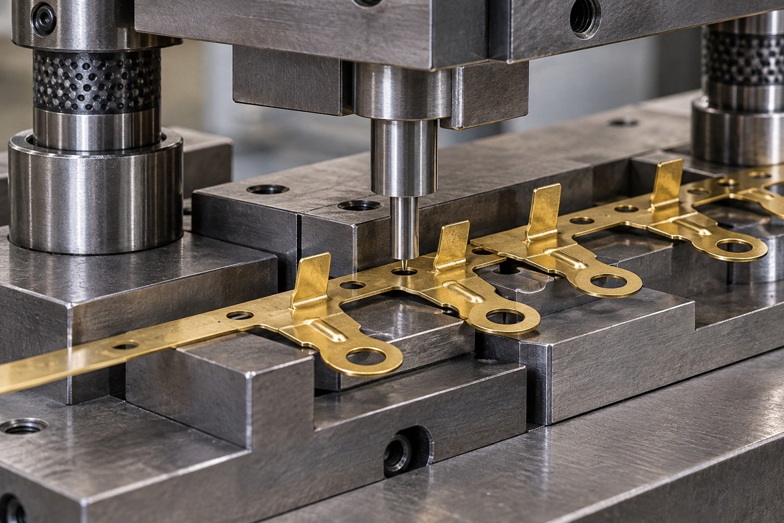
Confirm strip thickness and C260 brass temper before a forming trial. Mark the rolling direction and the condition required at final inspection.
| Your decision | What to define |
|---|---|
| Your fit | Eyelet position, mounting-hole pattern, tongue angle and accepted edge direction. |
| Your route | Stock condition, support and finishing sequence. |
| Your approval | Final geometry, surface and receiving evidence. |
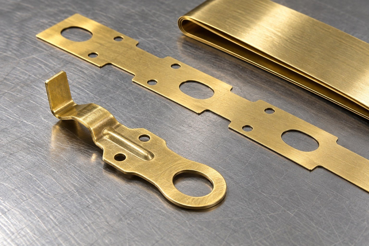
Verify hole-to-contact relationships and tongue geometry after forming. Agree edge acceptance and protection of the working face.
| Your decision | What to define |
|---|---|
| Your fit | Eyelet position, mounting-hole pattern, tongue angle and accepted edge direction. |
| Your route | Stock condition, support and finishing sequence. |
| Your approval | Final geometry, surface and receiving evidence. |
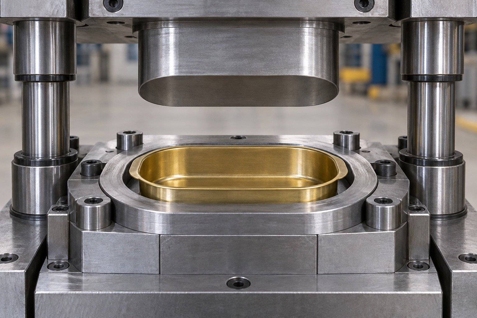
Review a shallow enclosure cup by its closed base, corner transitions and mounting rim. Define the actual depth and final wall requirements before deciding a drawing sequence.
| Your decision | What to define |
|---|---|
| Your fit | Rim datums, enclosure depth, corner geometry and pierced mounting pattern. |
| Your route | Stock condition, support and finishing sequence. |
| Your approval | Final geometry, surface and receiving evidence. |

For C260 brass deep drawing, agree the blank and forming sequence against your depth, wall geometry and cosmetic requirement. Any intermediate operation belongs in the reviewed route.
| Your decision | What to define |
|---|---|
| Your fit | Rim datums, enclosure depth, corner geometry and pierced mounting pattern. |
| Your route | Stock condition, support and finishing sequence. |
| Your approval | Final geometry, surface and receiving evidence. |
Confirm sheet or strip state, thickness and grain requirement. Do not treat a successful shallow trial as proof for a deeper or thinner enclosure.
| Your decision | What to define |
|---|---|
| Your fit | Rim datums, enclosure depth, corner geometry and pierced mounting pattern. |
| Your route | Stock condition, support and finishing sequence. |
| Your approval | Final geometry, surface and receiving evidence. |

Inspect the rim and required wall features after drawing and trimming. Agree the acceptance of thinning, surface marks and any required tests.
| Your decision | What to define |
|---|---|
| Your fit | Rim datums, enclosure depth, corner geometry and pierced mounting pattern. |
| Your route | Stock condition, support and finishing sequence. |
| Your approval | Final geometry, surface and receiving evidence. |

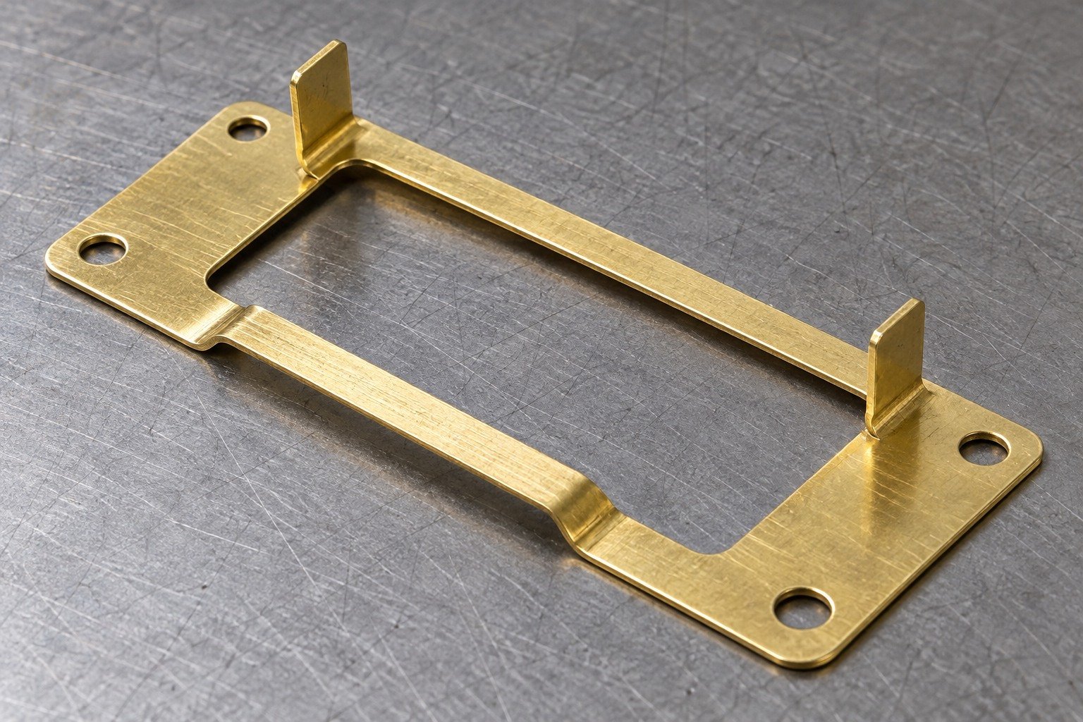
Connect a pierced connector frame to its actual opening, folded locating tabs and mounting step. Define the final assembly references before choosing the tool layout.
| Your decision | What to define |
|---|---|
| Your fit | Opening size, tab angle, offset height, mounting holes and datum scheme. |
| Your route | Stock condition, support and finishing sequence. |
| Your approval | Final geometry, surface and receiving evidence. |
Review C260 brass progressive stamping as a quoted route where suitable; connect pilot layout, forming stations and part release to the actual geometry.
| Your decision | What to define |
|---|---|
| Your fit | Opening size, tab angle, offset height, mounting holes and datum scheme. |
| Your route | Stock condition, support and finishing sequence. |
| Your approval | Final geometry, surface and receiving evidence. |

Keep thickness, supplied state and rolling direction in the controlled stock requirement. Review any route change against the same final connector function.
| Your decision | What to define |
|---|---|
| Your fit | Opening size, tab angle, offset height, mounting holes and datum scheme. |
| Your route | Stock condition, support and finishing sequence. |
| Your approval | Final geometry, surface and receiving evidence. |

Verify opening-to-tab relationships, formed heights and accepted edges in the final state. Define which tooling witness marks are permissible.
| Your decision | What to define |
|---|---|
| Your fit | Opening size, tab angle, offset height, mounting holes and datum scheme. |
| Your route | Stock condition, support and finishing sequence. |
| Your approval | Final geometry, surface and receiving evidence. |

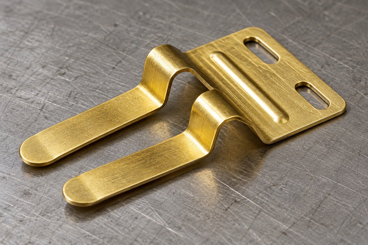
Define a folded contact clip by its parallel fingers, gap and mounting foot. Your specification must state contact force and working deflection if those functions are required.
| Your decision | What to define |
|---|---|
| Your fit | Finger gap, inside bend, slot position, mounting datum and functional contact face. |
| Your route | Stock condition, support and finishing sequence. |
| Your approval | Final geometry, surface and receiving evidence. |
For C260 brass forming and C260 brass bending, review support at each bend, rolling direction and the sequence that protects the contact tongue.
| Your decision | What to define |
|---|---|
| Your fit | Finger gap, inside bend, slot position, mounting datum and functional contact face. |
| Your route | Stock condition, support and finishing sequence. |
| Your approval | Final geometry, surface and receiving evidence. |

Select the actual supplied condition with the final functional requirement. A bright yellow appearance does not establish spring performance or temper.
| Your decision | What to define |
|---|---|
| Your fit | Finger gap, inside bend, slot position, mounting datum and functional contact face. |
| Your route | Stock condition, support and finishing sequence. |
| Your approval | Final geometry, surface and receiving evidence. |
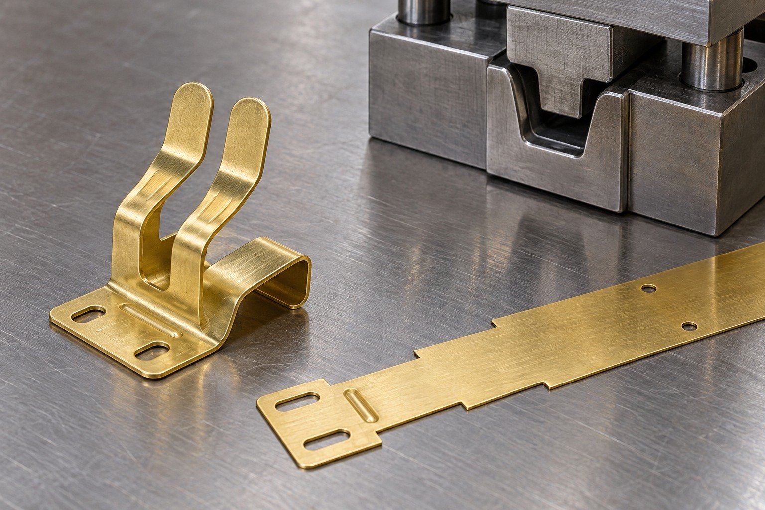
Check the final gap, angle and mounting plane after the agreed route. Any force or deflection test requires a separate defined acceptance scope.
| Your decision | What to define |
|---|---|
| Your fit | Finger gap, inside bend, slot position, mounting datum and functional contact face. |
| Your route | Stock condition, support and finishing sequence. |
| Your approval | Final geometry, surface and receiving evidence. |
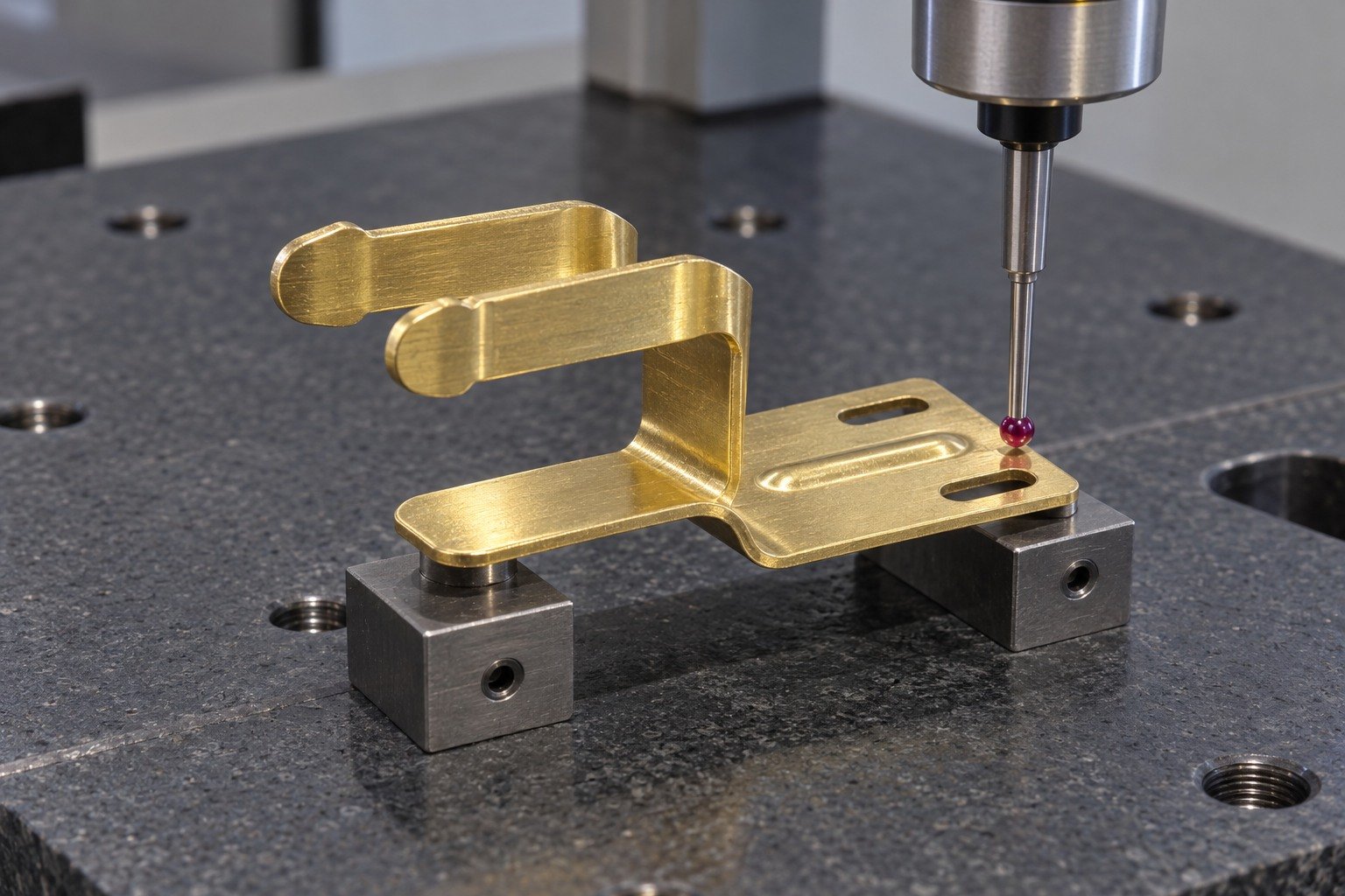
For your C260 brass stamping services review, define the operations, quantities and first-sample scope against the controlled drawing. Your quotation confirms the accepted route.

Review blank outline, hole position, strip pilots and accepted burr direction.
Explore the Process →
Plan bend sequence and supported tooling around the final contact geometry.
Explore the Process →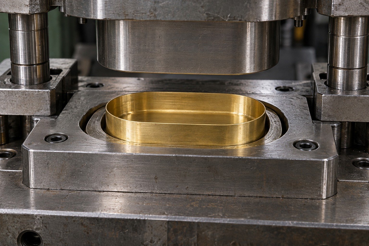
Review shallow enclosure geometry, rim support and the complete drawing route.
Explore the Process →
Verify locating holes, formed height and contact datums after all operations.
Explore the Process →Review material state, pierced edges, forming sequence and final measurement together.
For C260 brass precision stamping, define thickness, temper, rolling direction and critical working surfaces. Review the actual supplied material before releasing a tool or strip layout.
Show the working feature and allowed edge condition.
Agree stock, support and final surface.
Inspect the actual finished state.

Show hole-to-bend distances, slot ends, accepted burr direction and the functional mating edges. For C260 brass deburring, define the allowed edge break and protected contact geometry. Agree which dimensions are inspected before or after forming.
Show the working feature and allowed edge condition.
Agree stock, support and final surface.
Inspect the actual finished state.

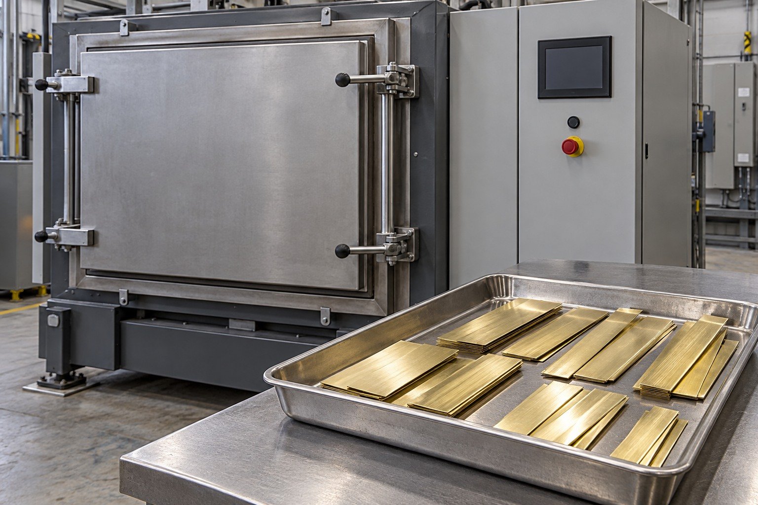
Confirm whether a specified anneal belongs in the route, who controls it and which final condition is required. Do not assume that a generic heat step preserves finish, dimensions or contact function.
Show the working feature and allowed edge condition.
Agree stock, support and final surface.
Inspect the actual finished state.
For C260 brass bend radius review, connect actual thickness, supplied state, rolling direction and final angle. Resolve springback and bend transitions through an agreed first trial; no universal radius is promised.
Show the working feature and allowed edge condition.
Agree stock, support and final surface.
Inspect the actual finished state.
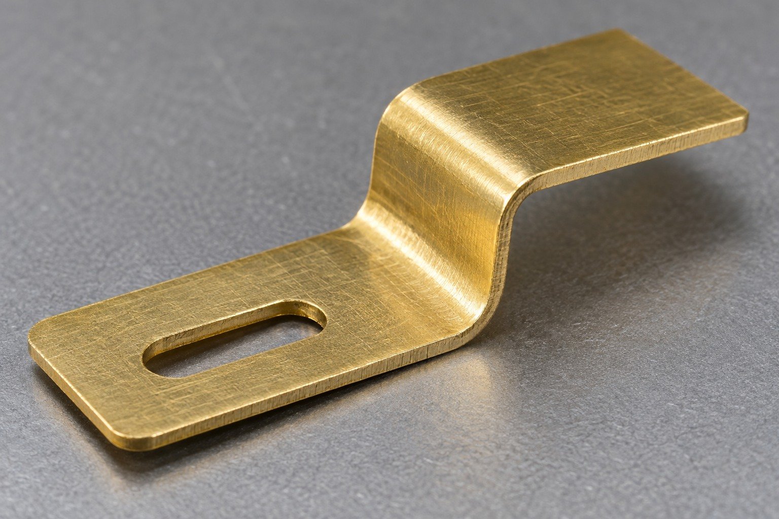
Define surface condition, cosmetic areas, cleaning, masking and packaging. Review any plating or coating for fit and contact function before approving the finished part.
Show the working feature and allowed edge condition.
Agree stock, support and final surface.
Inspect the actual finished state.
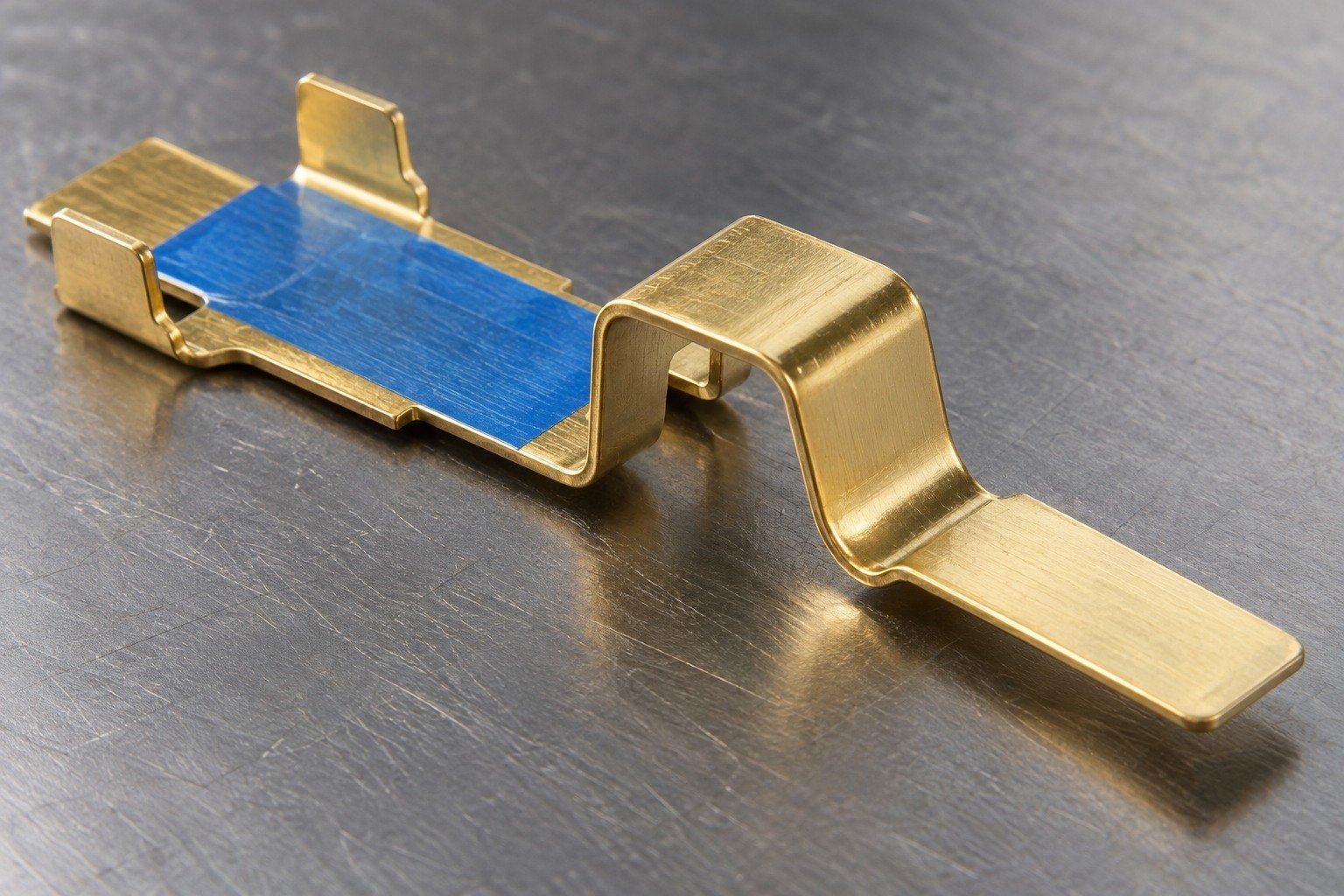
Identify formed datums, supported measurement and the condition of final inspection. Separate flat blank dimensions from formed-part acceptance rather than quoting one tolerance for every feature.
Show the working feature and allowed edge condition.
Agree stock, support and final surface.
Inspect the actual finished state.
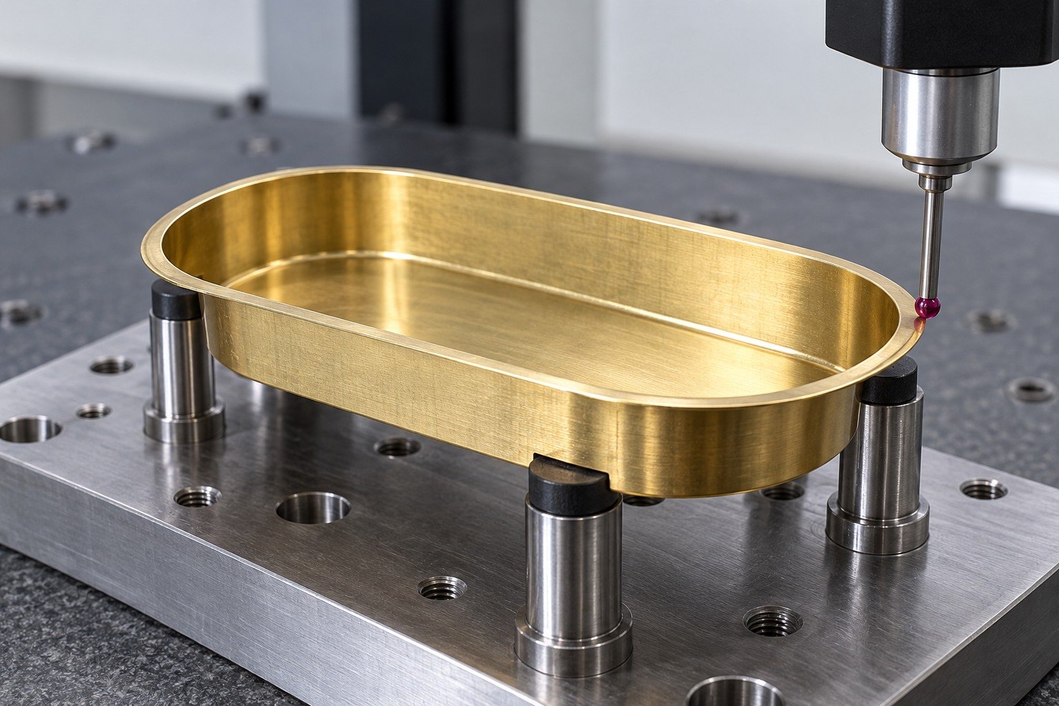
| Comparison | Your approval input |
|---|---|
| C260 vs C360 brass | Keep forming and chip-machining requirements distinct; review the complete material specification. |
| C260 vs C268 brass | Confirm chemistry, temper, product form and the actual forming requirement. |
| Cartridge brass / C260 | Nominal naming does not define thickness, supplied state or final acceptance. |
A similar colour or common name does not approve substitution. Obtain drawing-authority approval before changing stock.
Compare Copper, Brass & Bronze →


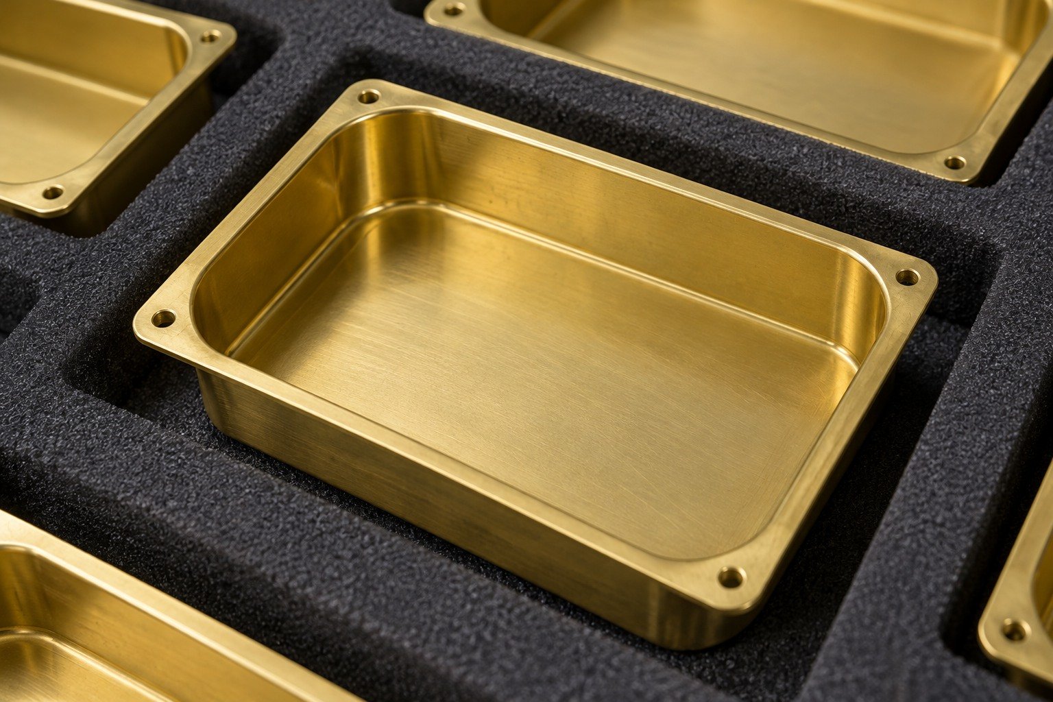
Illustrative appearances. State permitted tooling marks, working contact faces and protection. Any coating or plating needs its own suitability and final-fit review.
Surface Finishing →Grade, product form, temper and lot.
Contact features and accepted edges.
Final fit, surface and records.
For your C260 brass material certificate, agree the exact standard, thickness, supplied temper, lot identity and document scope before ordering stock.
Sampling and evidence scope are agreed with your quote.
Quality Assurance →
Review the complete formed sample against locating datums, bend transitions and accepted edges before repeat quantities. Confirm whether trial tooling represents the final route.
Sampling and evidence scope are agreed with your quote.
Quality Assurance →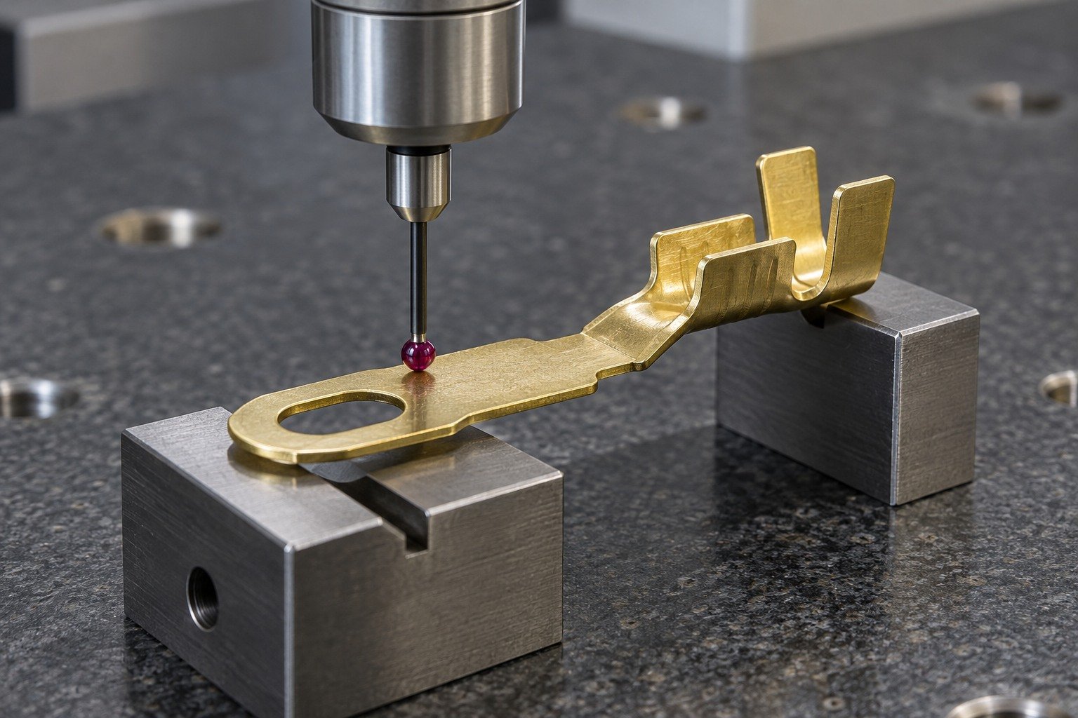
Inspect contact gap, formed height, hole relationships and accepted working surfaces after the complete route. Agree support and measurement access for thin features.
Sampling and evidence scope are agreed with your quote.
Quality Assurance →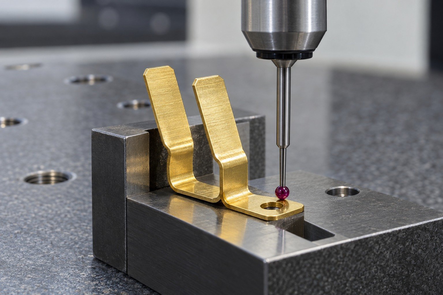
Agree individual protection, identification and receiving records for the delivered lot. Protect thin tabs and cosmetic contact faces from part-on-part damage.
Sampling and evidence scope are agreed with your quote.
Quality Assurance →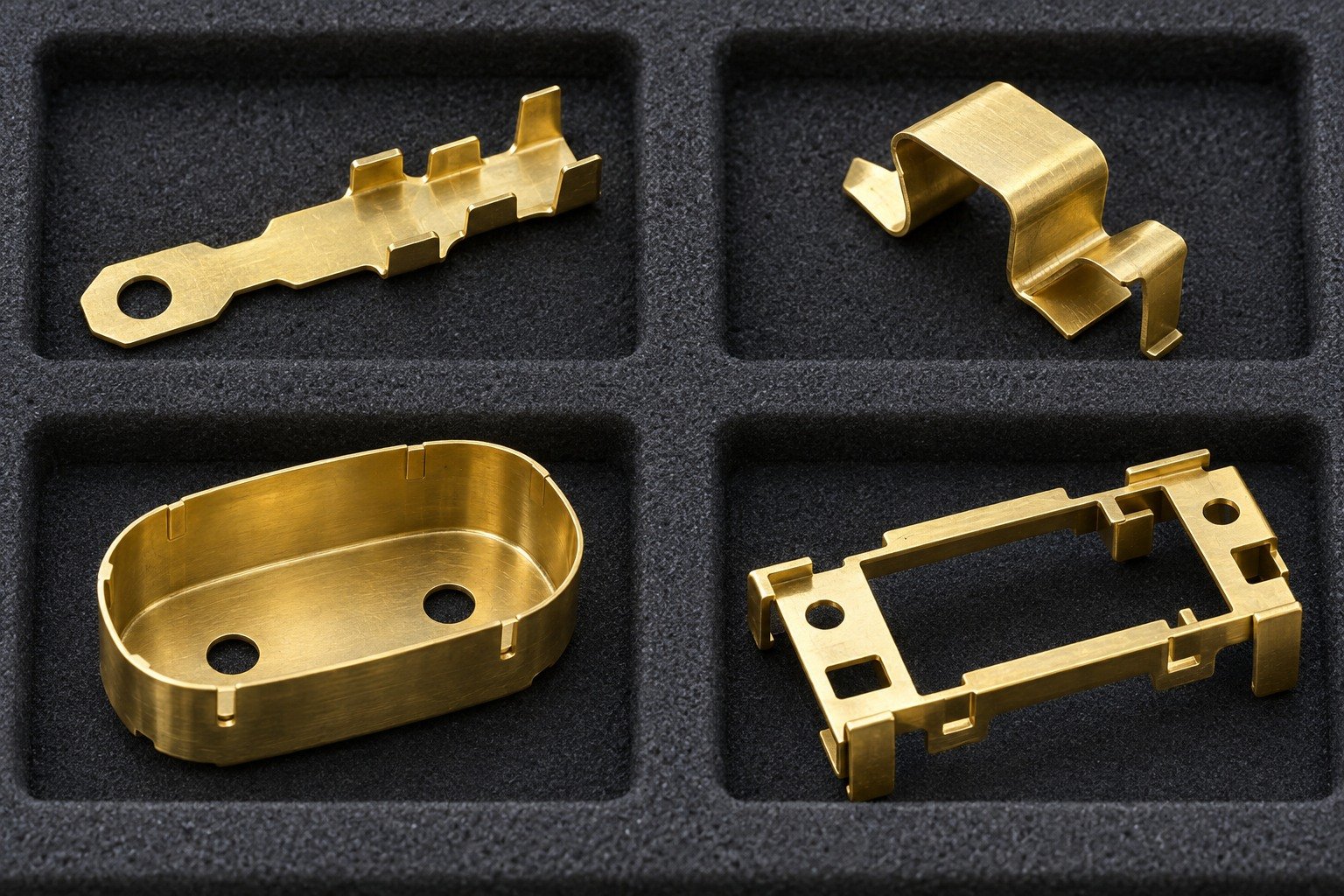

Connect China manufacturing with Dallas-area coordination for drawing review, sample decisions and delivery requirements.
Define the exact product standard, thickness, rolling direction and final part function, then agree the supplied state through a forming trial. There is no single temper choice for every terminal, clip and drawn enclosure.
Producer references describe C260 / CuZn30 as a cold-forming material, but your depth, wall shape, thickness and state determine the actual drawing review. Agree the trial and full route before promising a finished enclosure.
Review supplied temper, rolling direction, bend transitions, edge quality and the operation sequence against the actual geometry. Record first-sample acceptance; do not treat a material name as a guarantee against cracking.
State the required inside radius, actual thickness, bend direction relative to rolling and final angle. Apply the producer reference relevant to the ordered material and verify your tooling trial; no universal minimum is quoted.
Do not assume interchangeability. Compare full chemistry, supplied condition and forming requirement with the actual finished function. A material suited to chip machining does not automatically meet your stamping route.
Confirm the exact grade, product standard, stock state and acceptance of the final formed geometry. Similar names and appearance do not approve a change to your purchase specification.
Your C260 brass stamping quote depends on usable strip, blank layout, tooling and setup, forming stages, trial and repeat quantities, finish and inspection scope. For your C260 brass stamping manufacturer review, compare the same drawing and final requirement.
C26000 is commonly called cartridge brass or nominal 70/30 brass. Specify UNS C26000 and the full ordered product requirement; the common name alone does not set temper or guarantee the performance of your formed part.





