Injection Molding
Tooling and molding for your repeat plastic parts.
From prototype to production, coordinated manufacturing solutions for your custom parts.
View All Services →
Precision parts for your tight tolerances and complex geometry.
Tooling and molding for your repeat plastic parts.

Metal casting options for your part and production volume.

Cutting, forming and welding for your fabricated parts.

Custom profiles for your section, length and finish requirements.

Finishes for your appearance, corrosion and wear requirements.

Sub-assemblies and final builds for your production program.

Production tooling built around your process and volume.

Prototype parts to check fit, function and design.
DFM, process planning and production support for your project.
Inspection, documentation, inventory and delivery planning for your program.
Choose air- or liquid-cooling components around your thermal and mechanical requirements.

Manufacturing support for your cold plates, manifolds and cooling assemblies.

Find components for your power electronics, energy, laser and telecom application.

Components for your electronic systems.
Start with your functional and quality requirements.
Build around your operating environment.
From prototype to production, review material performance, manufacturability and cost for your part.
Review grade, temper and finish for your metal parts.
 AluminumStrength, weight and machining›
 Stainless SteelCorrosion and finish requirements›
 Carbon & Alloy SteelDiscuss grade and heat treatment›
 Tool SteelDiscuss tooling and wear needs›
 TitaniumReview grade and part geometry›
 Copper & Brass & BronzeDiscuss conductivity and machining›
Match your polymer to function, process and environment.
 ABSReview enclosure and molding needs›
 Polycarbonate (PC)Discuss clarity and impact needs›
 Nylon (PA)Review moisture and wear conditions›
 POM / AcetalReview fit and sliding features›
 PEEKDiscuss operating conditions›
 PTFEReview friction and chemical exposure›
 ULTEM / PEIDiscuss thermal and electrical needs›
Confirm grade availability and application requirements.
 Silicone / LSRDiscuss flexible component needs›
 TPU / TPEReview flexibility and processing›
 EPDMReview weathering and chemical exposure.›
 NBRReview oil and fuel exposure.›
 FKMReview temperature and chemical exposure.›
 G10 / FR4Review insulation and laminate needs›
 CompositesReview stiffness, weight and laminate.›Customer-Specified MaterialsConfirm your grade and requirements.›Other Specialty MaterialsDiscuss your application and grade.›
Practical guidance for your part geometry and material decisions.
Prepare your process, budget and sourcing questions.
Build your knowledge before production.
Learn who we are and how we operate.
Find our U.S. support team or start a conversation.
YOUR FEATURES. YOUR MATERIAL. YOUR MANUFACTURING REVIEW.
Connect tool access, molded features and locating interfaces to the function of your part. Use this guide to prepare better questions before your design, process and inspection scope are agreed.
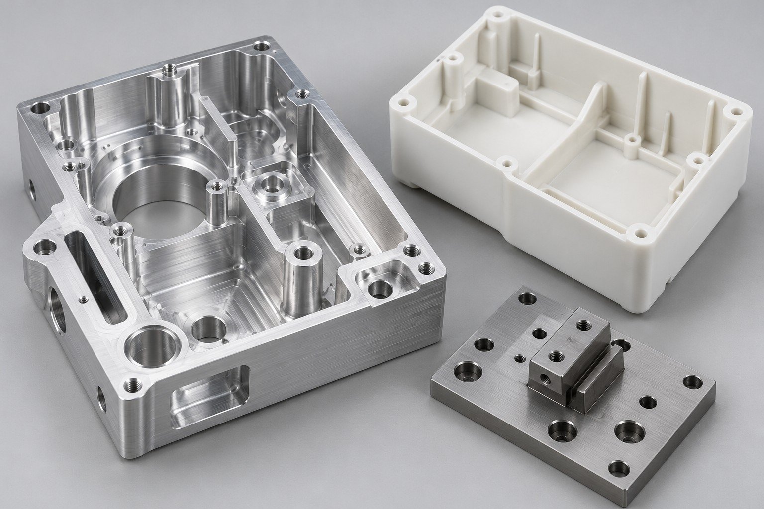
Use these CNC part design guidelines to review internal corners, pocket depth and tool access together. A small corner can constrain the available cutter even when the rest of the pocket is open.
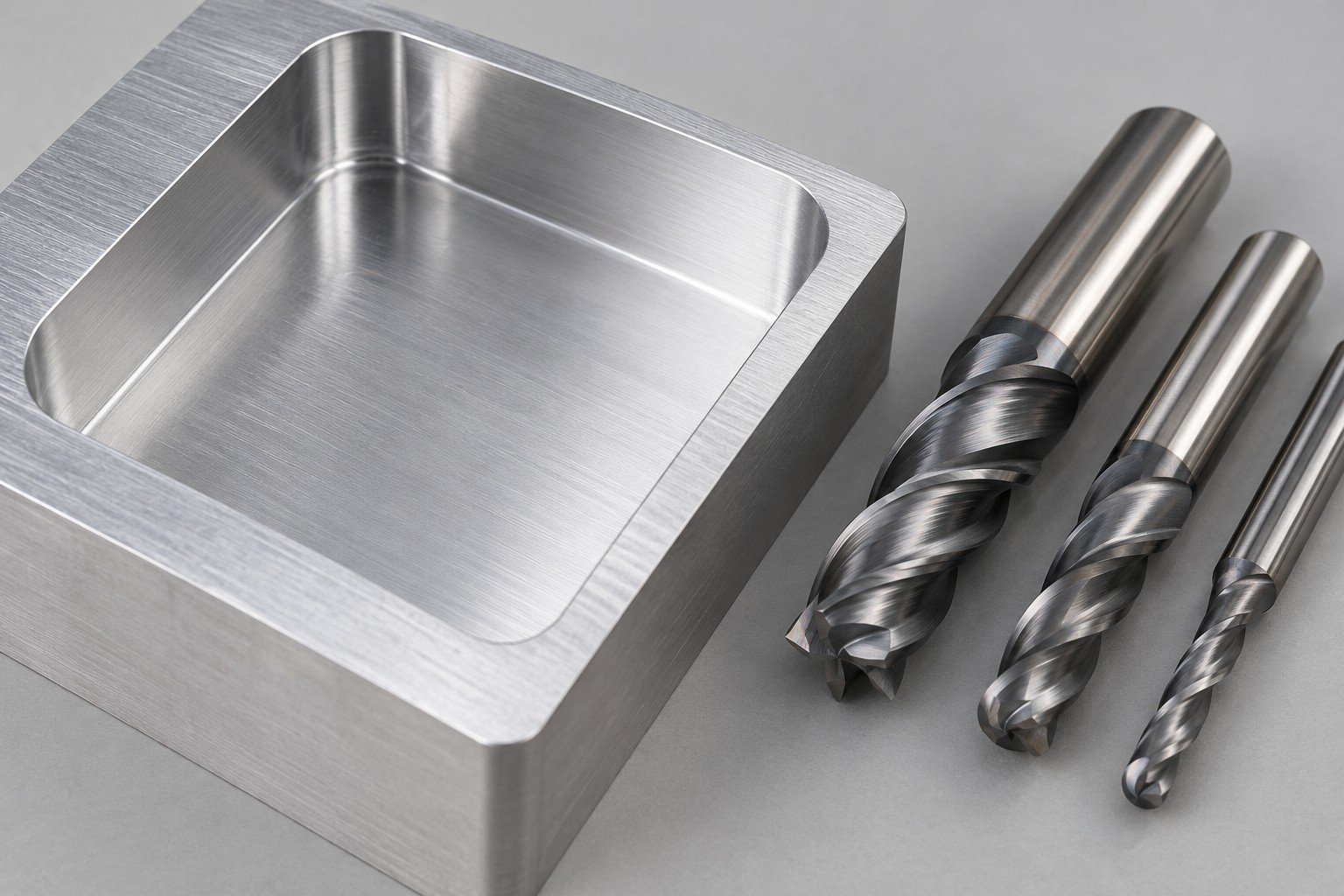
For a perpendicular cylindrical cutter in an idealized pocket: tool diameter ≤ 2 × internal corner radius. Zero baseline 0–8 mm.
These are geometric examples, not recommended cutters or process limits. Actual machining needs clearance, reach, material and vibration review; a smaller tool may be required.
The photograph illustrates rounded corners and has no assigned dimensions. Background reference: Protolabs on tool access and internal radii →. Tool geometry does not establish LK MFG capability or a quoted cycle time.
Review tool access, corner relief, reachable holes and the surfaces that control final fit. Review CNC manufacturing →
Review draft, wall transitions, ribs, resin and the expected appearance before tooling. Review molding →
Review bend access, hole-to-bend relationships, hardware and the assembled envelope. Review sheet metal →
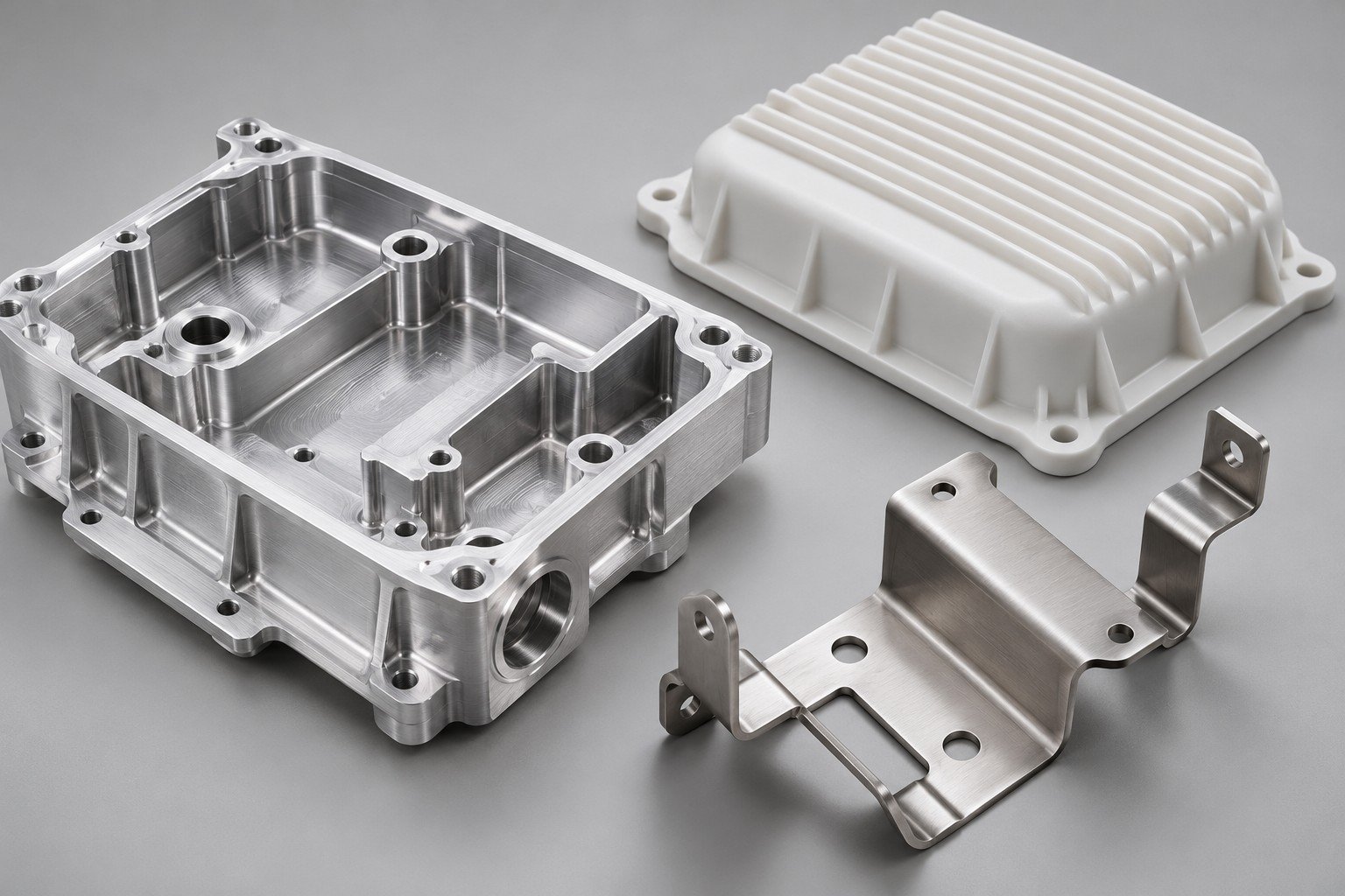
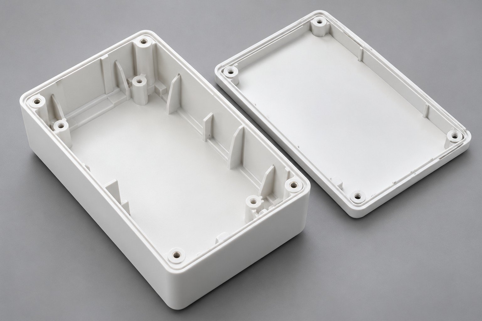
For injection mold design and build, review the finished part, tooling approach and resin together. A change to ribs, bosses or appearance may also change the mold and approval plan.
Review wall transitions, rib intersections and material accumulation against your resin and function. There is no universal wall thickness for every polymer.
Injection molding boss design guidelines depend on resin, mating hardware and tooling. Define the fastener, engagement and surrounding structure.
Identify release direction, texture, parting lines and visible surfaces. Agree cosmetic acceptance separately from dimensional requirements.
Reference topics: Xometry injection molding guide →. Supplier-specific limits are not adopted as LK MFG promises.
For tool and fixture design, identify the contact datums, supported surfaces and clamp access. A manufacturing fixture review does not replace your equipment design or application validation.
Show the features that establish position and orientation.
Identify supported faces and features that must not distort or be marked.
Consider cutting, assembly and inspection access in the intended setup.
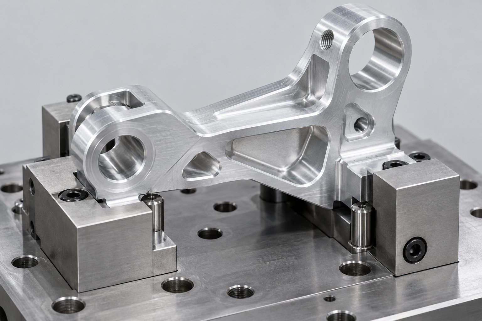
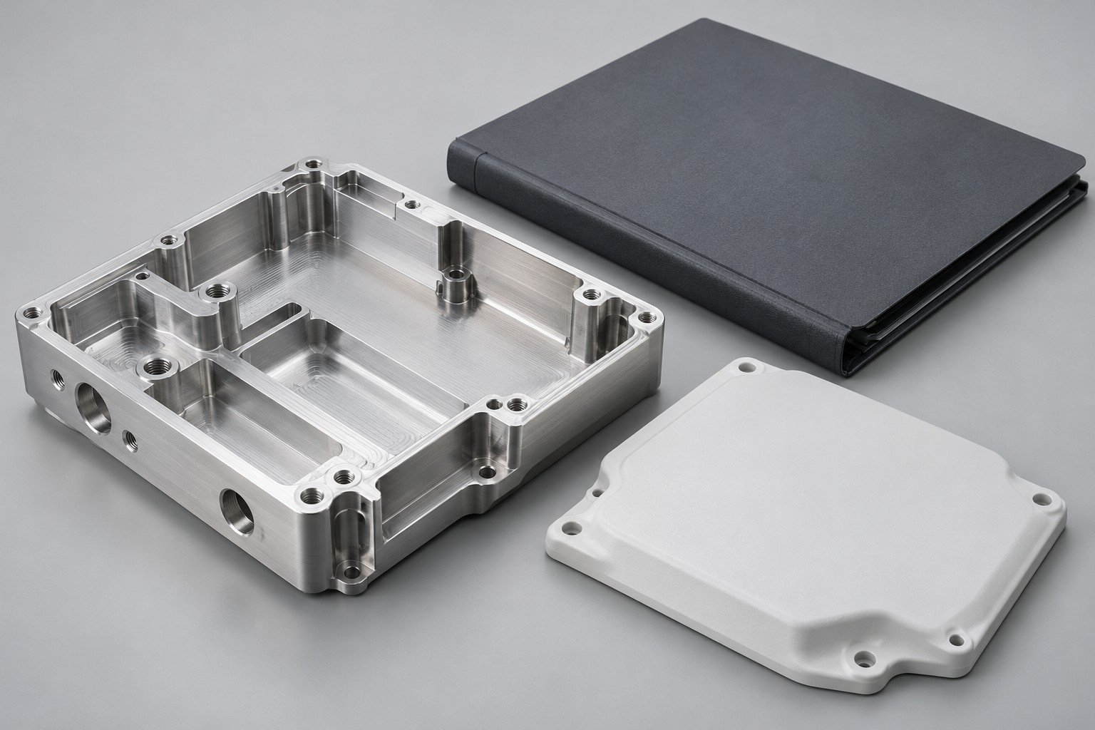
Identify the dimensions that control function and assembly. Agree the remaining requirements rather than tightening the complete drawing without a reason.
Use the model for geometry and define controlled units, tolerances, material, finish and acceptance requirements in the agreed drawing or specification.
A two-shot molding design guide must address resin compatibility, interface geometry, mold architecture and equipment requirements. Review availability and project scope before assuming this production route.
No. They explain a geometric relationship. Actual tool choice, setup, process limits and acceptance must be confirmed for your drawing.
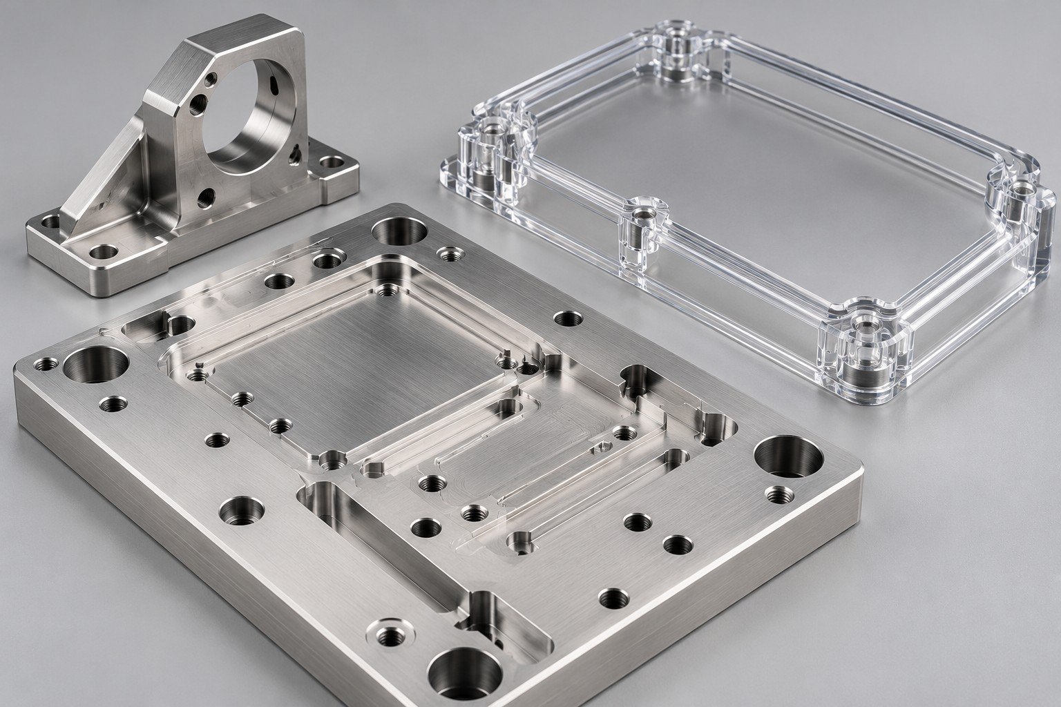
Connect tolerances, datums and inspection. Review tolerance and GD&T →
Compare the grade, geometry and manufacturing route. Review material and process selection →
Send a controlled baseline for a useful quote. Use the RFQ checklist →