Injection Molding
Tooling and molding for your repeat plastic parts.
From prototype to production, coordinated manufacturing solutions for your custom parts.
View All Services →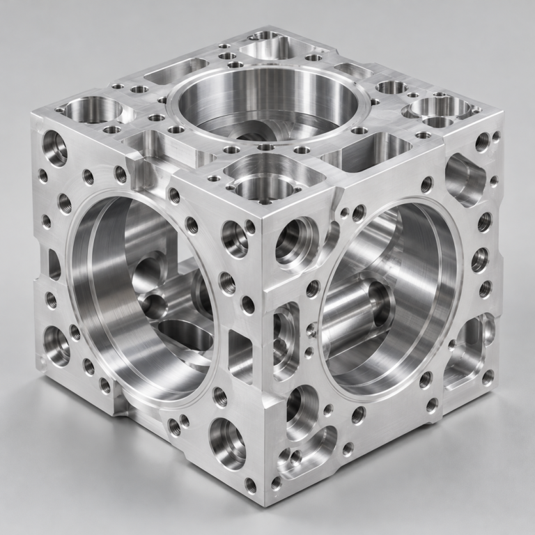
Precision parts for your tight tolerances and complex geometry.
Tooling and molding for your repeat plastic parts.
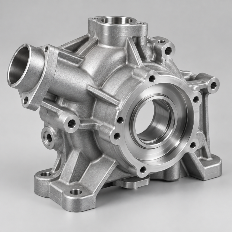
Metal casting options for your part and production volume.
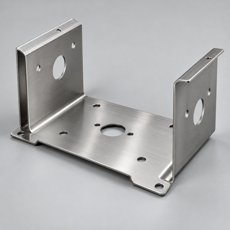
Cutting, forming and welding for your fabricated parts.
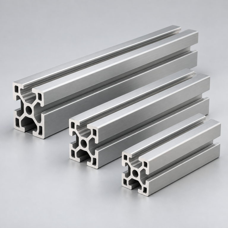
Custom profiles for your section, length and finish requirements.
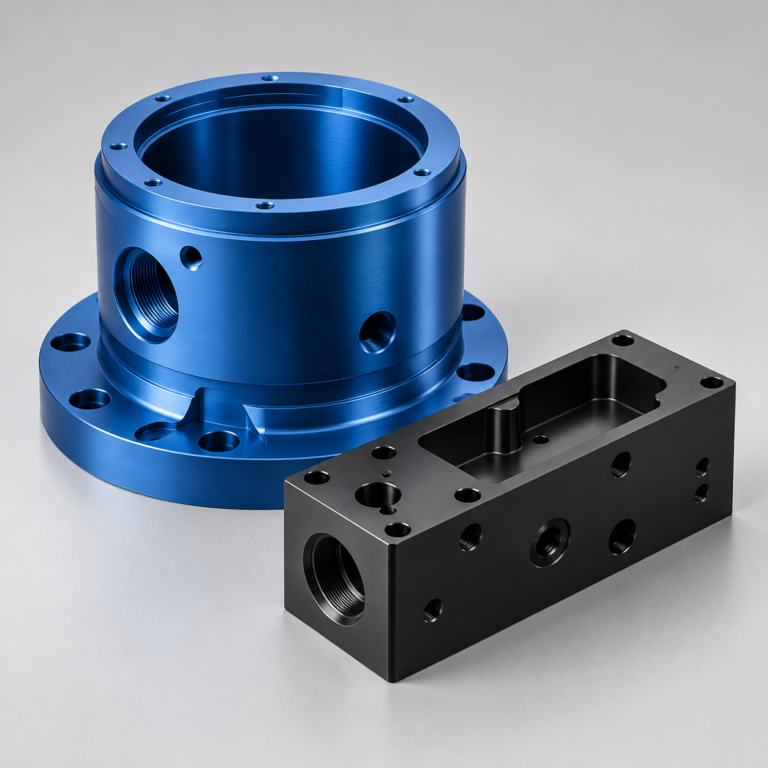
Finishes for your appearance, corrosion and wear requirements.
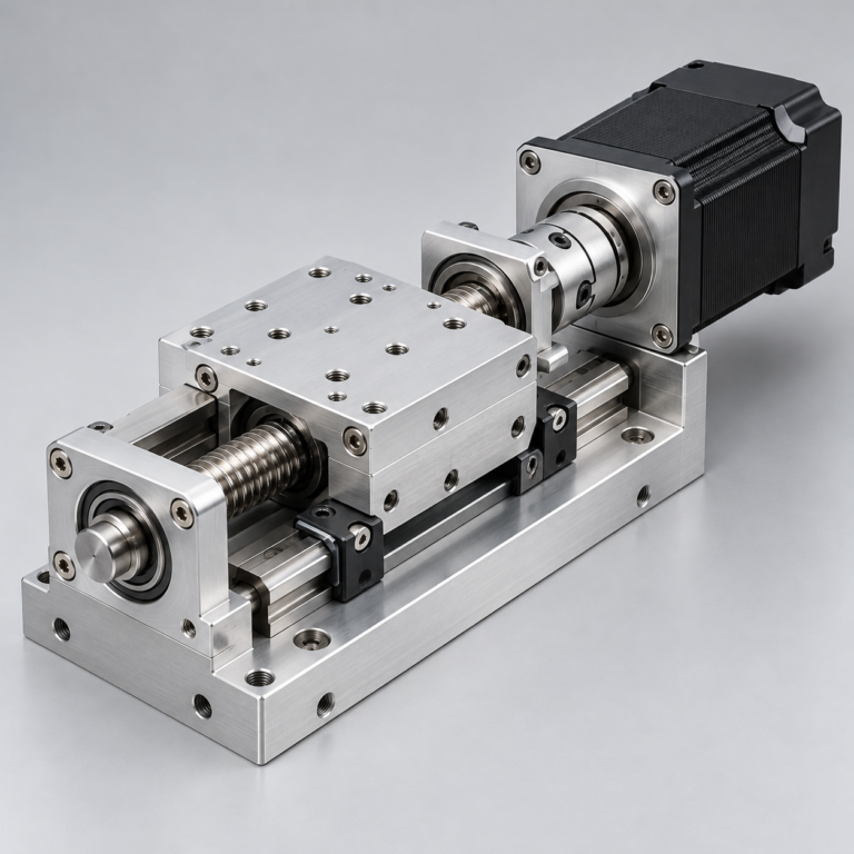
Sub-assemblies and final builds for your production program.
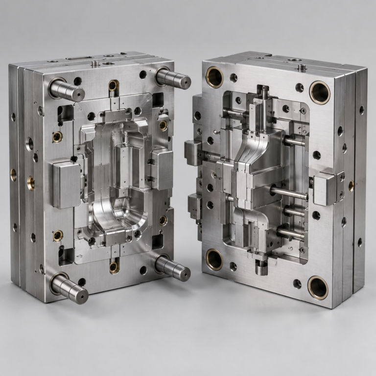
Production tooling built around your process and volume.
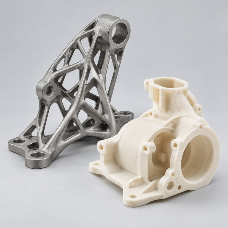
Prototype parts to check fit, function and design.
DFM, process planning and production support for your project.
Inspection, documentation, inventory and delivery planning for your program.
Choose air- or liquid-cooling components around your thermal and mechanical requirements.
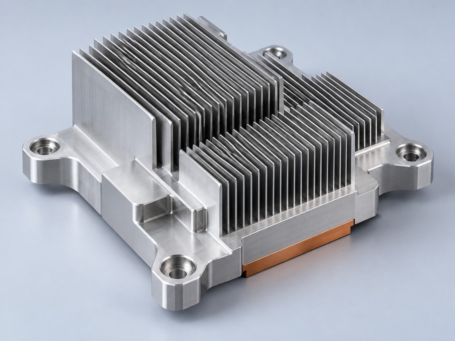
Manufacturing support for your cold plates, manifolds and cooling assemblies.
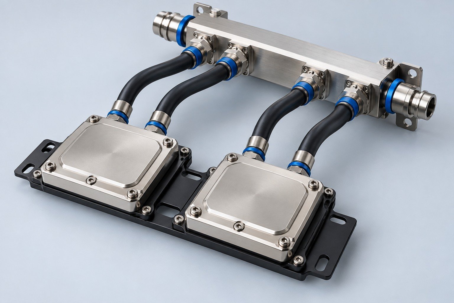
Find components for your power electronics, energy, laser and telecom application.
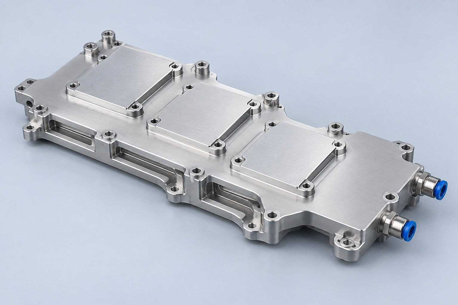
Components for your electronic systems.
Start with your functional and quality requirements.
Build around your operating environment.
From prototype to production, review material performance, manufacturability and cost for your part.
Review grade, temper and finish for your metal parts.
 AluminumStrength, weight and machining›
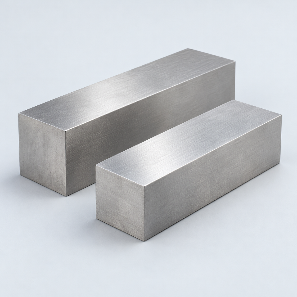 Stainless SteelCorrosion and finish requirements›
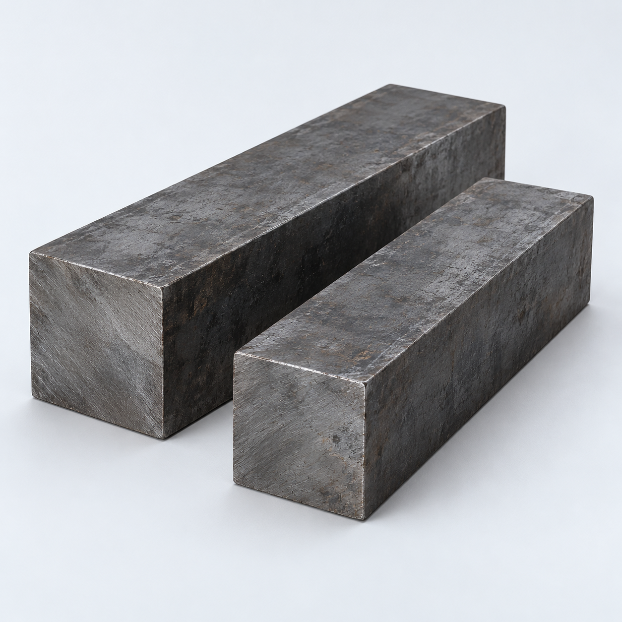 Carbon & Alloy SteelDiscuss grade and heat treatment›
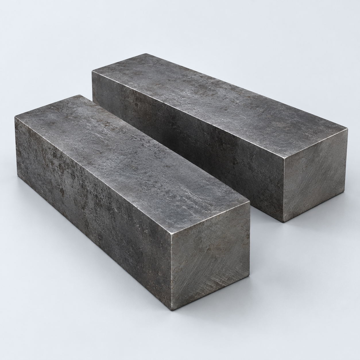 Tool SteelDiscuss tooling and wear needs›
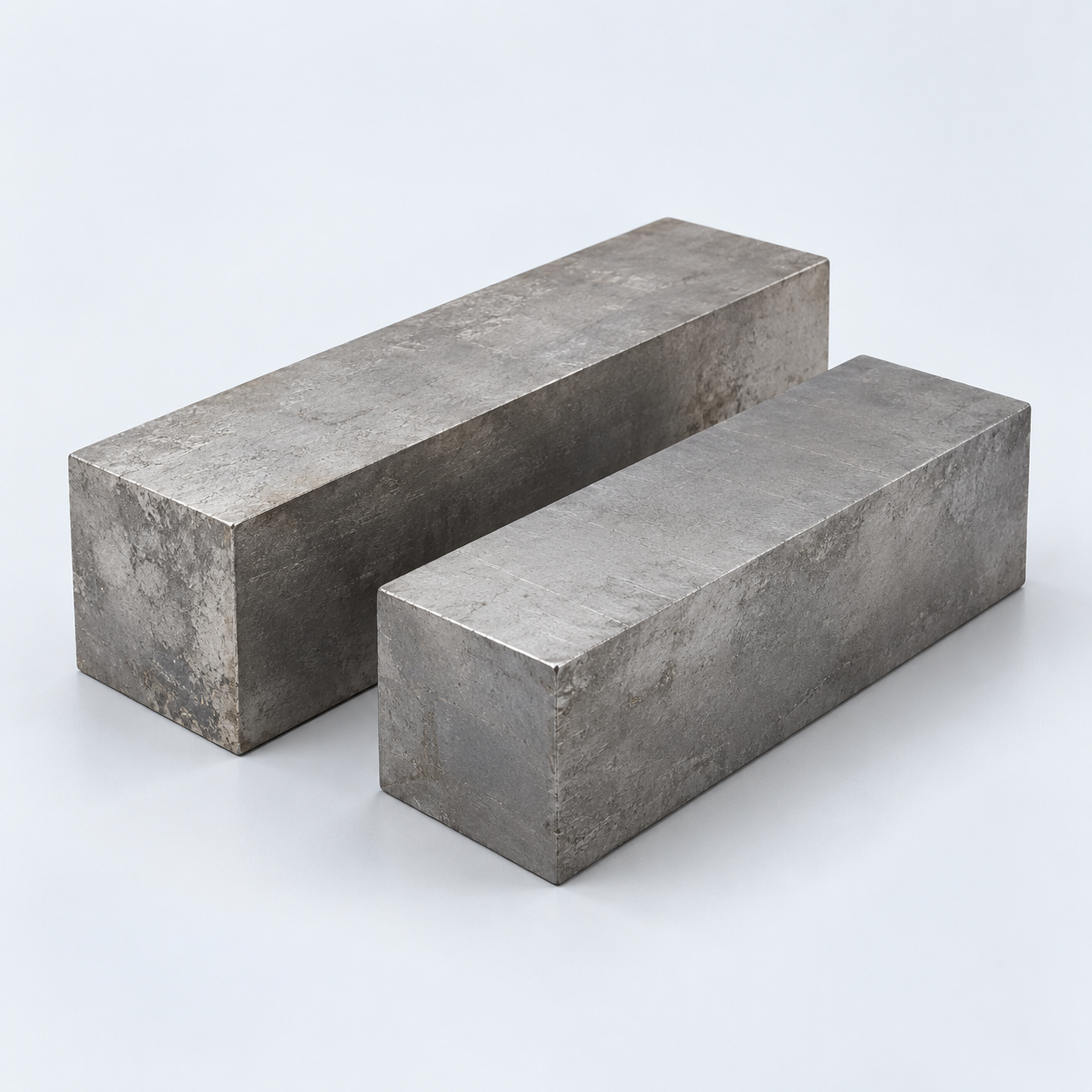 TitaniumReview grade and part geometry›
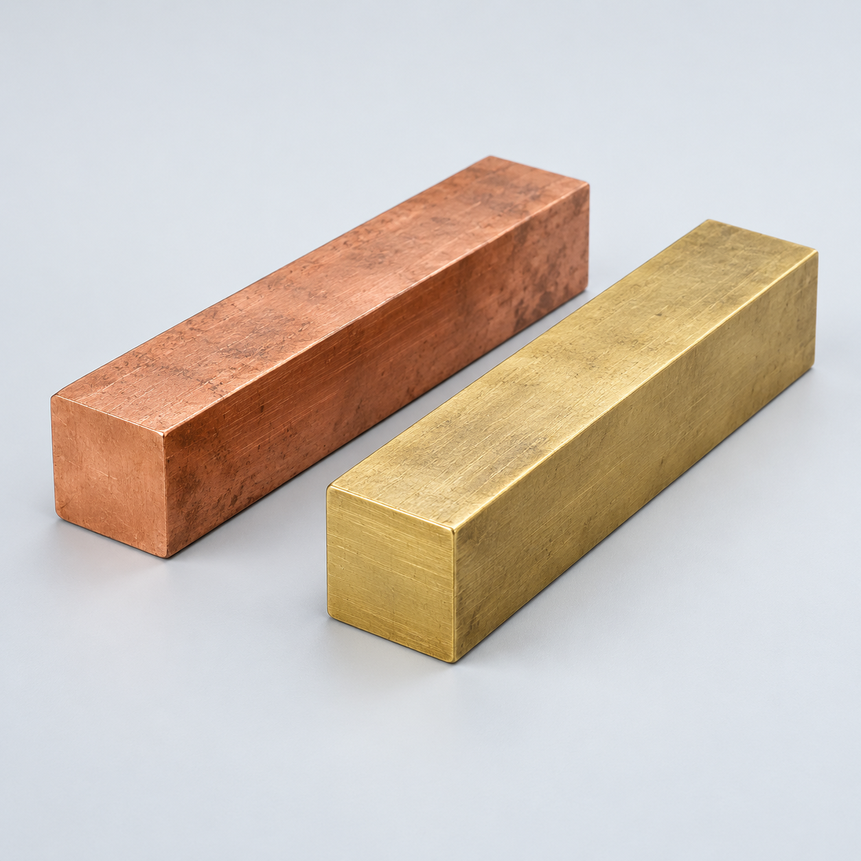 Copper & Brass & BronzeDiscuss conductivity and machining›
Match your polymer to function, process and environment.
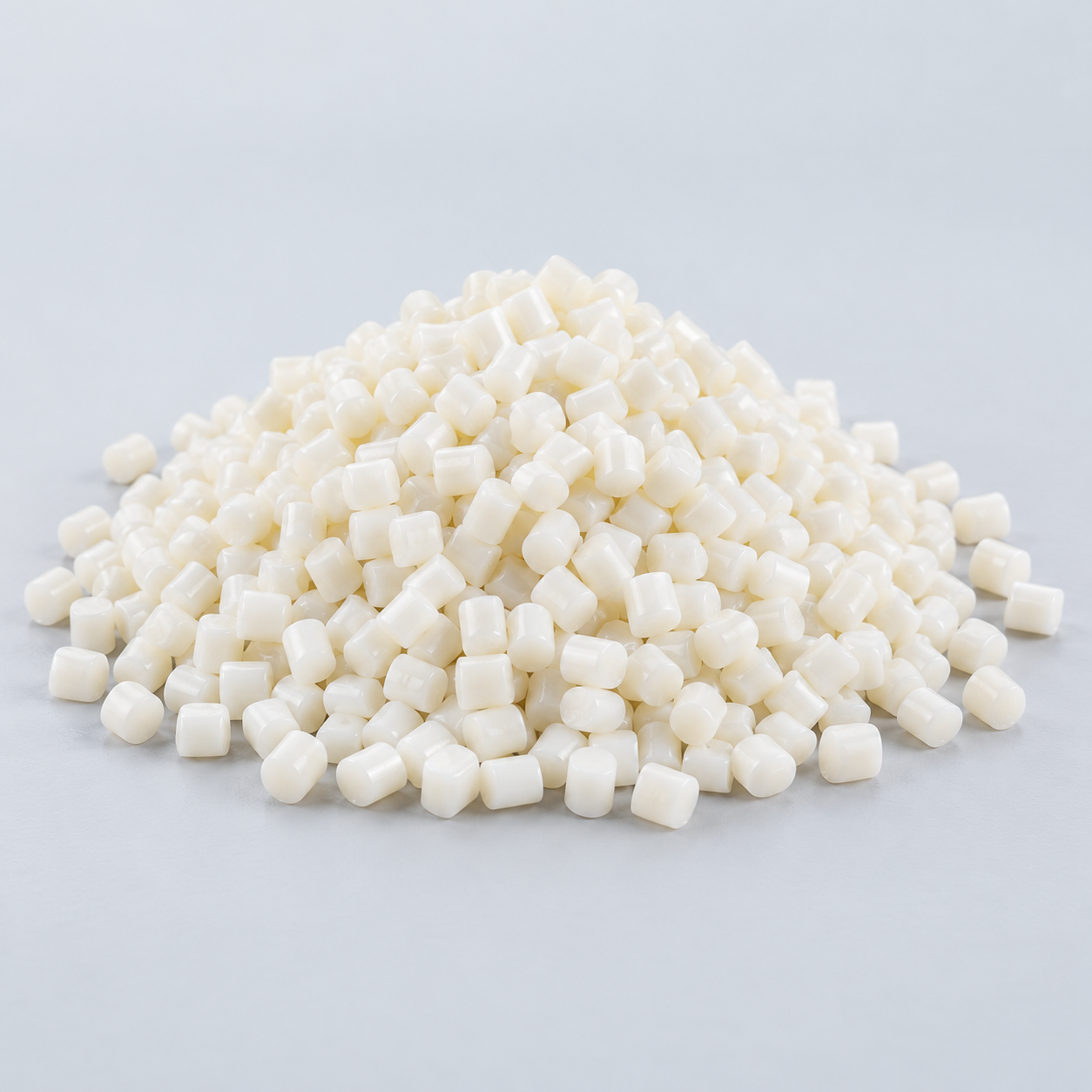 ABSReview enclosure and molding needs›
 Polycarbonate (PC)Discuss clarity and impact needs›
 Nylon (PA)Review moisture and wear conditions›
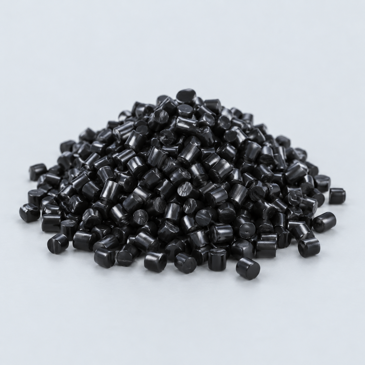 POM / AcetalReview fit and sliding features›
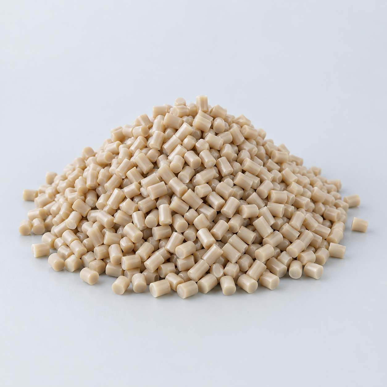 PEEKDiscuss operating conditions›
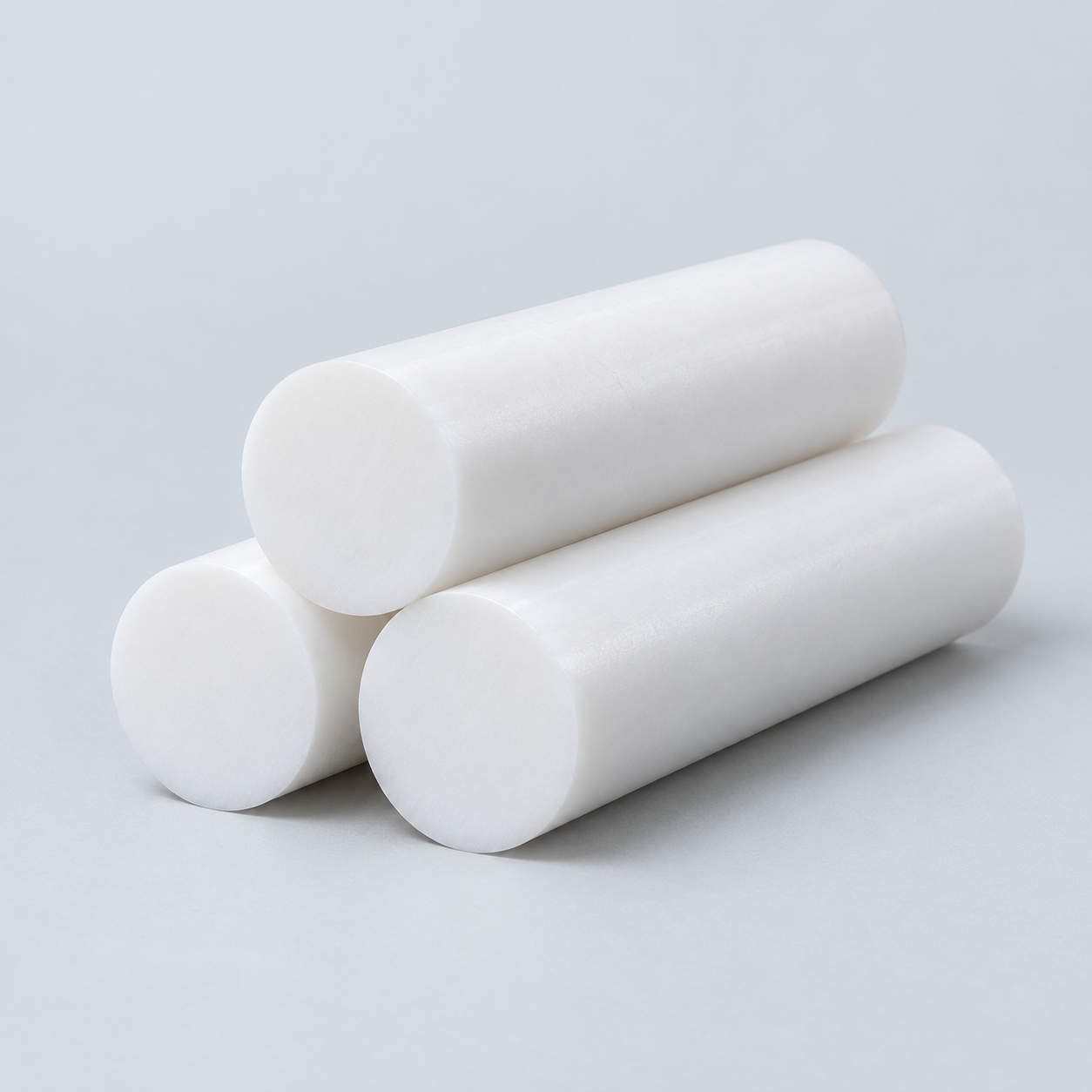 PTFEReview friction and chemical exposure›
 ULTEM / PEIDiscuss thermal and electrical needs›
Confirm grade availability and application requirements.
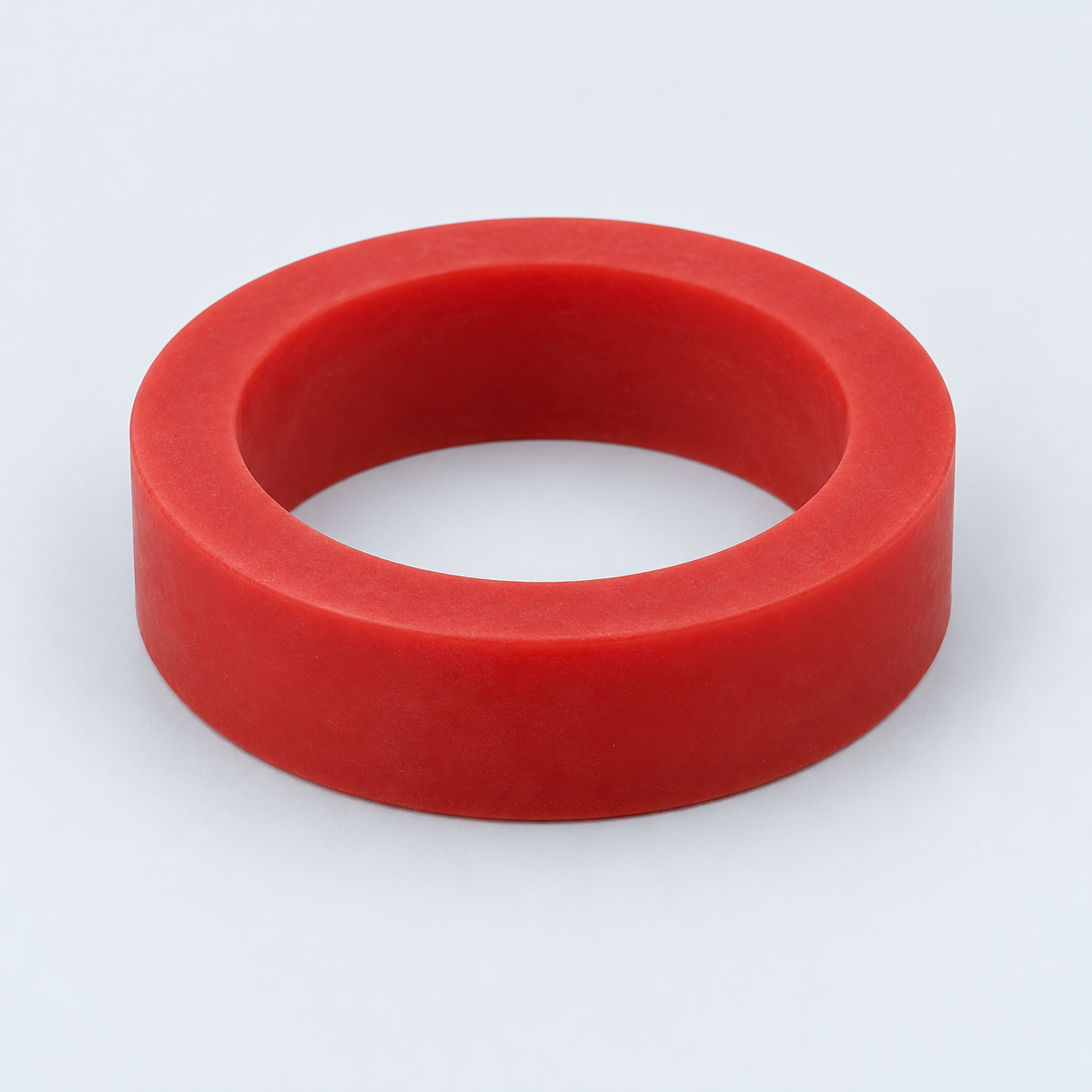 Silicone / LSRDiscuss flexible component needs›
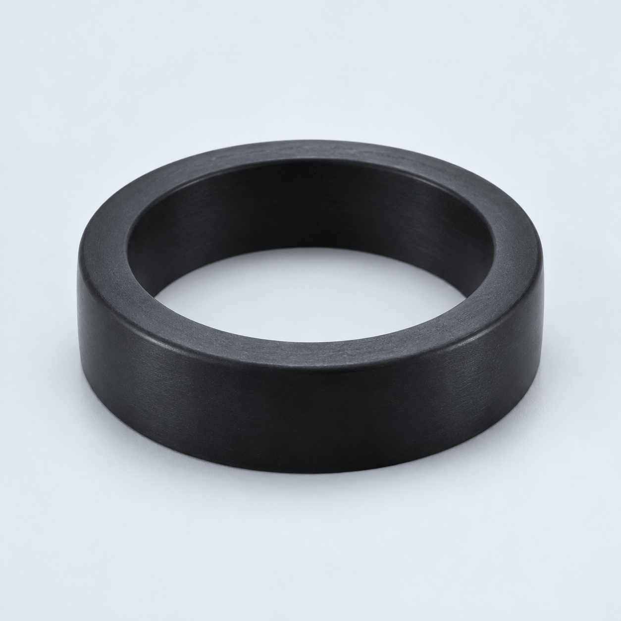 TPU / TPEReview flexibility and processing›
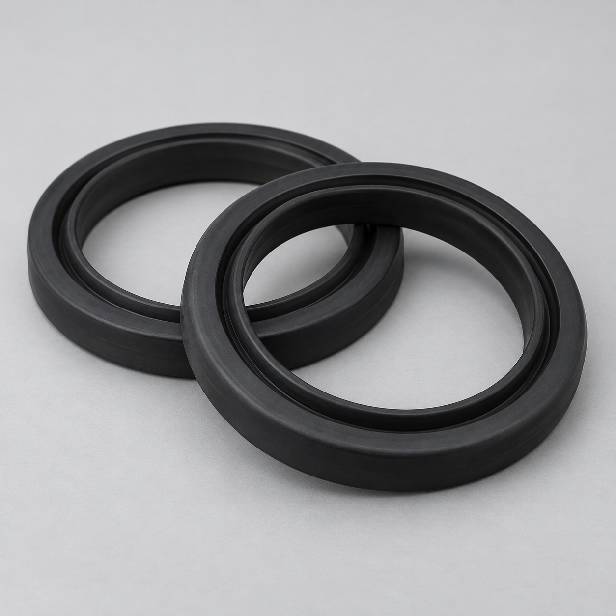 EPDMReview weathering and chemical exposure.›
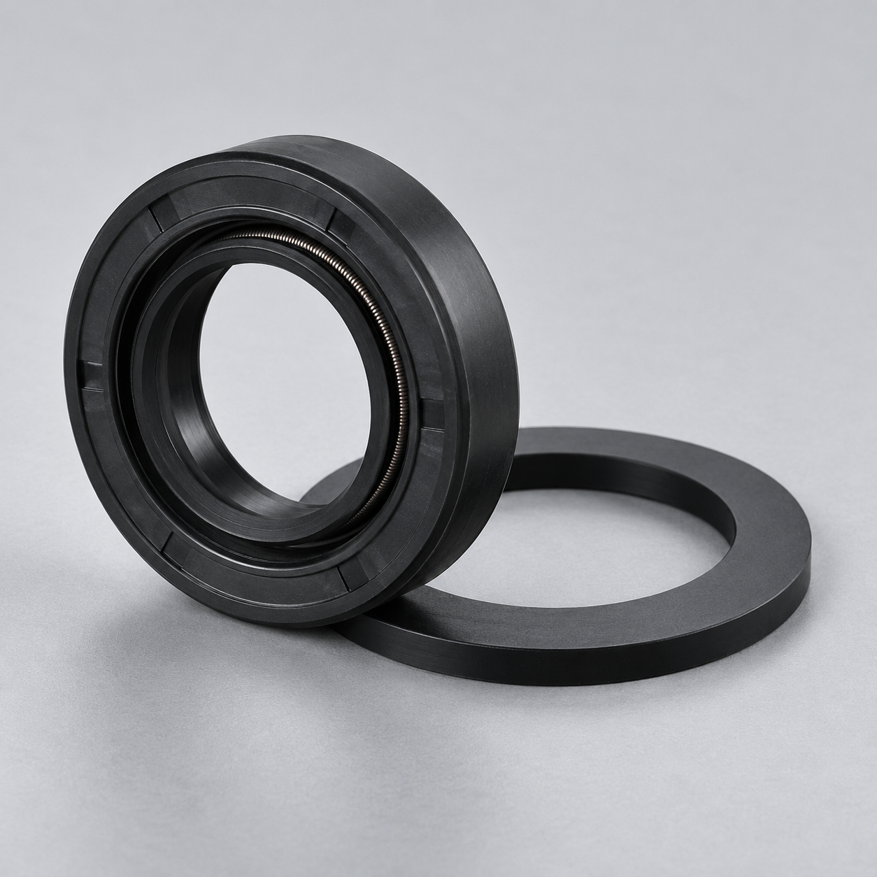 NBRReview oil and fuel exposure.›
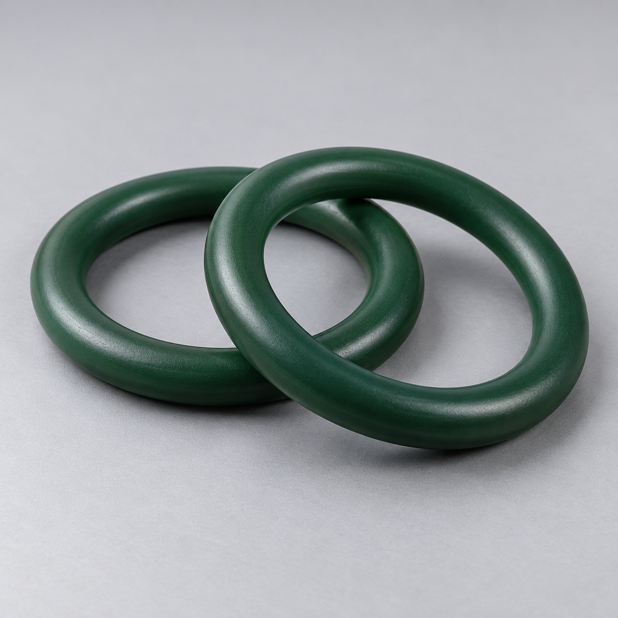 FKMReview temperature and chemical exposure.›
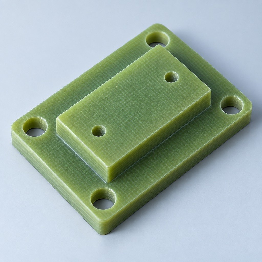 G10 / FR4Review insulation and laminate needs›
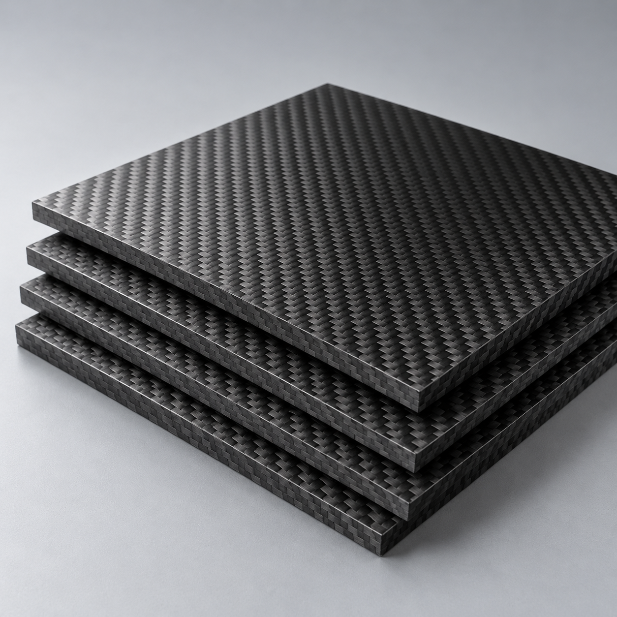 CompositesReview stiffness, weight and laminate.›Customer-Specified MaterialsConfirm your grade and requirements.›Other Specialty MaterialsDiscuss your application and grade.›
Practical guidance for your part geometry and material decisions.
Prepare your process, budget and sourcing questions.
Build your knowledge before production.
Learn who we are and how we operate.
Find our U.S. support team or start a conversation.
CNC TURNING SERVICES
Build your shafts, sleeves and flanges around the fit your assembly needs.
Review your rotational geometry, threads, off-axis features and delivered surface before your prototype or repeat order.
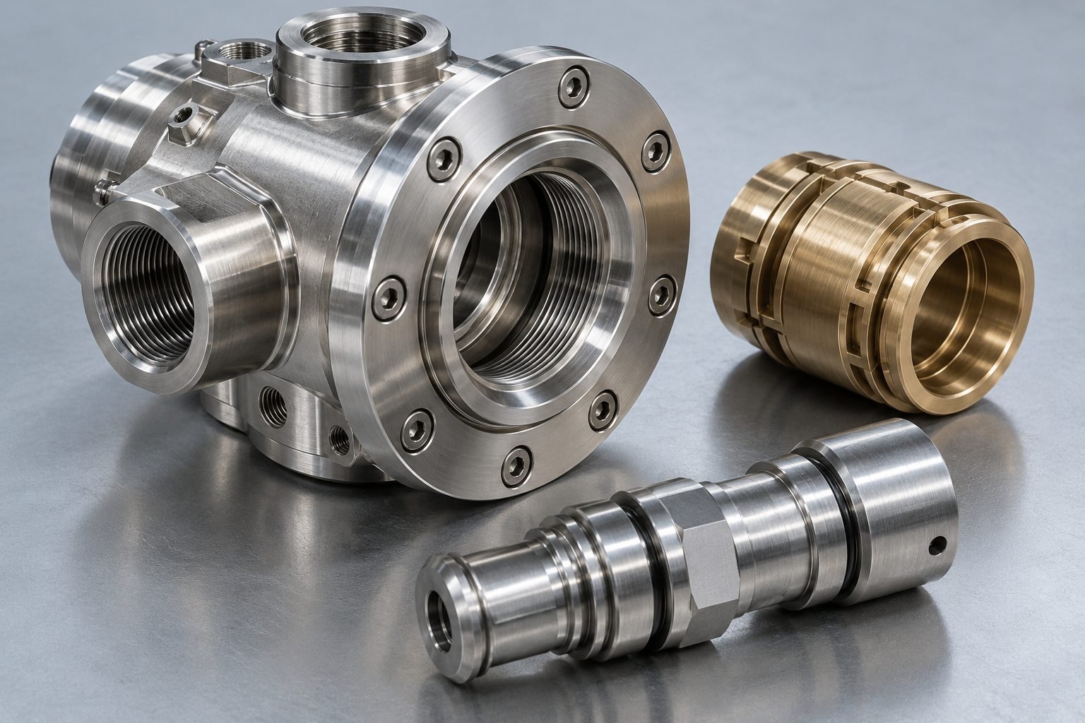
CNC TURNING OVERVIEW
Keep your mating diameters, shoulders and threads working together. Share your CAD and controlled drawing so your process review starts with the features that determine fit and function.
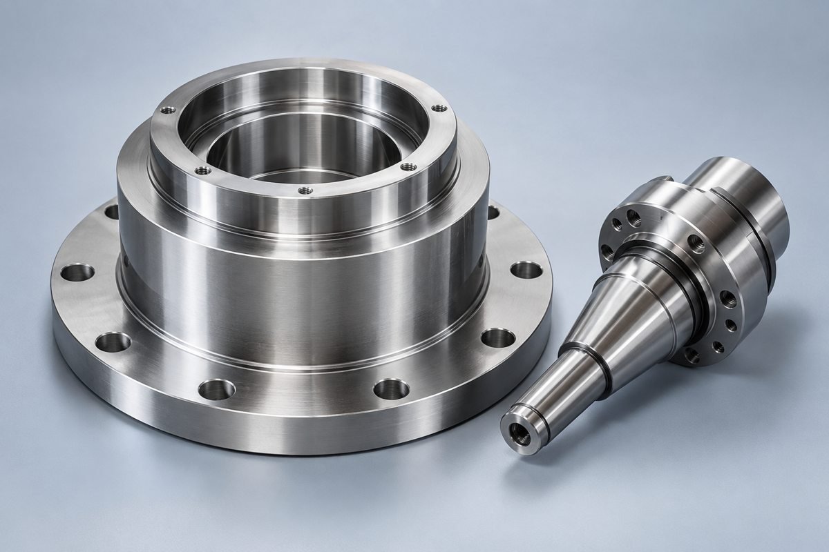
YOUR PROCESS DECISION
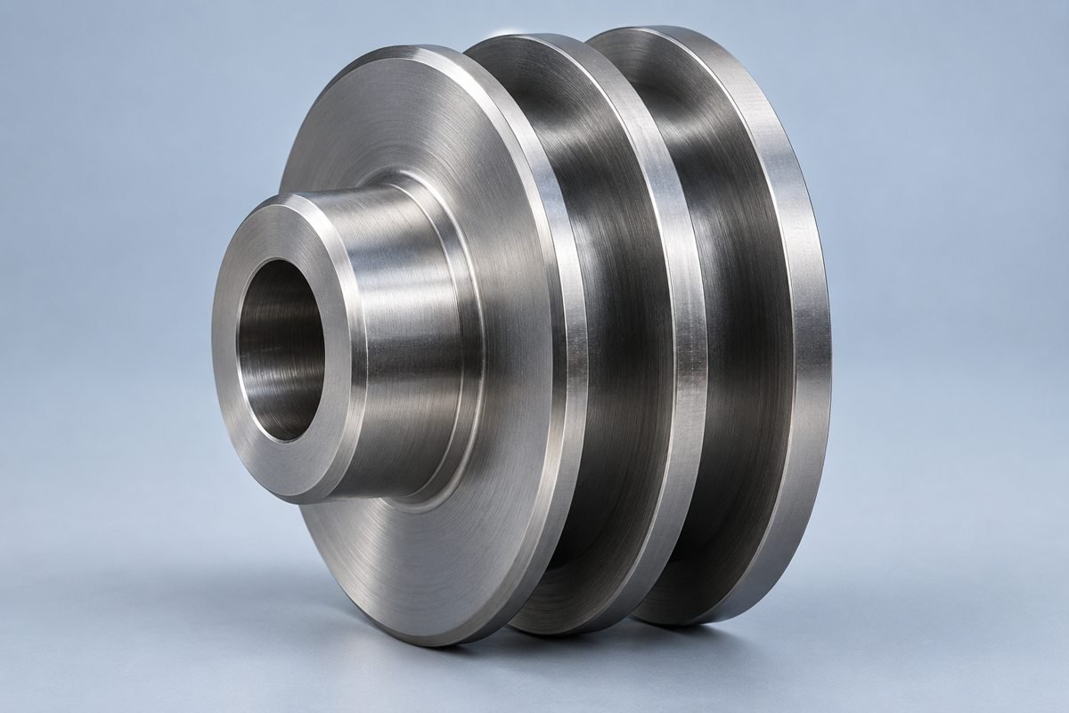
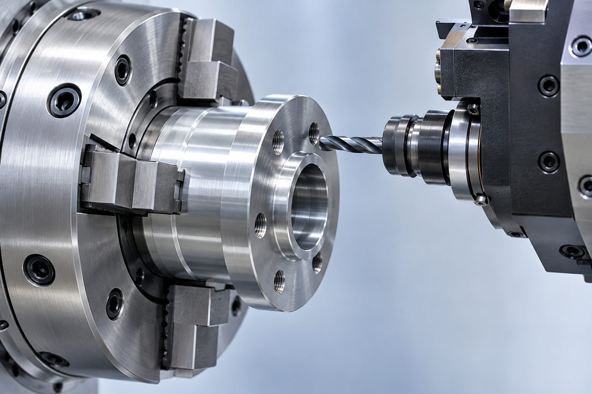
Standard CNC turning: review your cylindrical features and access.
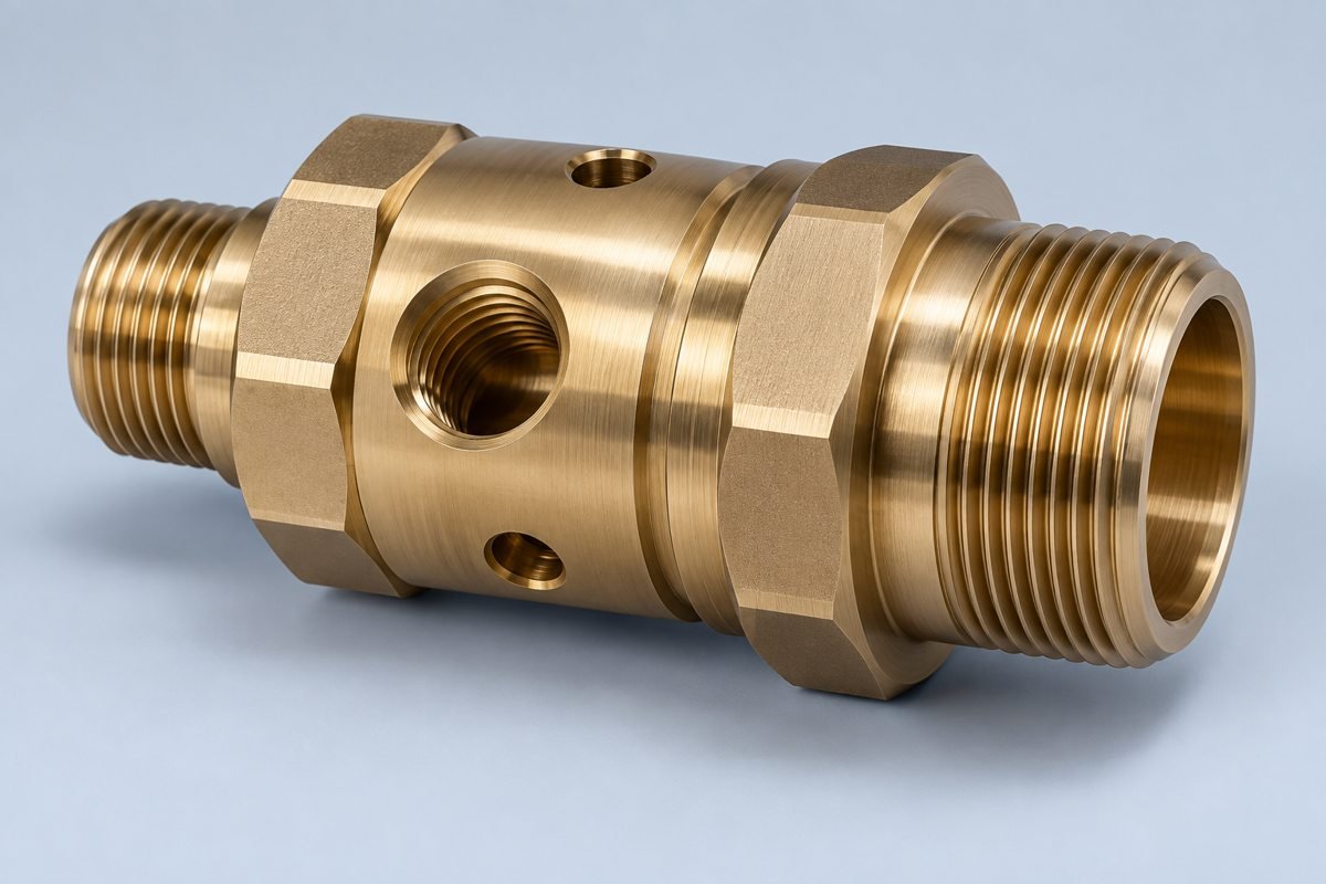
Live tooling: combine off-axis holes, flats and slots where your geometry allows.
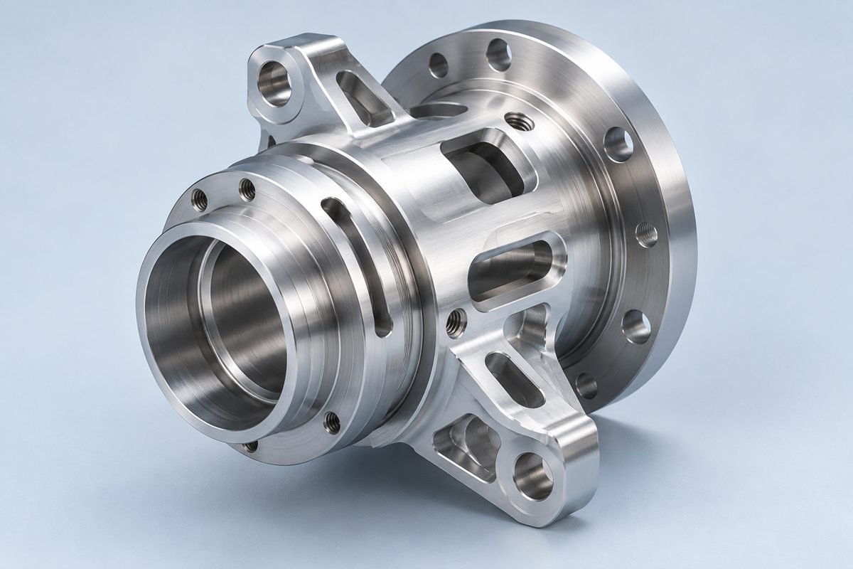
Mill-turn: review turning and milling operations around a shared setup.
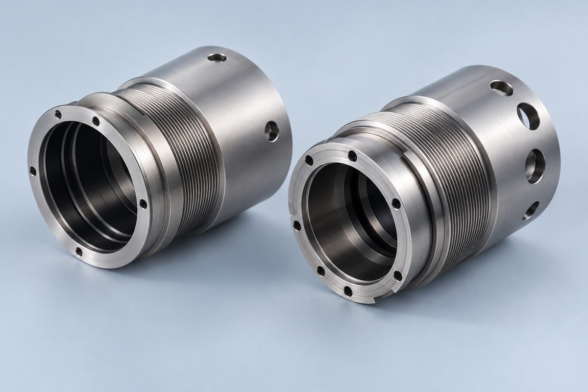
Prototype turning: validate your material, fit and drawing before repeat orders.
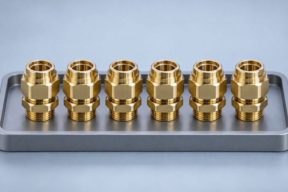
Repeat production: carry your approved revision and inspection scope into each release.
DESIGN FOR MANUFACTURABILITY
Select a topic to review your design before production.
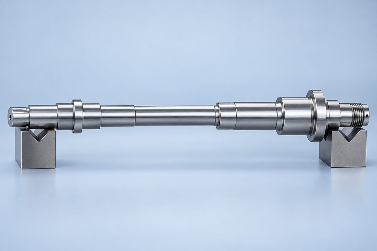
Identify unsupported length and critical diameters. Review tailstock or steady-rest access where your geometry needs support.
Reduce deflection risk for your concentric features.
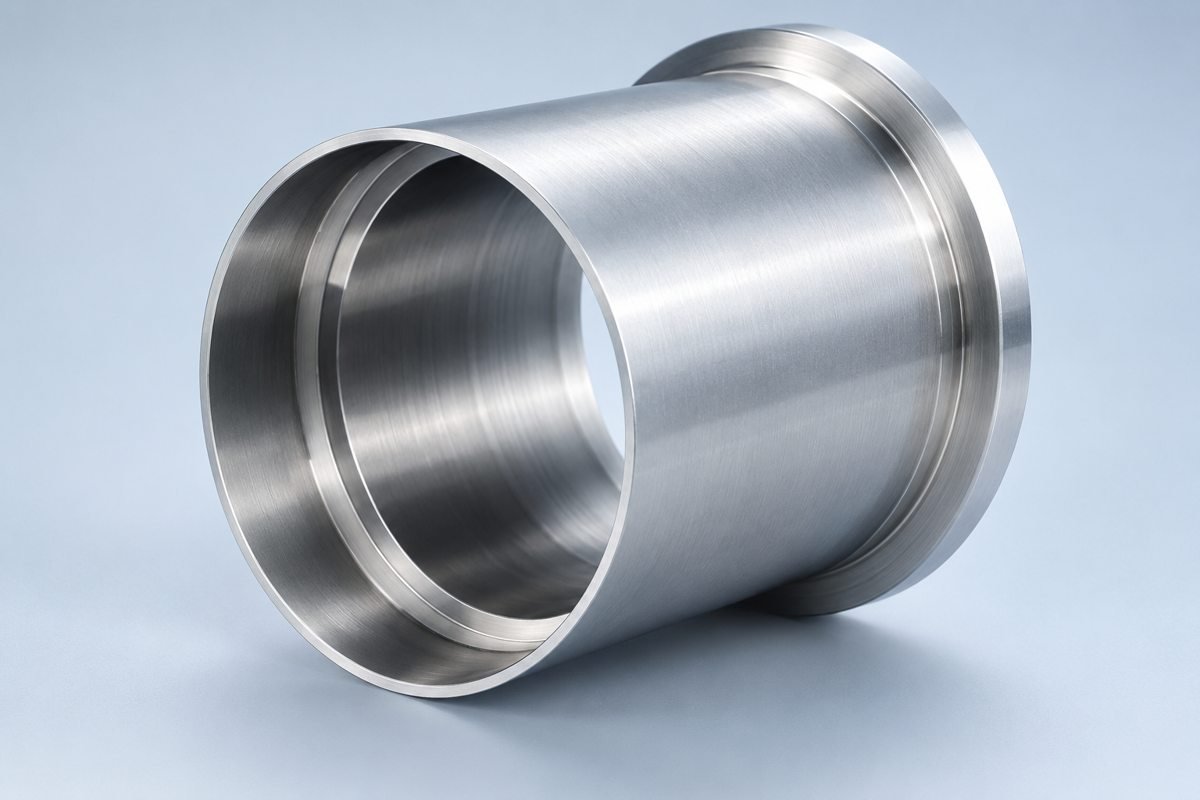
Allow for clamping and cutting forces. Review the machining sequence before final wall thickness is set.
Protect your wall geometry during cutting and clamping.
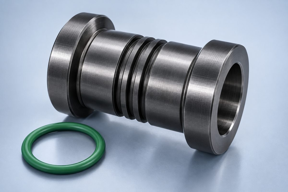
Give the insert clearance and specify functional groove width, depth and edge requirements.
Protect your sealing interface and avoid unnecessary special tooling.
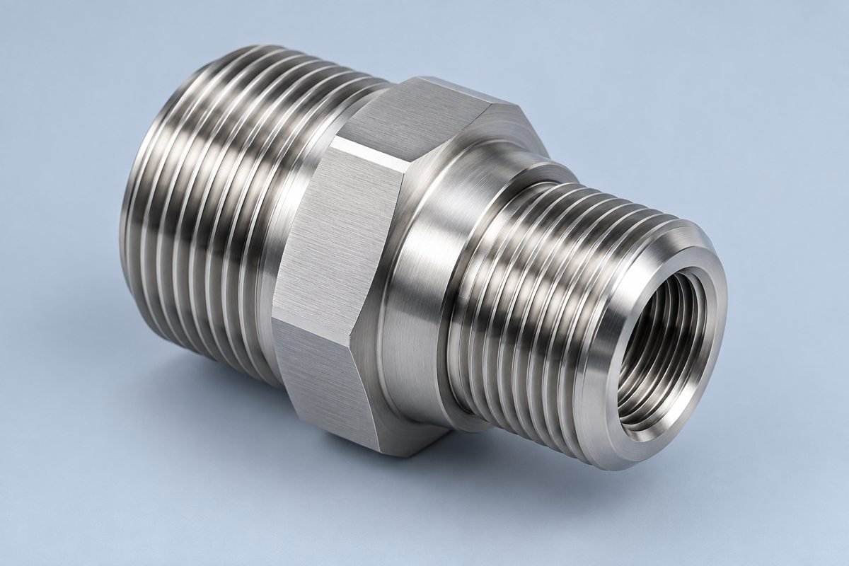
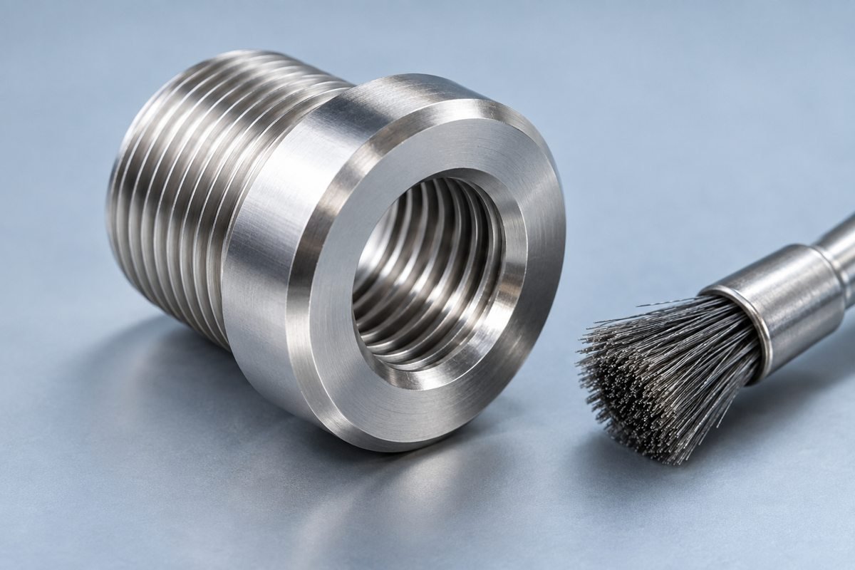
State thread standard, pitch, class and engagement length. Allow tool entry and runout where needed.
Make your mating thread and acceptance criteria clear.
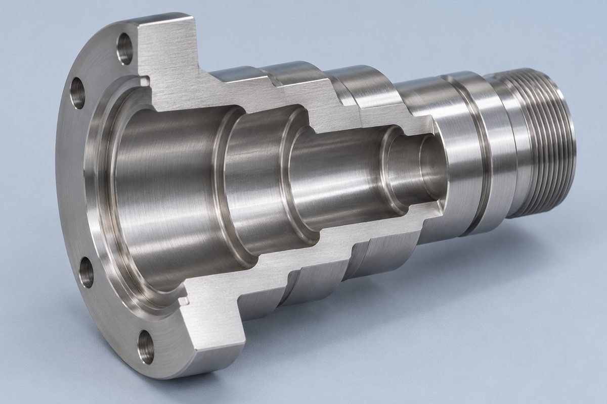
Coordinate shoulder radii with mating parts and practical insert geometry.
Keep your shoulder fit compatible with the machining route.
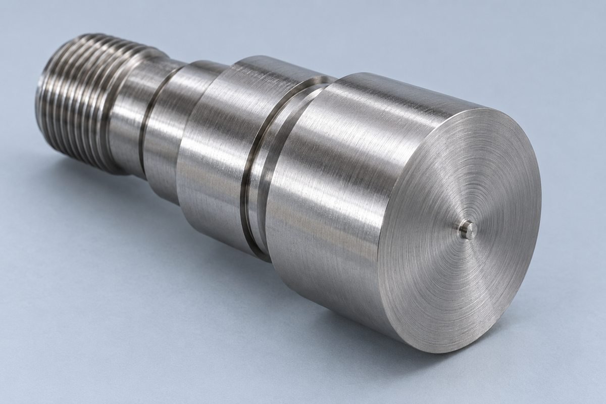
Identify which end face is functional and whether it needs a separate finishing operation.
Avoid unexpected end-face rework on your component.
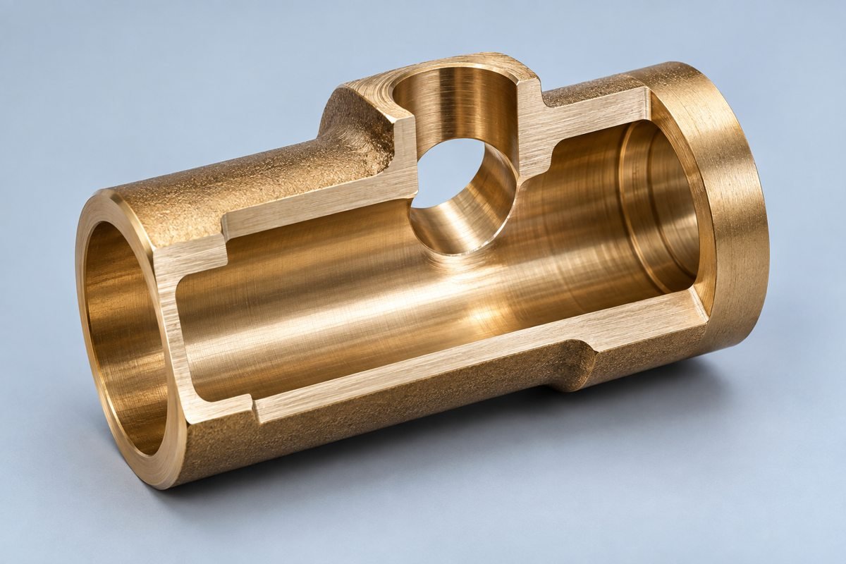
Call out critical edges and intersecting holes. Agree deburring without damaging sealing or mating surfaces.
Remove harmful edges without changing your functional geometry.
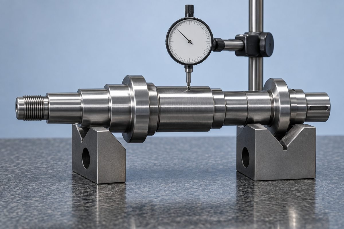
Define your functional datum axis and measurable runout requirements on the drawing.
Connect your measurement setup to the assembly function.
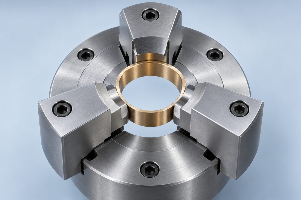
Provide gripping access and review jaw contact on finished or thin-wall surfaces.
Support repeatable positioning without damaging finished surfaces.
PLAN YOUR BUDGET
Extra operations add handling and setup work.
Your grade and condition affect cutting and availability.
Long unsupported features may need added support.
Off-axis features change tooling and programming.
Specify tight control where your function requires it.
Agree masking, coating allowance and delivered texture.
Define measurement methods and report scope.
COMPARE YOUR PROCESS
Compare part diameter, slenderness, support, secondary features and quantity. A guide bushing can support slender stock close to the cutting zone; your complete drawing determines whether that route is suitable.
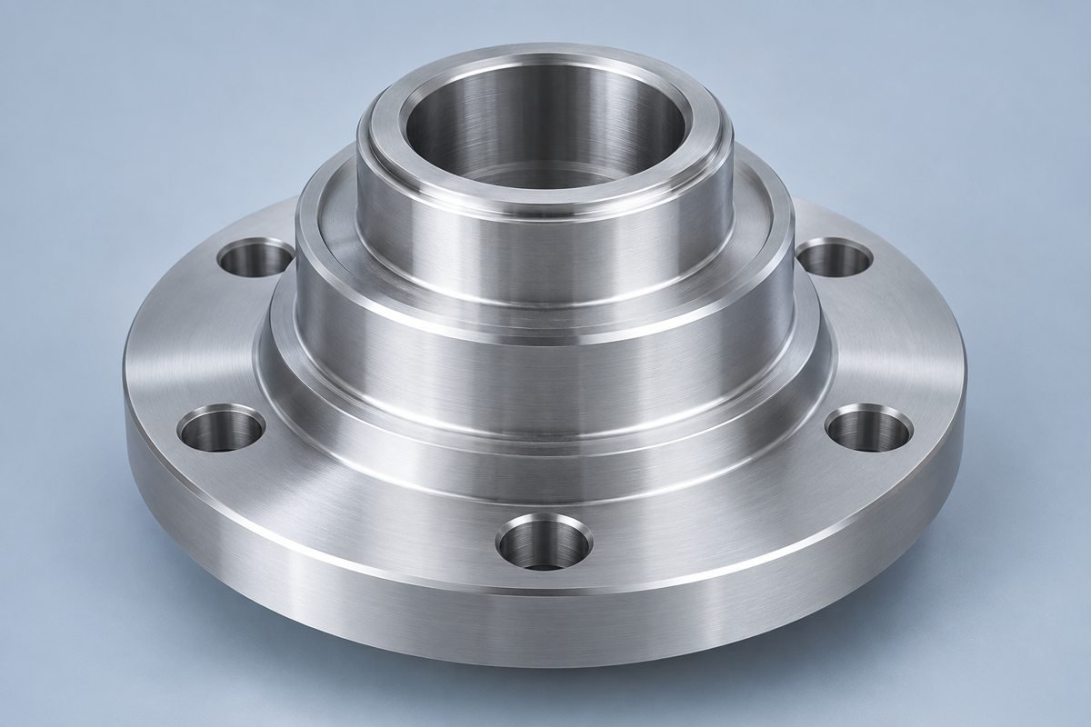
Review your chucking access, rotational features and secondary operations.
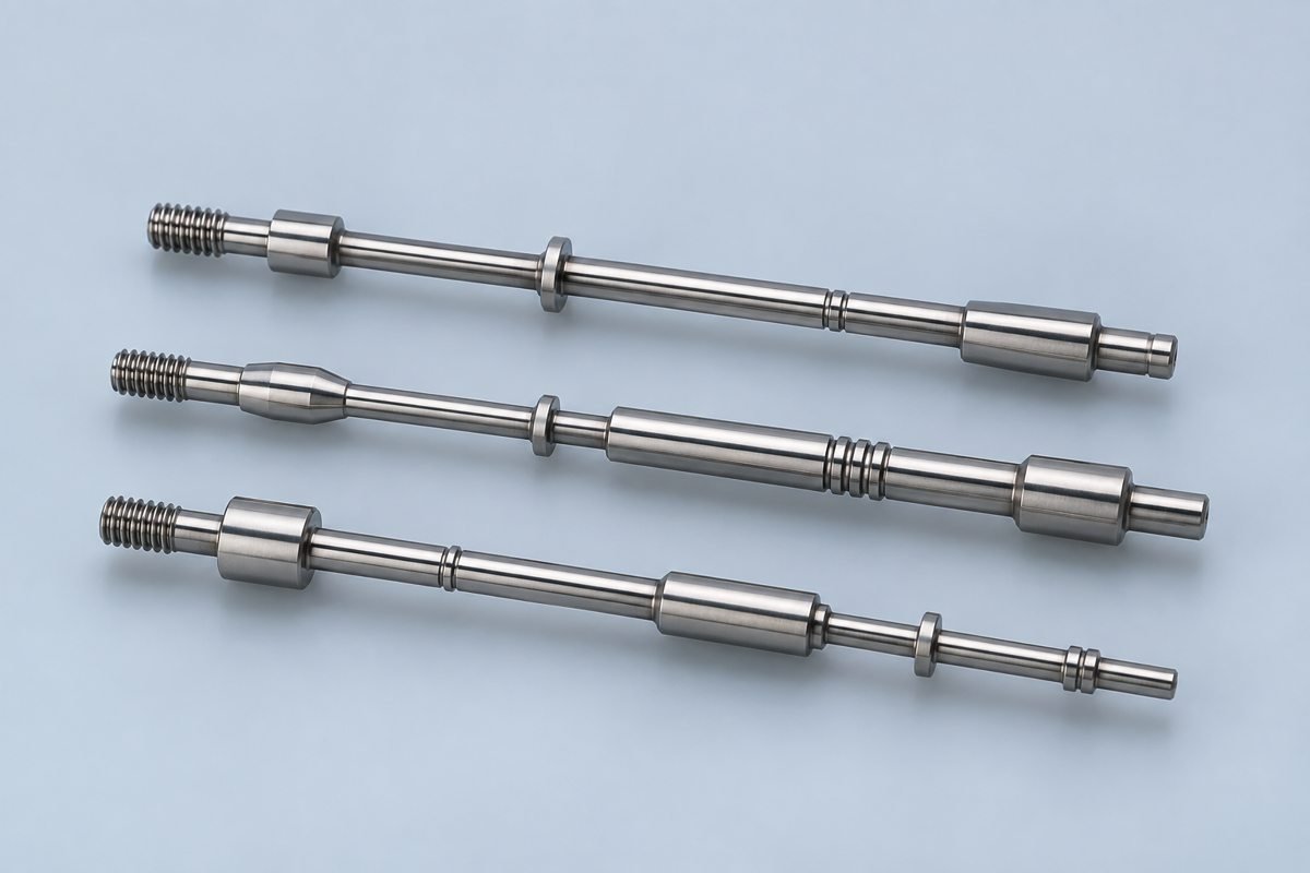
Review slenderness, guide-bushing support and your complete feature set.
COMPARE YOUR OPERATIONS
Confirm process suitability against your complete drawing, rather than choosing by machine type alone.
| Your decision | Standard Turning | Live Tooling | Mill-Turn |
|---|---|---|---|
| Rotational features | Primary process | Turning plus off-axis operations | Combined rotational and milled geometry |
| Off-axis features | Separate operations may be needed | Review tool access and spindle capability | Review the complete machining sequence |
| Setup decision | Compare gripping and datum transfers | May combine compatible operations | May reduce transfers for suitable geometry |
| Your cost review | Stock, cutting time and secondary work | Added programming and tooling | Programming, setup and verification |
MATERIALS & FINISHES
Specify your grade, condition and final finish. Review dimensional allowances, corrosion exposure, wear and any requested material documentation before quotation.
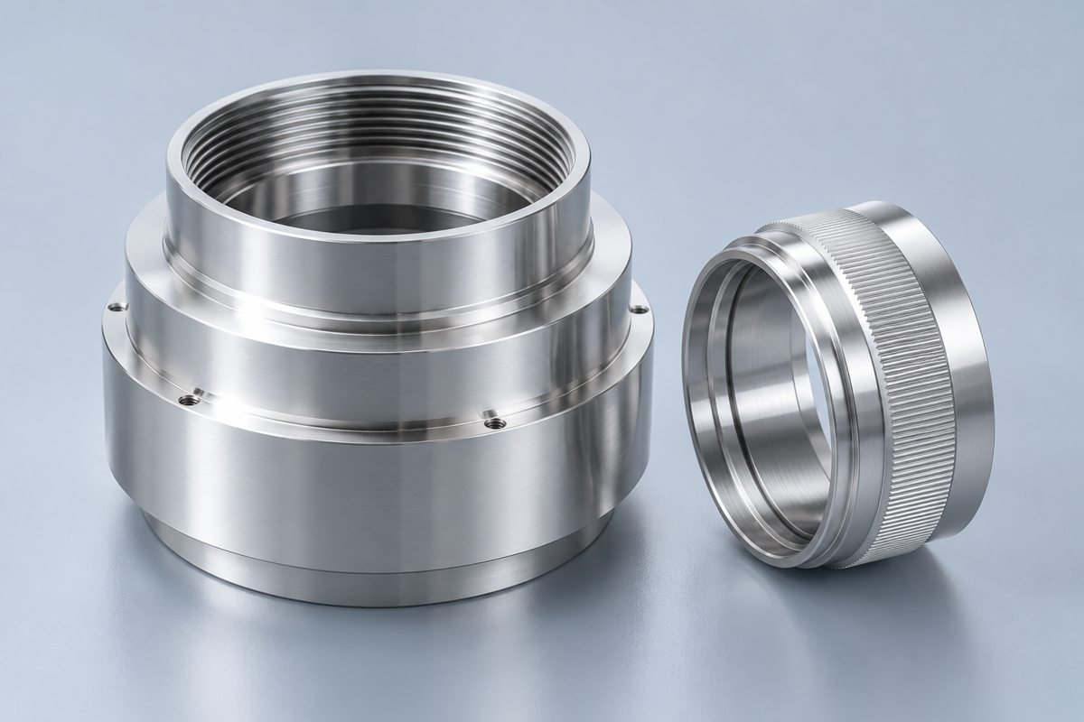
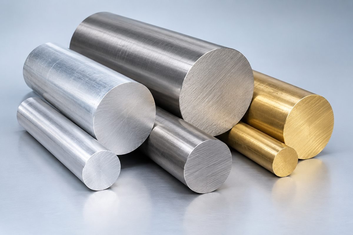
Specify your alloy and temper for lightweight components.
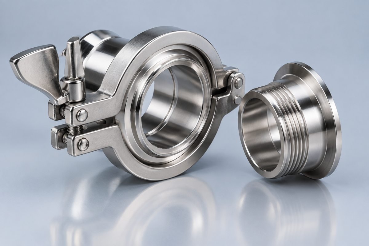
Balance corrosion exposure, strength and machinability.
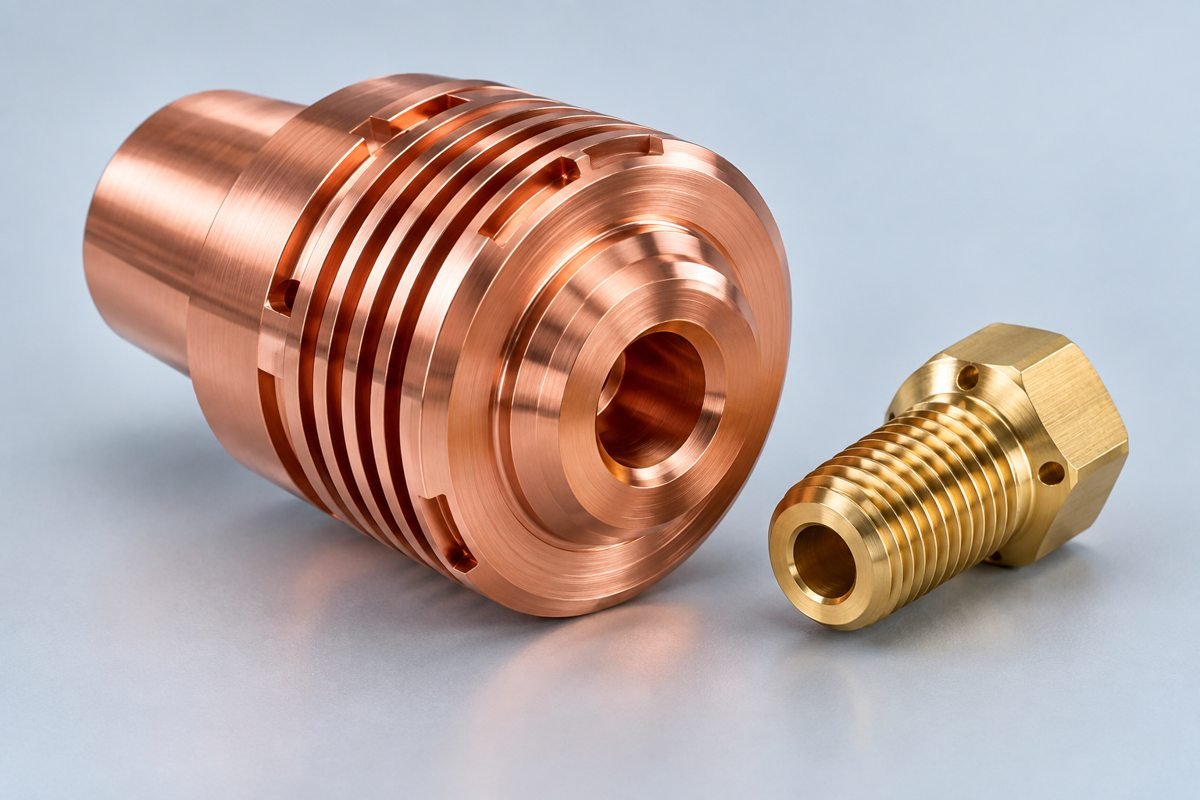
Confirm your alloy for fluid or conductive interfaces.
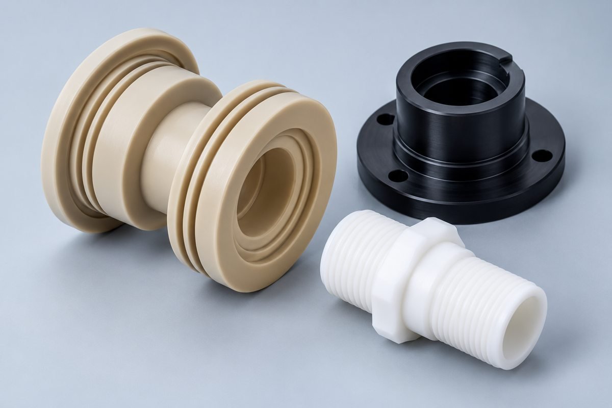
Review temperature, dimensional stability and load.
YOUR APPROVAL PROCESS
YOUR MANUFACTURING SEQUENCE
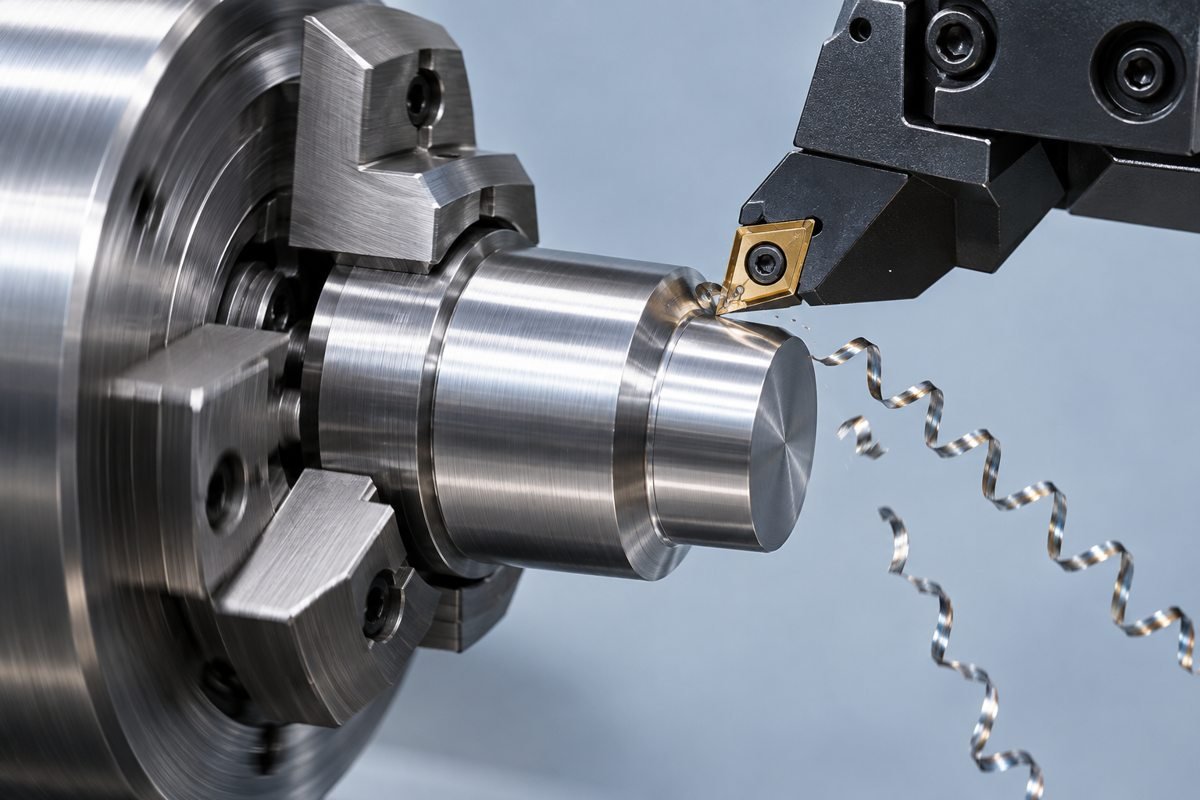
Threading, grooving, deburring and any surface treatment are planned around your drawing.
PRECISION YOU CAN VERIFY
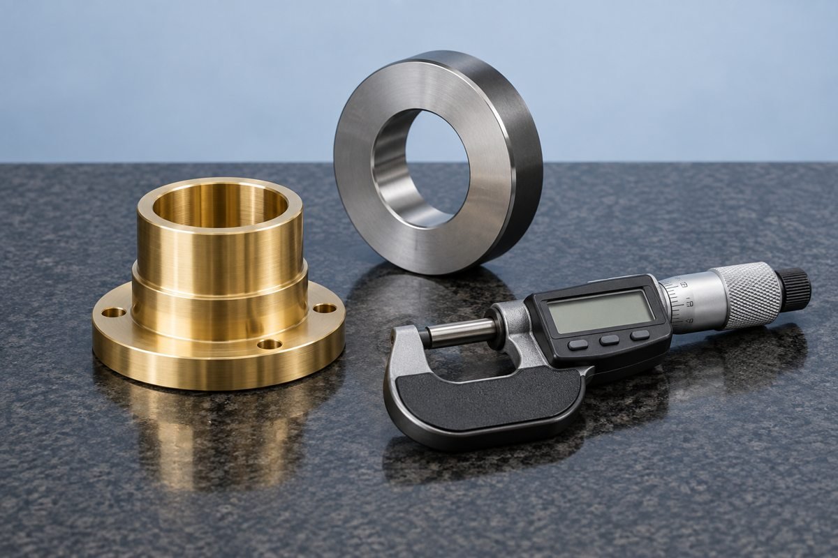
Define your mating diameters, datum relationships, thread acceptance and surface requirements. Confirm measurement methods and report scope for your project rather than relying on a blanket tolerance claim.
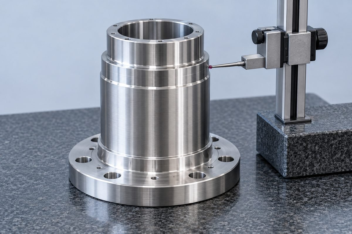
YOUR APPLICATION
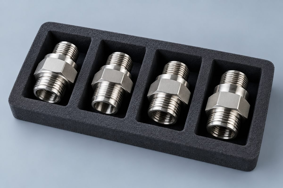
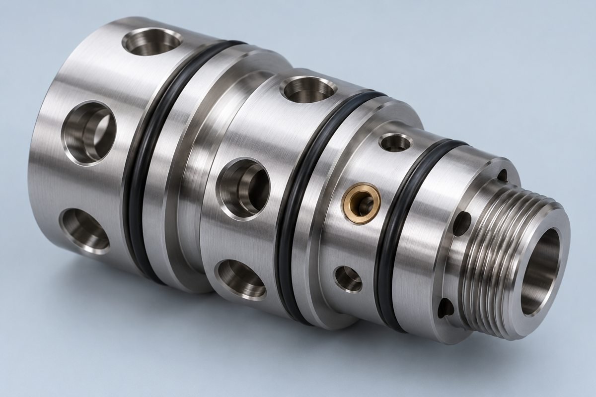
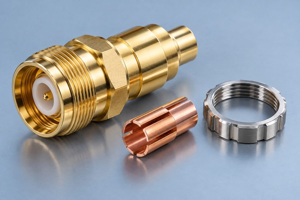
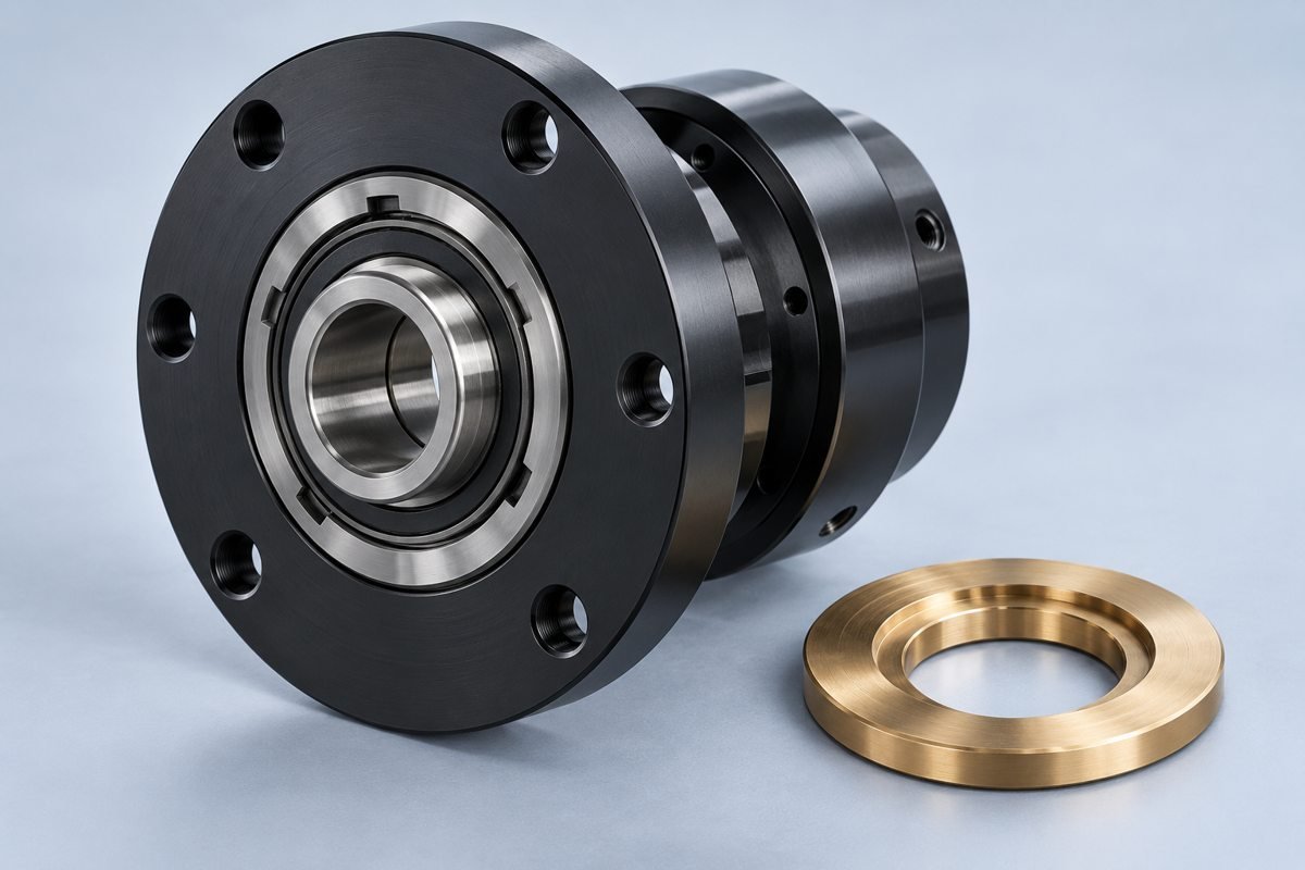
Illustrative applications; project-specific requirements are reviewed before acceptance.
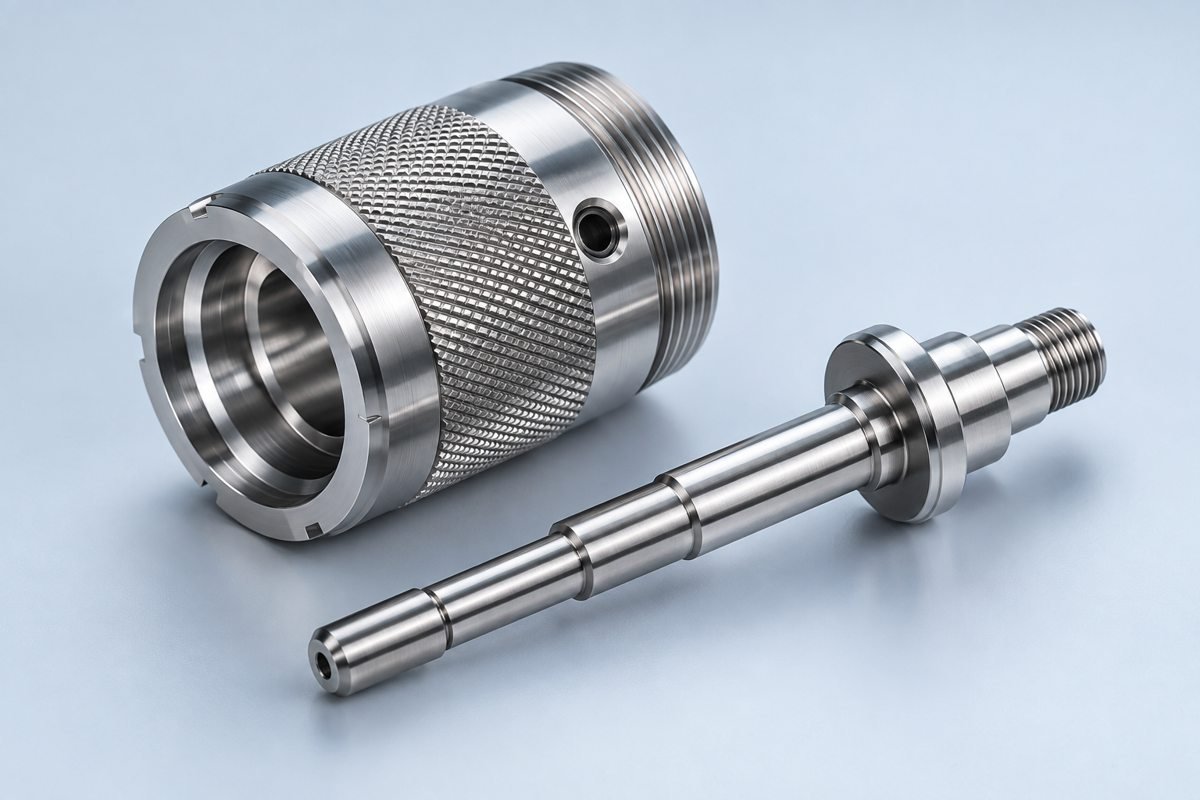
YOUR QUESTIONS
For your CNC turning online quote request, send 6 input groups: CAD and controlled drawing; bar-stock grade; diameters and datum axis; threads and grooves; finish and inspection records; and quantities with delivery needs. Your CNC shaft manufacturer review should use the same finished-part and acceptance scope, rather than comparing unit price alone.
For your CNC threading services review, specify thread standard, pitch, class, engagement length and inspection method. For threaded stainless sleeves, also identify bore-to-thread relationships, sealing faces and cross-hole burr limits. Mark groove width, diameter, edge condition and tool-clearance needs before approving the process plan.
Define your CNC turning runout tolerance against the functional datum axis and identify which surfaces require circular or total runout. Mark mating diameters, measurement locations and the finished condition. For turned flange parts with an inspection report, agree the setup, method and reported features before sample approval; one tolerance does not cover every geometry.
Consider live tooling for off-axis features and Swiss turning for slender supported stock. Your complete geometry, quantity and inspection plan determine suitability.
Share your prototype quantity and anticipated repeat demand. Agree sample acceptance, drawing revision and inspection scope before production release.
Material availability, geometry, setup needs, finishing and inspection affect the schedule. Confirm your delivery target with the quote.
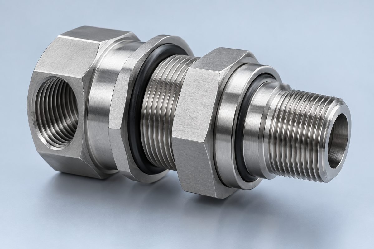
Specify threads, sealing faces and cross-hole edge requirements.
Illustrative geometry, not a customer case study.