Injection Molding
Tooling and molding for your repeat plastic parts.
From prototype to production, coordinated manufacturing solutions for your custom parts.
View All Services →
Precision parts for your tight tolerances and complex geometry.
Tooling and molding for your repeat plastic parts.

Metal casting options for your part and production volume.

Cutting, forming and welding for your fabricated parts.

Custom profiles for your section, length and finish requirements.

Finishes for your appearance, corrosion and wear requirements.

Sub-assemblies and final builds for your production program.

Production tooling built around your process and volume.

Prototype parts to check fit, function and design.
DFM, process planning and production support for your project.
Inspection, documentation, inventory and delivery planning for your program.
Choose air- or liquid-cooling components around your thermal and mechanical requirements.

Manufacturing support for your cold plates, manifolds and cooling assemblies.

Find components for your power electronics, energy, laser and telecom application.

Components for your electronic systems.
Start with your functional and quality requirements.
Build around your operating environment.
From prototype to production, review material performance, manufacturability and cost for your part.
Review grade, temper and finish for your metal parts.
 AluminumStrength, weight and machining›
 Stainless SteelCorrosion and finish requirements›
 Carbon & Alloy SteelDiscuss grade and heat treatment›
 Tool SteelDiscuss tooling and wear needs›
 TitaniumReview grade and part geometry›
 Copper & Brass & BronzeDiscuss conductivity and machining›
Match your polymer to function, process and environment.
 ABSReview enclosure and molding needs›
 Polycarbonate (PC)Discuss clarity and impact needs›
 Nylon (PA)Review moisture and wear conditions›
 POM / AcetalReview fit and sliding features›
 PEEKDiscuss operating conditions›
 PTFEReview friction and chemical exposure›
 ULTEM / PEIDiscuss thermal and electrical needs›
Confirm grade availability and application requirements.
 Silicone / LSRDiscuss flexible component needs›
 TPU / TPEReview flexibility and processing›
 EPDMReview weathering and chemical exposure.›
 NBRReview oil and fuel exposure.›
 FKMReview temperature and chemical exposure.›
 G10 / FR4Review insulation and laminate needs›
 CompositesReview stiffness, weight and laminate.›Customer-Specified MaterialsConfirm your grade and requirements.›Other Specialty MaterialsDiscuss your application and grade.›
Practical guidance for your part geometry and material decisions.
Prepare your process, budget and sourcing questions.
Build your knowledge before production.
Learn who we are and how we operate.
Find our U.S. support team or start a conversation.
Choose your air- or liquid-cooling component around the heat load, available space and assembly interfaces. Review your drawing, joining route and acceptance plan before you order.
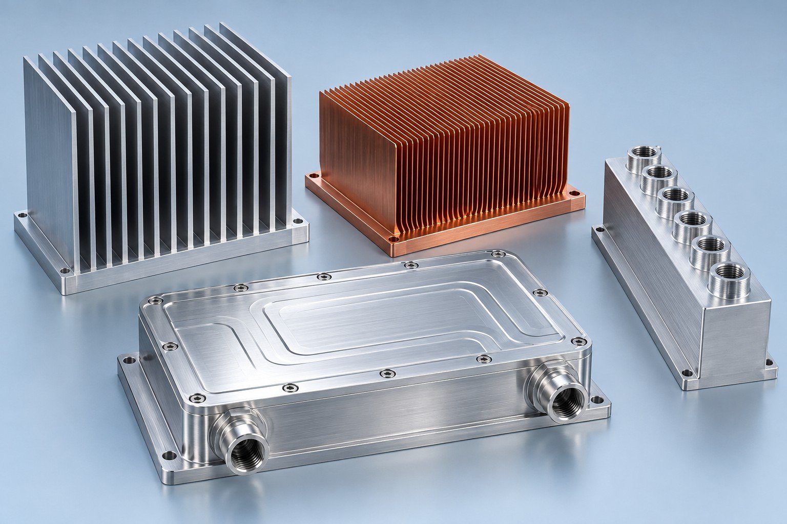
Define your operating point
Match mounting and space
Review the wetted path
Agree checks before release
Start your heat sink and cold plate manufacturing review with the component. Process availability and scope are confirmed for your drawing.
HEAT SINKS
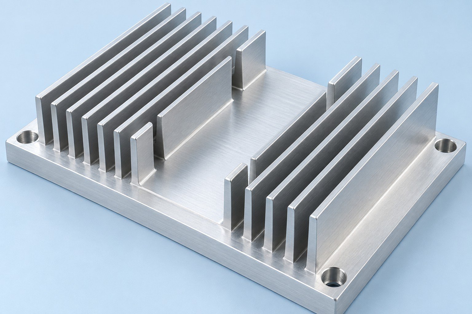
Match your footprint, mounting and airflow.
Review your custom heat sinks around base contact, available fin height and installation clearance. A machined route can suit geometry that differs from a constant extrusion profile. Share the heat map and fan curve before choosing fin spacing.
Review this cooling route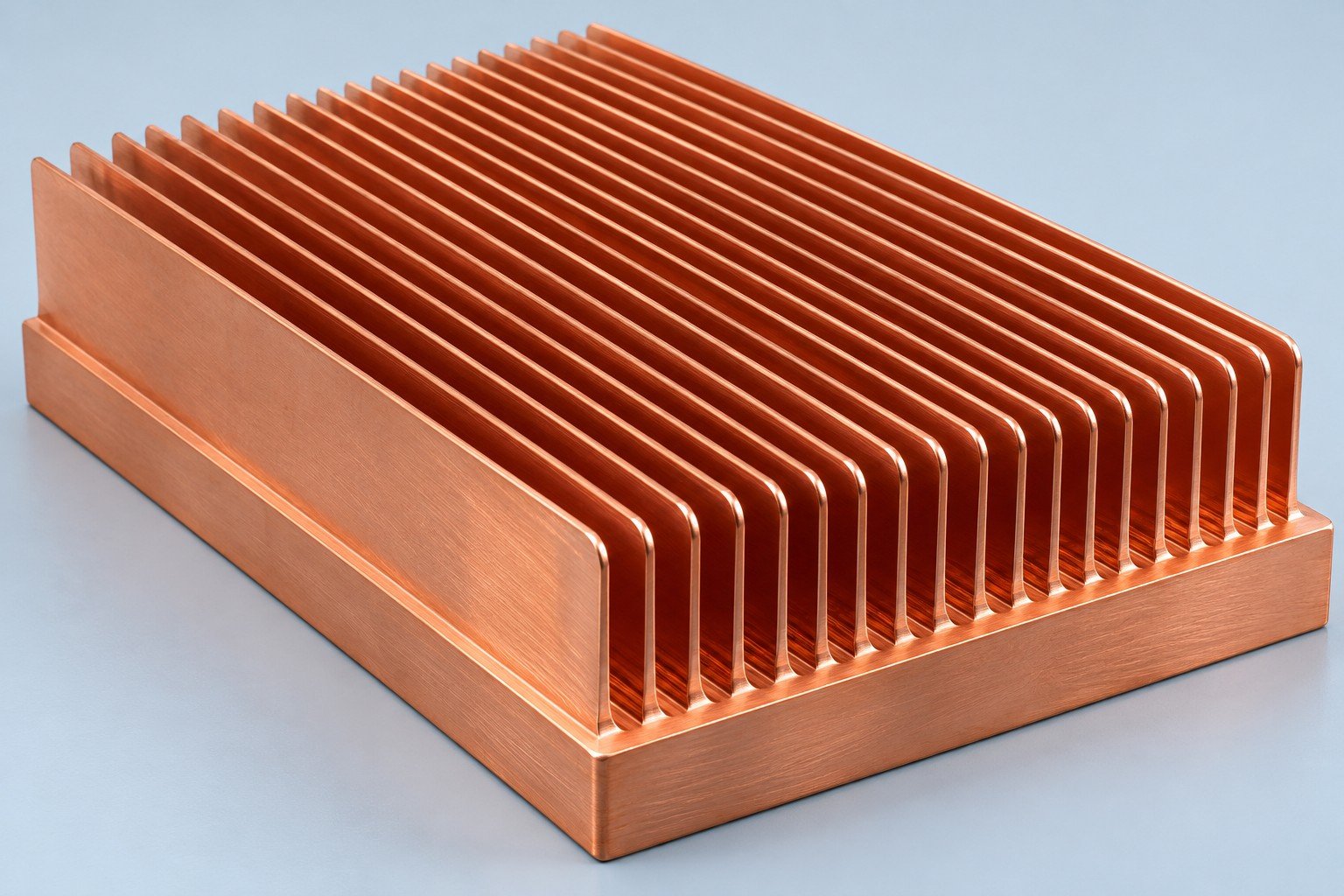
Review fin spacing and integral-base geometry.
For your skived fin heat sinks, review thin-fin geometry, base thickness and the air or liquid path. Dense fins add surface area, but only usable flow through the passages can carry heat away. Material and process availability need drawing review.
Review this cooling route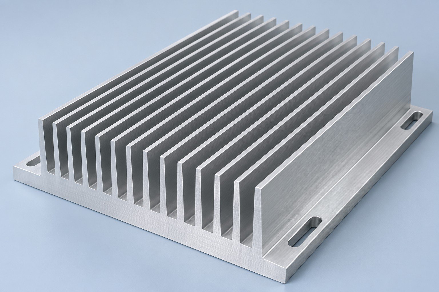
Plan the profile, cut length and machining.
For your extruded heat sinks, confirm the constant cross-section, fin-to-gap proportions, cut length and any secondary drilling or milling. An aluminum extrusion heat sink still needs contact-face and mounting requirements on the drawing.
Review this cooling route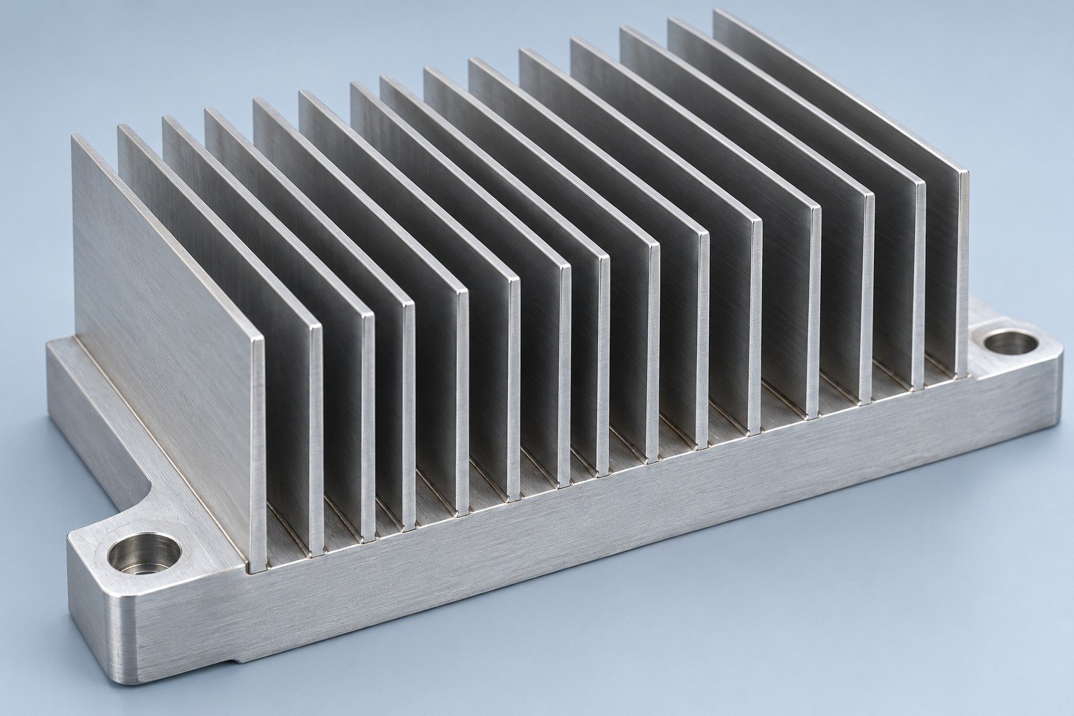
Review the fin-to-base joint and assembly.
Review your bonded fin heat sinks for individual fin alignment, base grooves and joint construction. The fin attachment method affects the inspection plan; do not assume an adhesive-bonded joint and a brazed joint have the same limits.
Review this cooling routeLIQUID COOLING
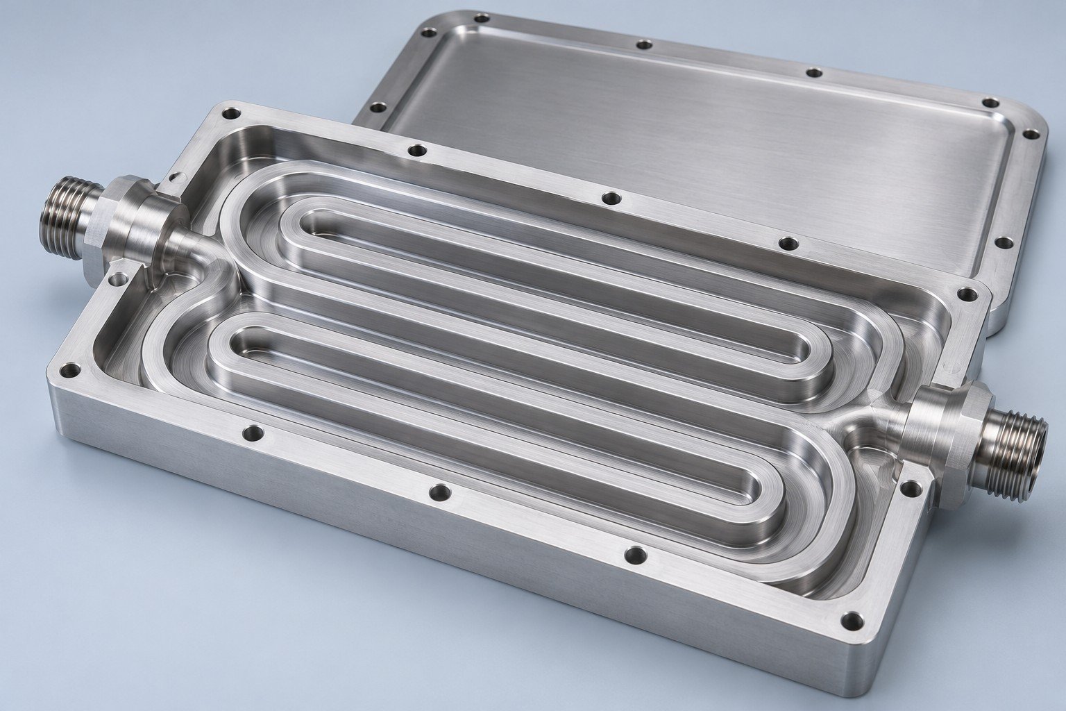
Define channels, ports and contact faces.
For your custom liquid cold plates, specify the heat source locations, coolant, inlet temperature, flow range and allowed pressure drop. Liquid cold plate manufacturing also needs a defined cover joint, sealing surfaces and leak-test acceptance.
Review this cooling route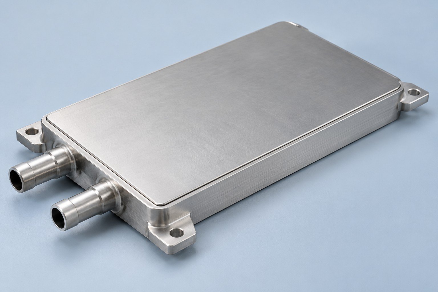
Review enclosed passages and joint access.
Review your vacuum brazed cold plates around the alloy combination, internal passage support and braze-joint design. Confirm cleaning, inspection access and the agreed leak-test method before the sample build; joint qualification is project specific.
Review this cooling route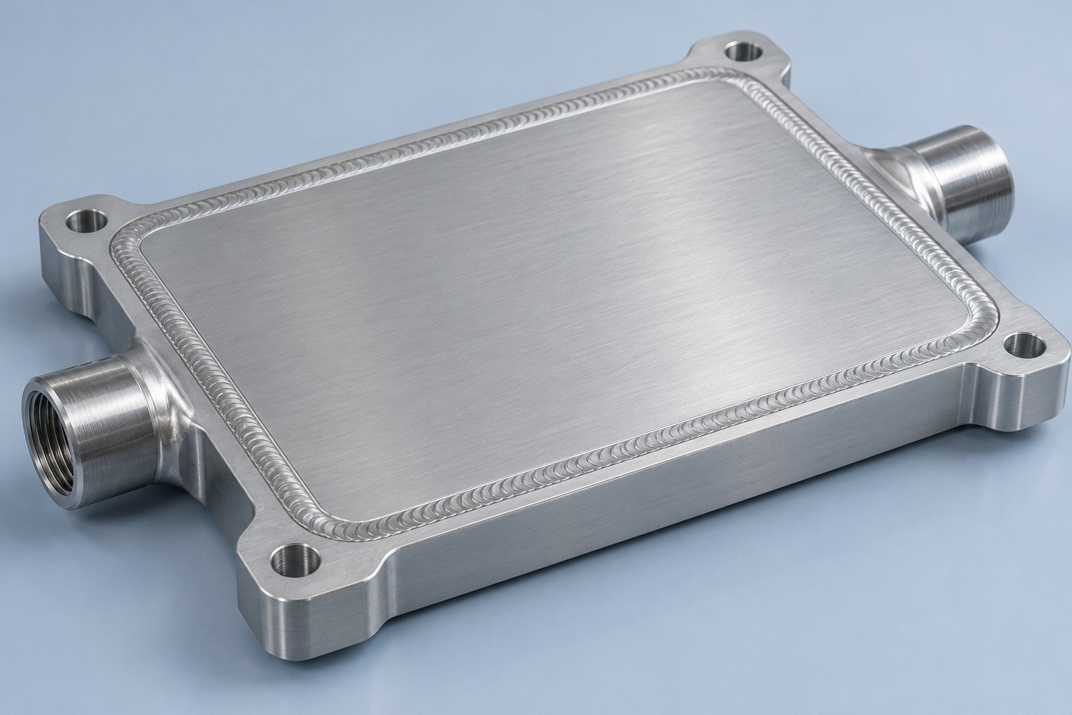
Confirm the cover joint and tool access.
For your FSW cold plates, review compatible alloys, cover thickness, joint support and friction stir tool access. Keep ports and mounting features clear of the tool path. Define final flatness and the agreed post-joining checks.
Review this cooling route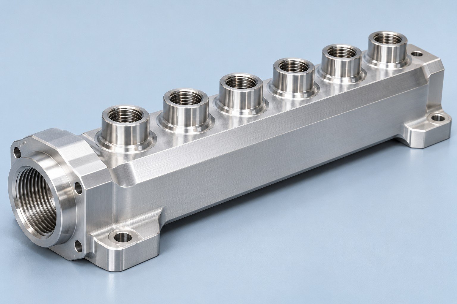
Match flow paths, ports and sealing faces.
For your custom cooling manifolds, confirm branch flow needs, thread standards, O-ring seats and fitting access. Supply the mating connector specification: a nominal port diameter alone does not define a seal or an interchangeable connection.
Review this cooling routeUse your operating conditions to compare manufacturable components; system thermal validation is a separate scope.
Review aluminum or copper, the fin route and any fin-to-base joint; confirm process availability for your geometry.
Compare aluminum and copperThermal acceptance needs the specified heat input, airflow, ambient conditions and interface assembly. Dimensional checks alone do not establish cooling performance.
See sample and release records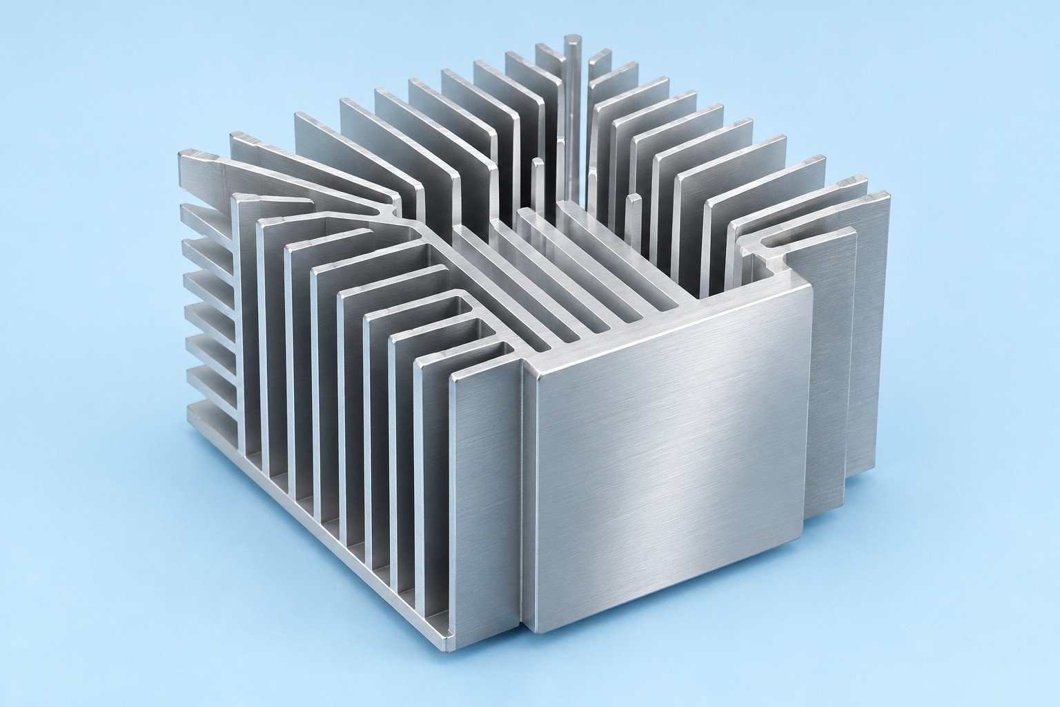
Review coolant compatibility with every wetted metal, the cover joint and cleanable passage geometry.
Compare aluminum and copperAgree test fluid, pressure, hold time, leakage limit and report scope. Thermal tests need the stated flow, inlet temperature and heat input.
See sample and release records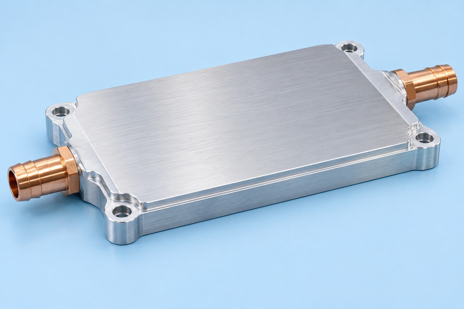
Match all wetted metals, port finishes and seals to the coolant; specify any dissimilar-metal isolation.
Compare aluminum and copperAgree leak / pressure checks, branch identification and cleanliness evidence. Flow distribution is verified only when included in the agreed test scope.
See sample and release records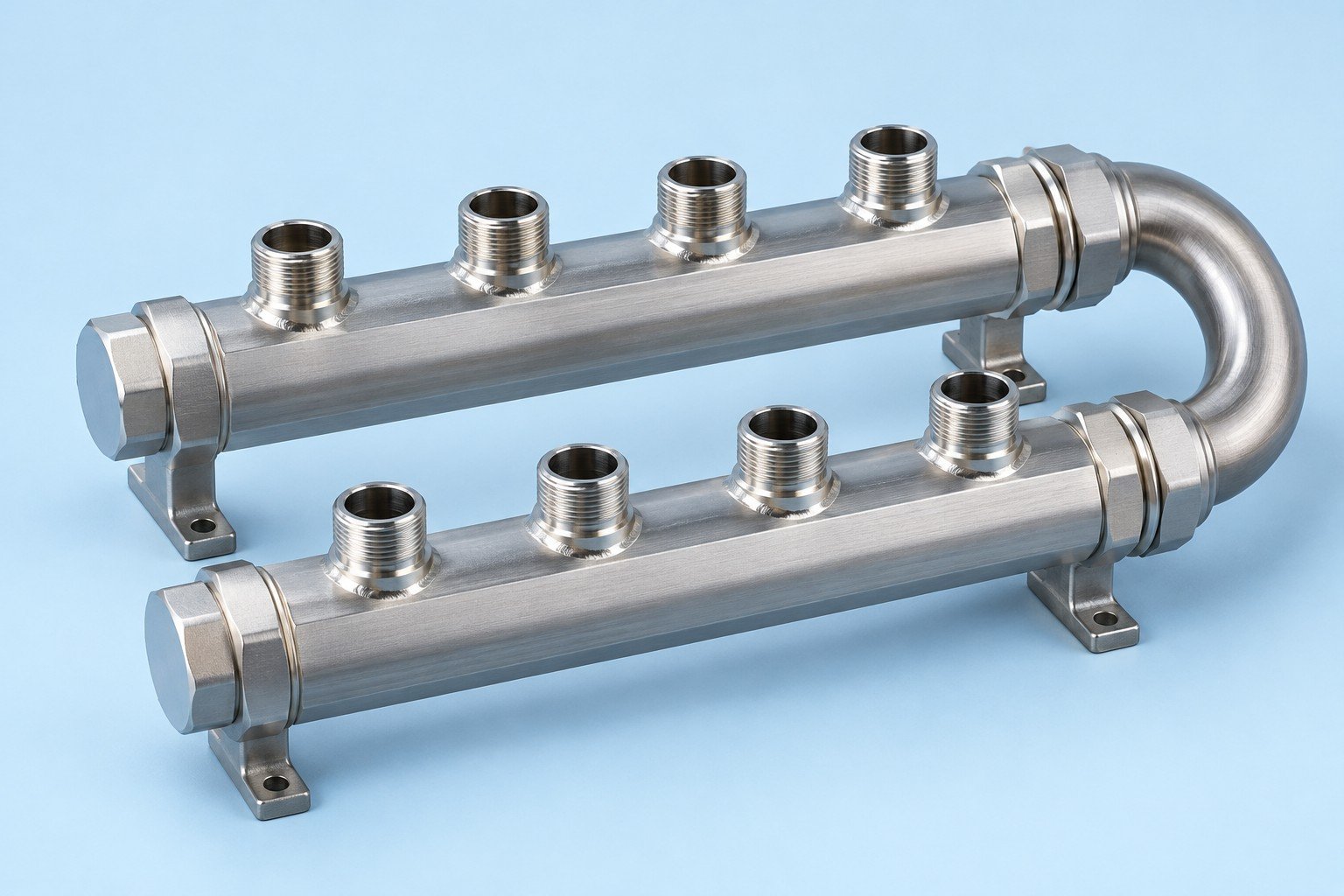
Give your reviewer the operating point, not only the outside dimensions.
Airflow at the installed part matters more than an unrestricted fan rating.
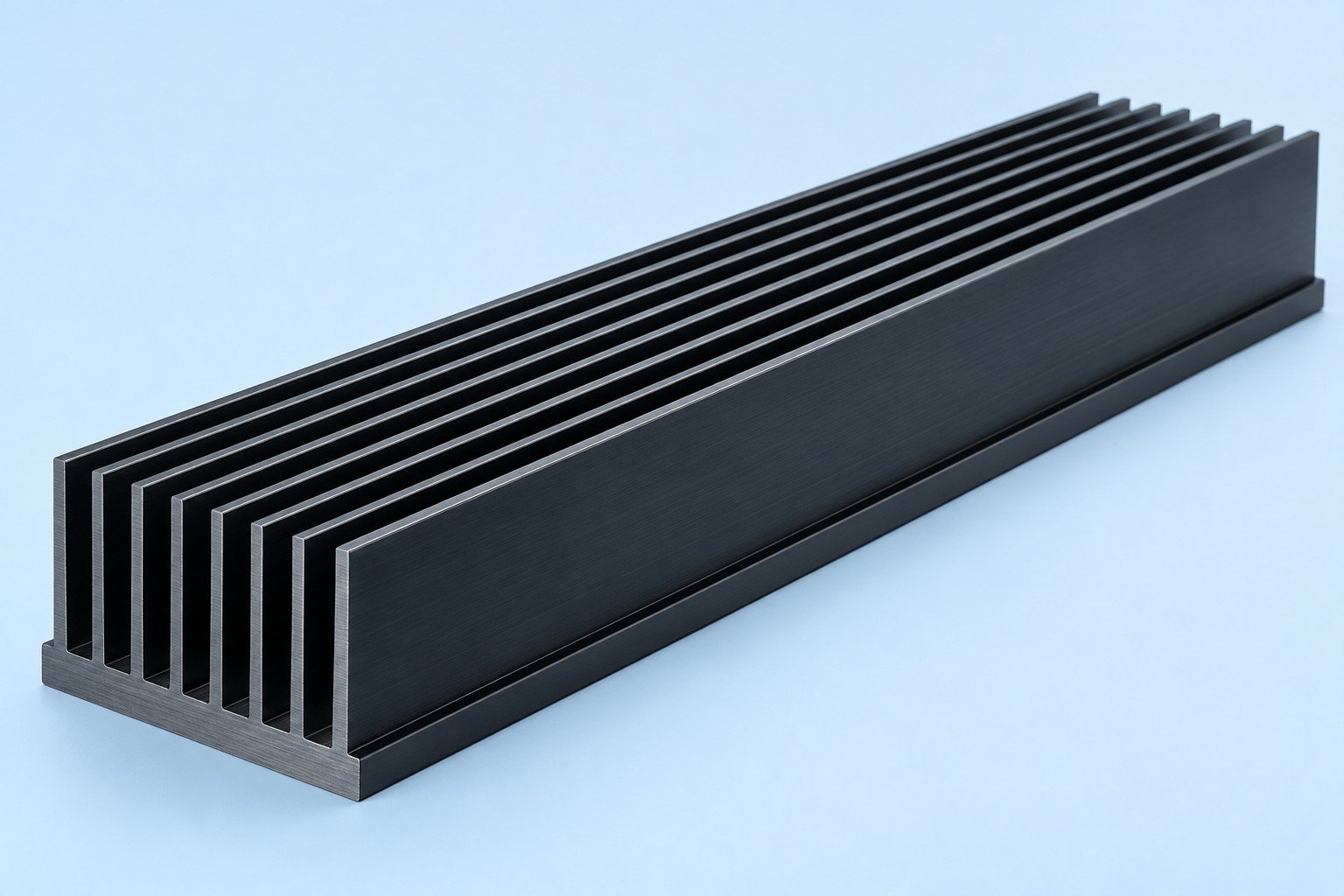
Include the complete wetted path when you review materials and coolant.
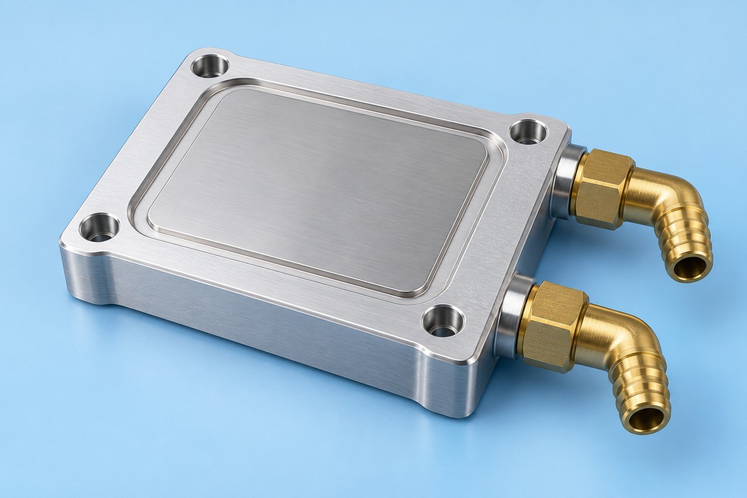
For your cold plate, conductivity is one input. Weight, wetted-path compatibility and the joining route also affect your choice.
C110 copper offers higher bulk conductivity. 6061-T6 aluminum offers lower density. Confirm the grade, temper and full coolant circuit before specifying either material.
W/(m·K), near room temperature · zero baseline
Typical material data, not an LK MFG test report or a prediction of cooling-system performance. Thermal resistance also depends on geometry, interfaces, coolant flow and pressure drop.
6061-T6 / T6511: 167 W/(m·K) at 25°C, Hydro 2019/01 alloy data. C110: 390 W/(m·K), Olin Brass / Wieland typical physical-property data. Values describe different specified grades and are for initial comparison, not a guaranteed specification.
Hydro 6061 data sheet Wieland C110 data sheetTurn drawing assumptions into agreed checks before you approve the sample.

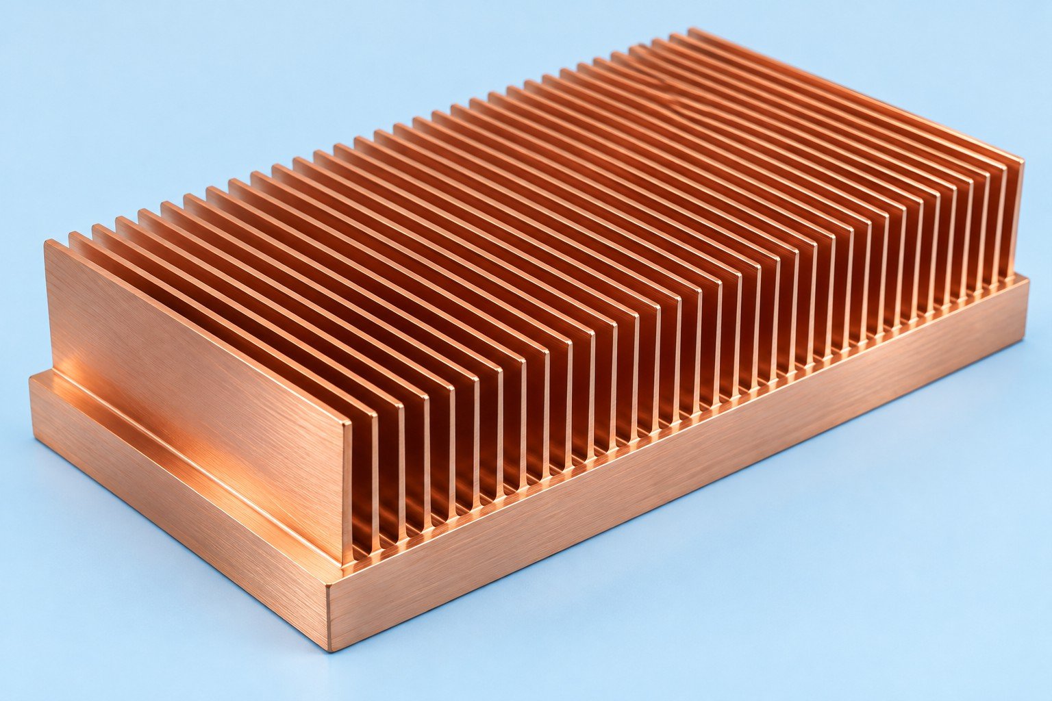
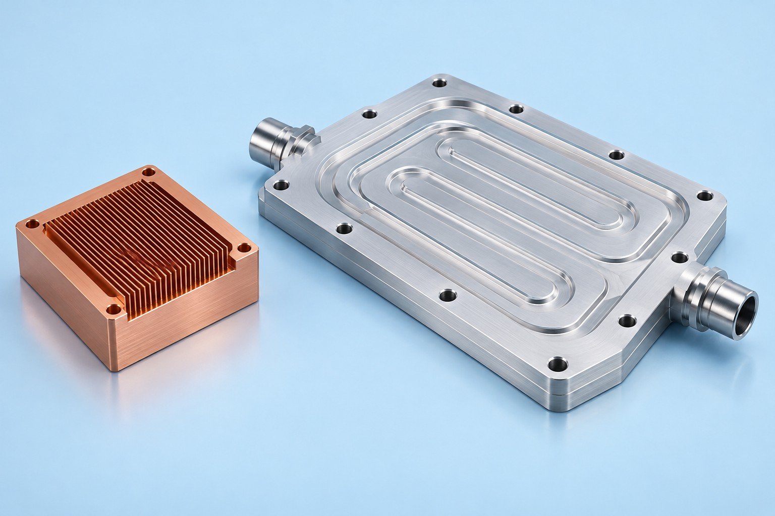
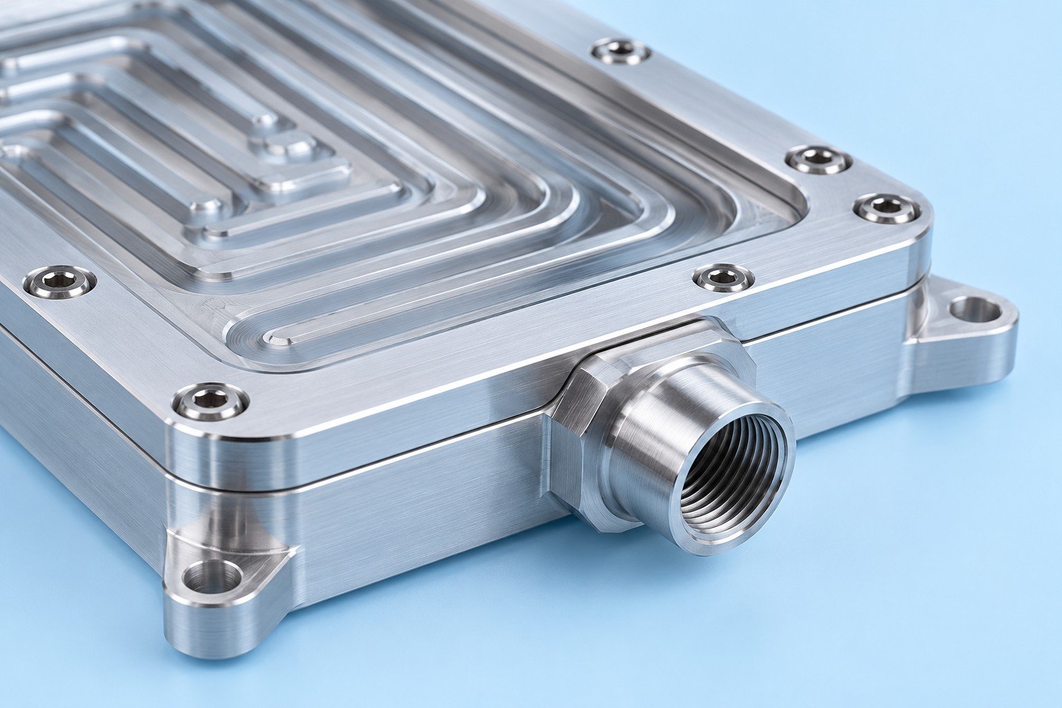
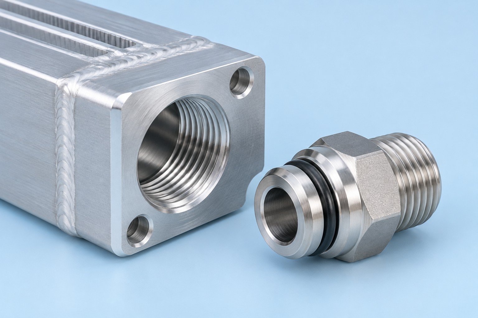
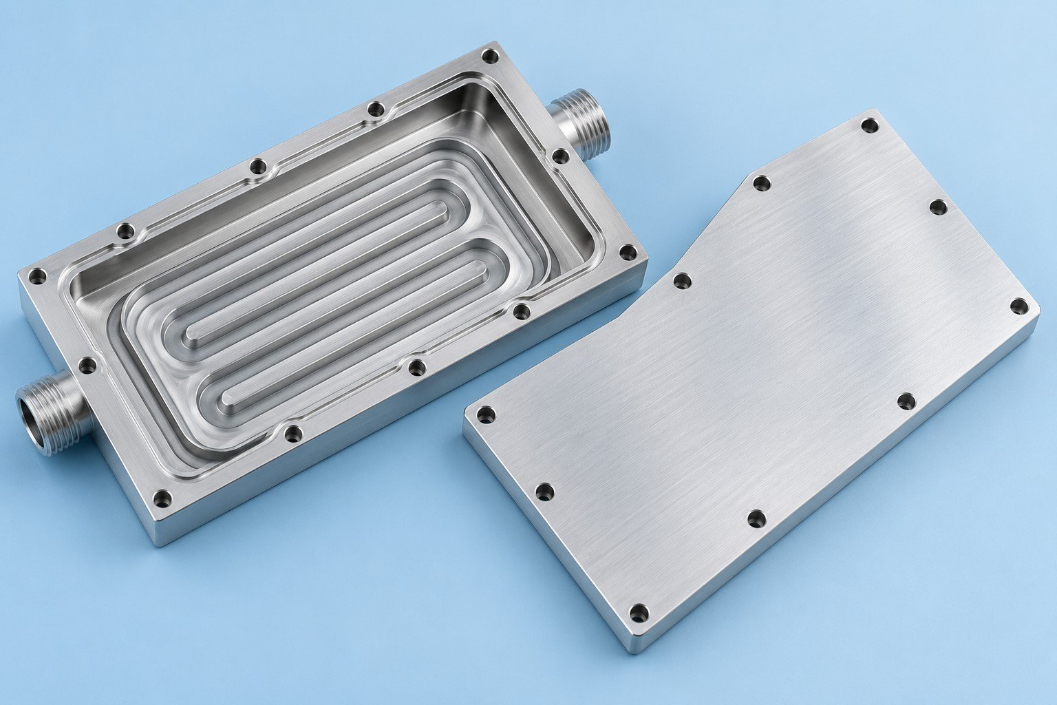
Make each approval specific enough to carry into the next build.
Share the heat map, drawing and operating conditions.
Review machining, joining and inspection scope.
Check the parts and interfaces on a sample.
Review dimensions and specified test records.
Confirm the accepted revision for repeat supply.
Define the records your team needs for acceptance; dimensional inspection alone does not verify thermal performance.
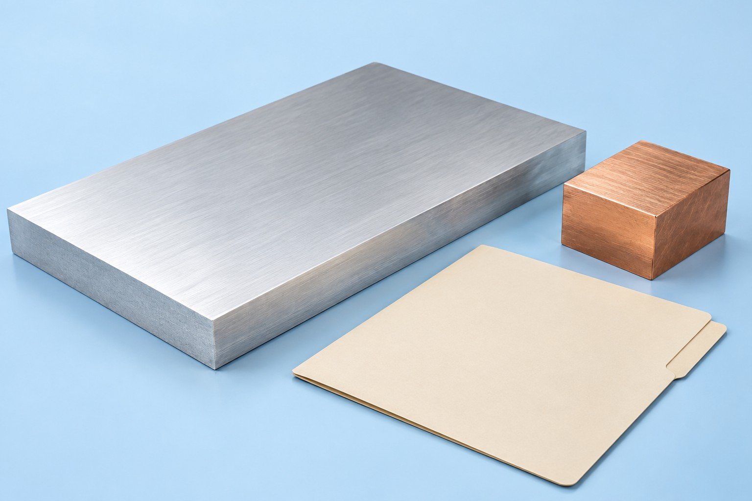
Material identity and the agreed supporting records
Drawing revision, stock condition and any specified temper
Your required traceability scope and retained evidence
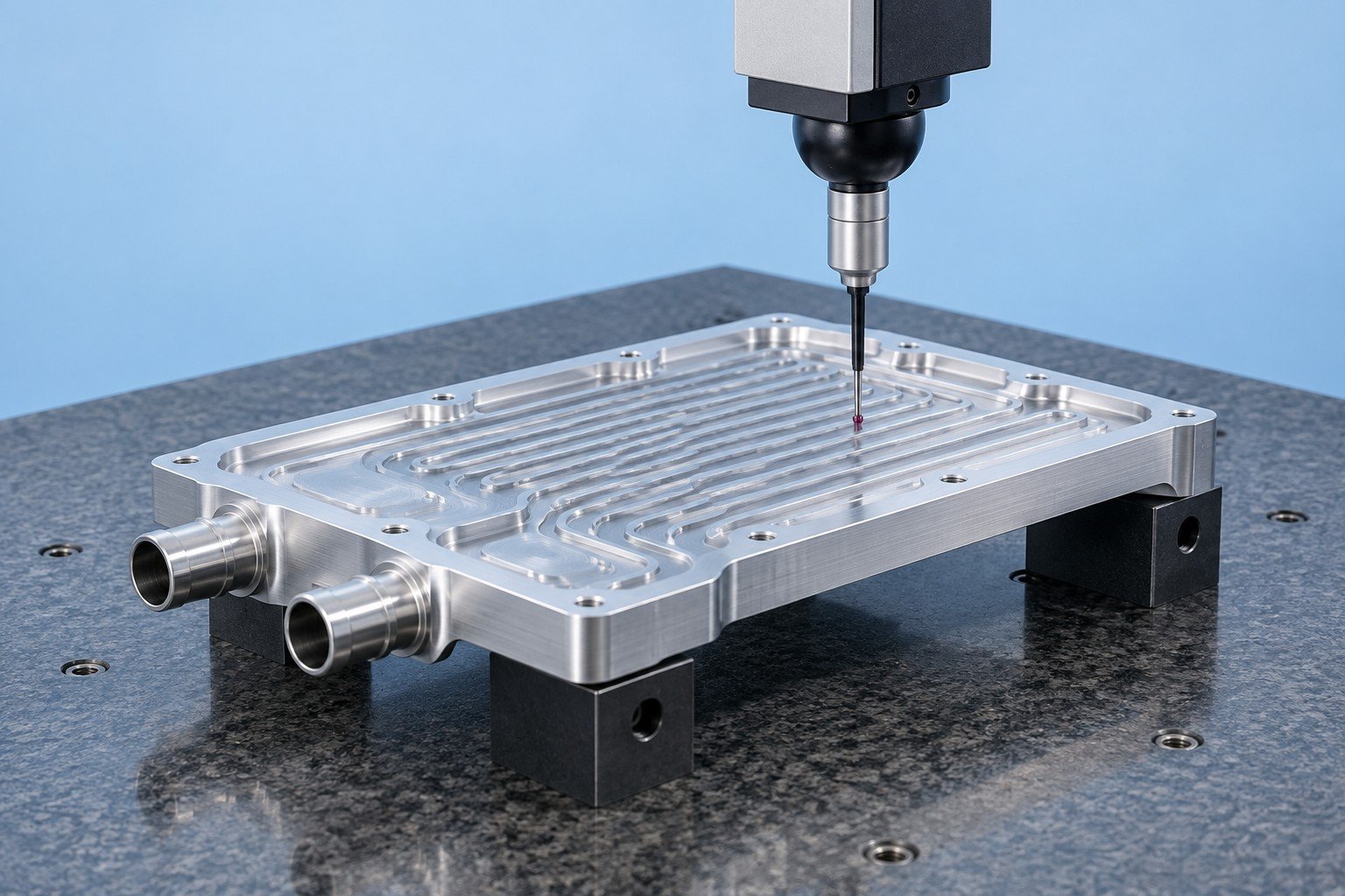
Contact faces, ports and mounting dimensions
Specified leak / pressure checks and acceptance records
Your assembly feedback before repeat production
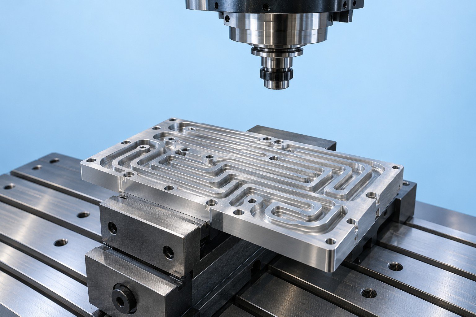
Critical dimensions after relevant machining or joining steps
Process checkpoints agreed for your part and order
Revision control when an approved feature changes
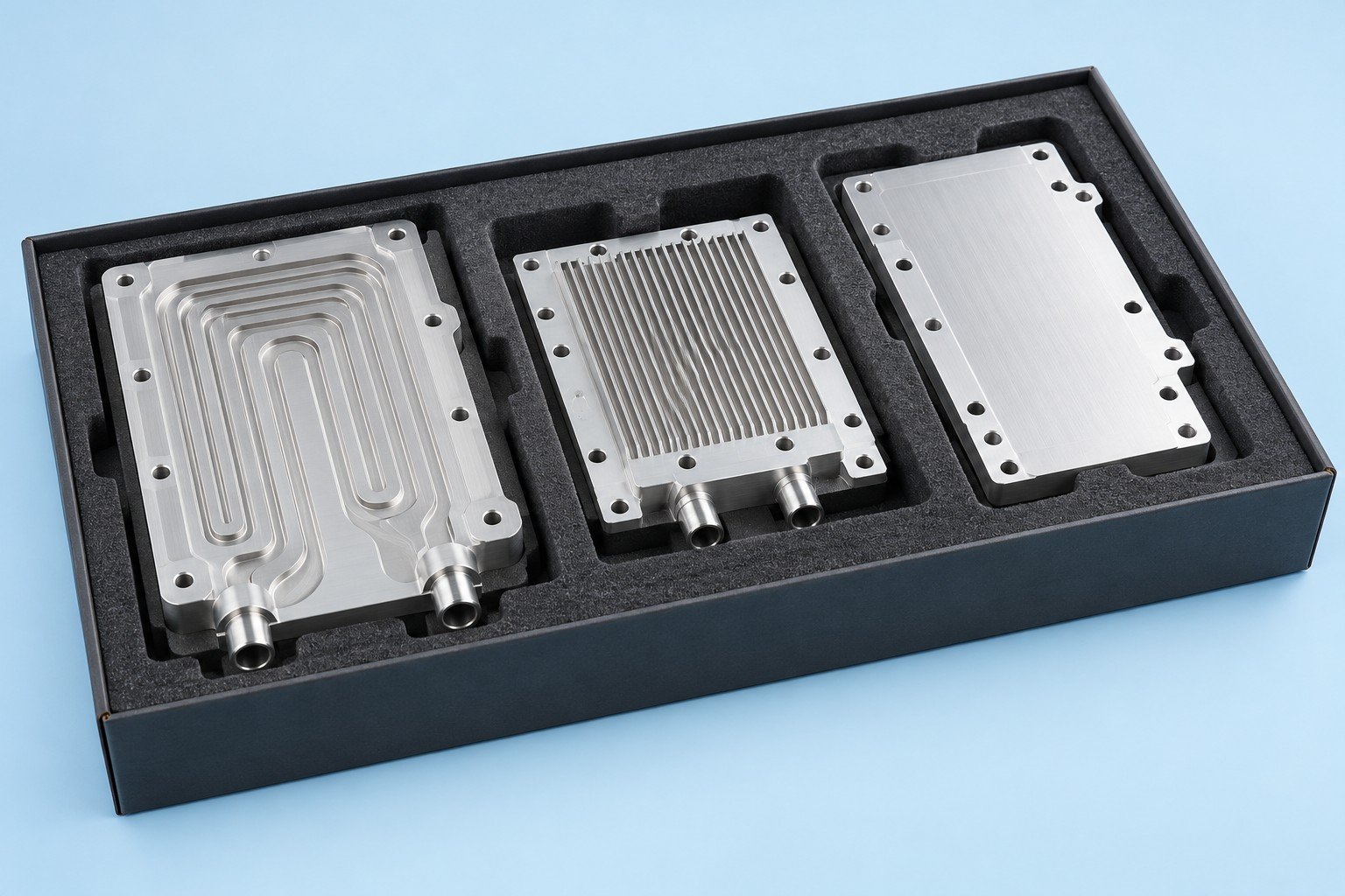
Final inspection and agreed test report scope
Quantity, part identification and protection of sealing faces
Documents and packaging required for your receiving team
Send the information that lets your reviewer resolve fit, flow and acceptance questions.
Compare the heat input, allowed component temperature, ambient conditions and installed airflow. Review liquid cooling when your air path or space cannot meet the application target. The decision needs your operating data; a component photograph cannot establish suitability.
Copper can offer higher bulk thermal conductivity, while aluminum can reduce component mass. Geometry, contact resistance, airflow or coolant conditions and your assembly all affect the result. Use the material chart as a property comparison, not a cooling-performance ranking.
Review the joint during drawing development. Alloy compatibility, cover thickness, tool access, internal geometry and the required seal determine which routes need further evaluation. Confirm the actual process and test scope before production.
Define the test medium, test pressure, hold time, leakage acceptance and sampling plan with your engineering team. Include the required record. A universal test pressure or a visual inspection is not a substitute for your application acceptance limits.
Review every wetted metal and the coolant supplier’s compatibility guidance. Dissimilar metals in a conductive coolant can create galvanic corrosion risk. Dry contact between aluminum and copper is a different interface from sharing a liquid circuit.
Confirm drawing revision, material, machining, joining, finishing, inspection and report scope, quantity, packaging and delivery terms. Thermal design, simulation or system validation is included only when expressly agreed for your project.