Injection Molding
Tooling and molding for your repeat plastic parts.
From prototype to production, coordinated manufacturing solutions for your custom parts.
View All Services →
Precision parts for your tight tolerances and complex geometry.
Tooling and molding for your repeat plastic parts.

Metal casting options for your part and production volume.

Cutting, forming and welding for your fabricated parts.

Custom profiles for your section, length and finish requirements.

Finishes for your appearance, corrosion and wear requirements.

Sub-assemblies and final builds for your production program.

Production tooling built around your process and volume.

Prototype parts to check fit, function and design.
DFM, process planning and production support for your project.
Inspection, documentation, inventory and delivery planning for your program.
Choose air- or liquid-cooling components around your thermal and mechanical requirements.

Manufacturing support for your cold plates, manifolds and cooling assemblies.

Find components for your power electronics, energy, laser and telecom application.

Components for your electronic systems.
Start with your functional and quality requirements.
Build around your operating environment.
From prototype to production, review material performance, manufacturability and cost for your part.
Review grade, temper and finish for your metal parts.
 AluminumStrength, weight and machining›
 Stainless SteelCorrosion and finish requirements›
 Carbon & Alloy SteelDiscuss grade and heat treatment›
 Tool SteelDiscuss tooling and wear needs›
 TitaniumReview grade and part geometry›
 Copper & Brass & BronzeDiscuss conductivity and machining›
Match your polymer to function, process and environment.
 ABSReview enclosure and molding needs›
 Polycarbonate (PC)Discuss clarity and impact needs›
 Nylon (PA)Review moisture and wear conditions›
 POM / AcetalReview fit and sliding features›
 PEEKDiscuss operating conditions›
 PTFEReview friction and chemical exposure›
 ULTEM / PEIDiscuss thermal and electrical needs›
Confirm grade availability and application requirements.
 Silicone / LSRDiscuss flexible component needs›
 TPU / TPEReview flexibility and processing›
 EPDMReview weathering and chemical exposure.›
 NBRReview oil and fuel exposure.›
 FKMReview temperature and chemical exposure.›
 G10 / FR4Review insulation and laminate needs›
 CompositesReview stiffness, weight and laminate.›Customer-Specified MaterialsConfirm your grade and requirements.›Other Specialty MaterialsDiscuss your application and grade.›
Practical guidance for your part geometry and material decisions.
Prepare your process, budget and sourcing questions.
Build your knowledge before production.
Learn who we are and how we operate.
Find our U.S. support team or start a conversation.
YOUR DRAWING · YOUR OPERATING CONDITIONS
Start with the cross-section your assembly needs. Compare an available profile with a new extrusion die, then define cut length, mounting machining, finish and the checks that protect your device interface.
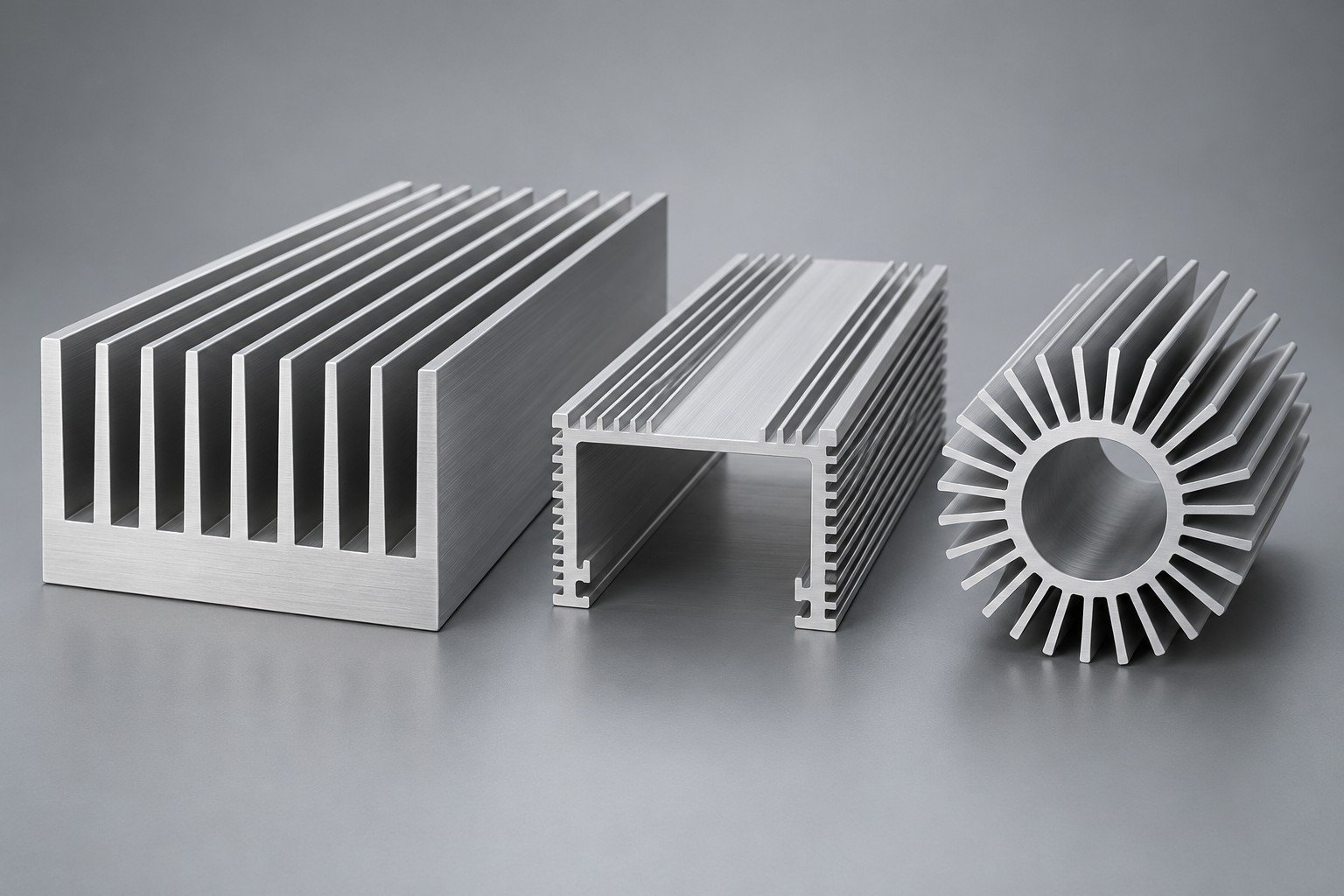
Illustrative component concept
Power, ambient & airflow
Contact face & mounting
Material, route & quantity
Sample, checks & records
Choose the route around your material, interfaces and order quantity. Drawing review confirms availability and manufacturing scope for your part.

Review interrupted geometry, tool access, fin rigidity and material removal.
Review this route →
Review integral thin fins, material condition and installed airflow.
Review this route →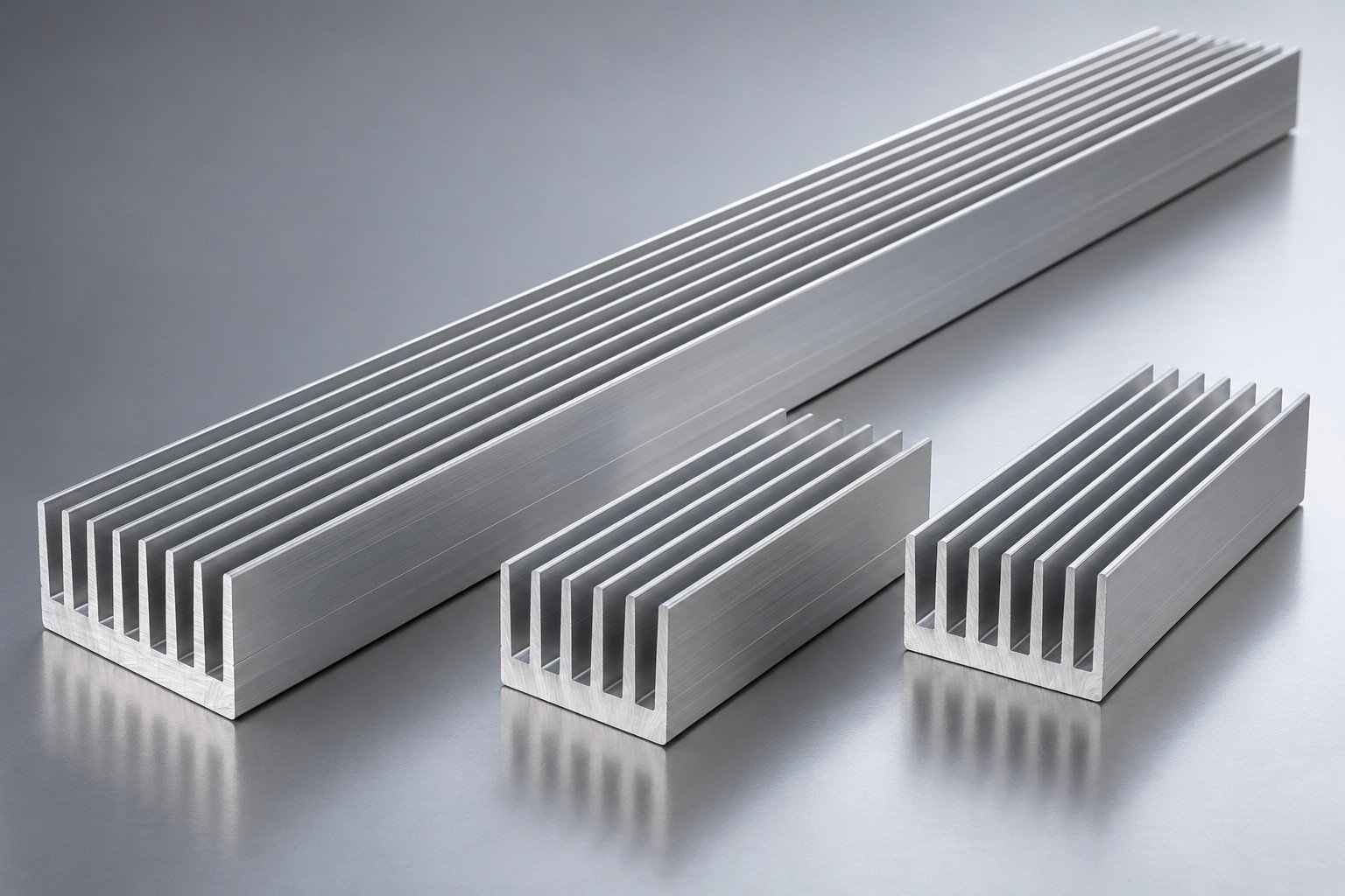
Compare an available section with a new die; specify cutting and machining.
Review this route →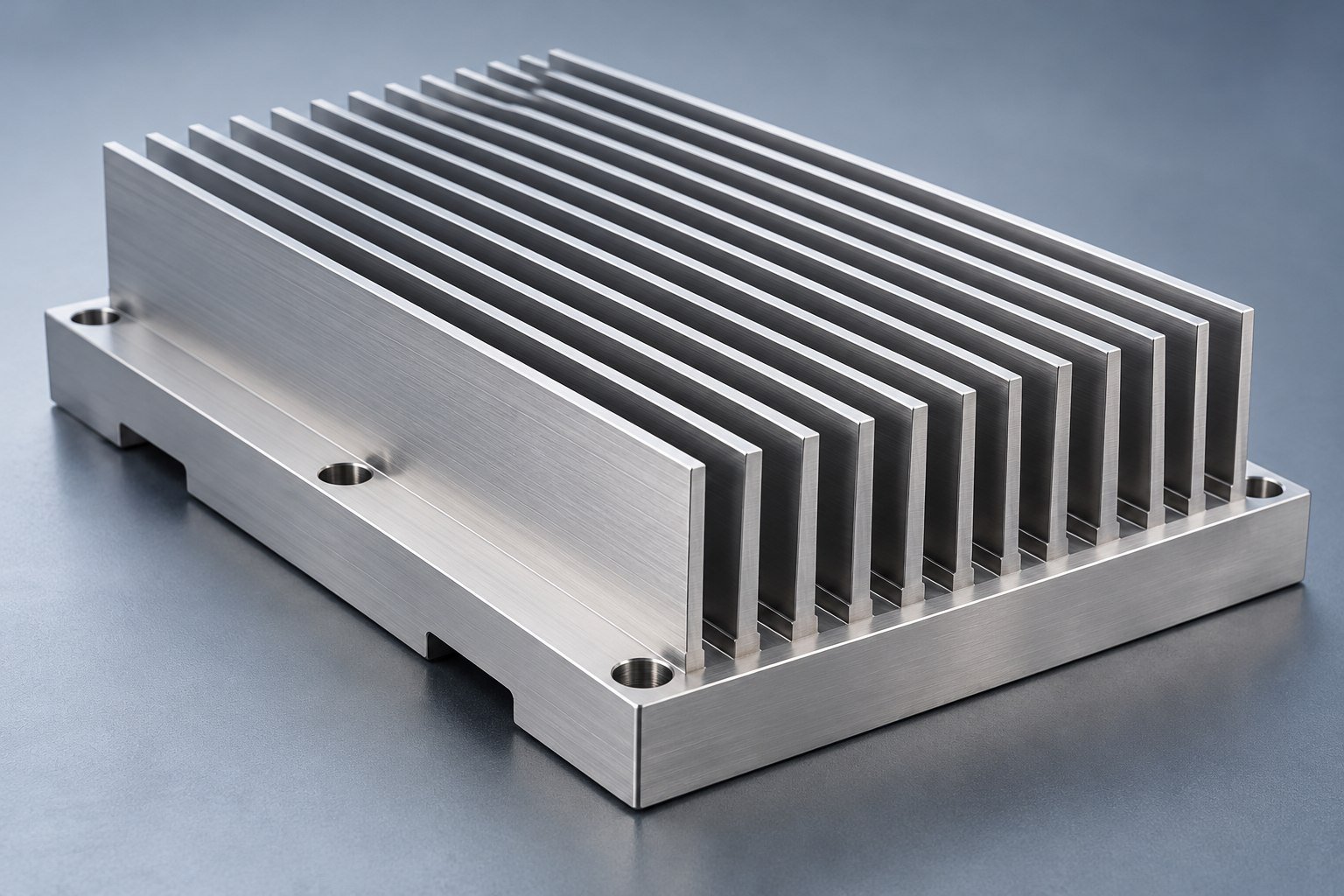
Review separate fins, base grooves, joint construction and agreed checks.
Review this route →Extruded heat sinks start with a constant cross-section. An existing profile may suit your envelope after cutting and secondary machining; a custom profile needs die feasibility, trial approval and quantity review before production.
Choose a section around your actual envelope. Review the profile, machining and die decision together before approving your extruded heat sink prototype.
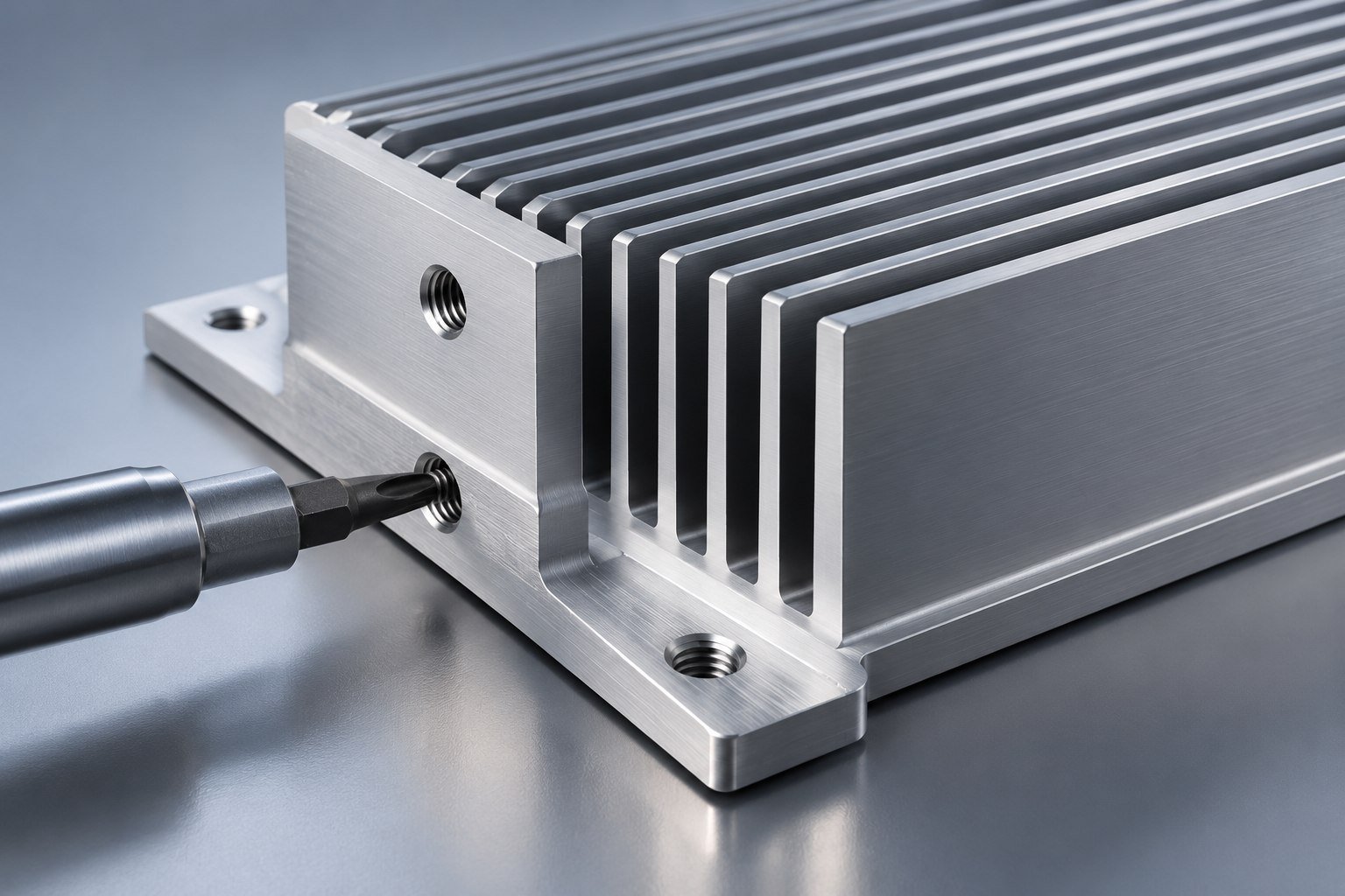
Allow tool and fastening access around your hole pattern.

Define the device footprint, TIM and clamping stack.
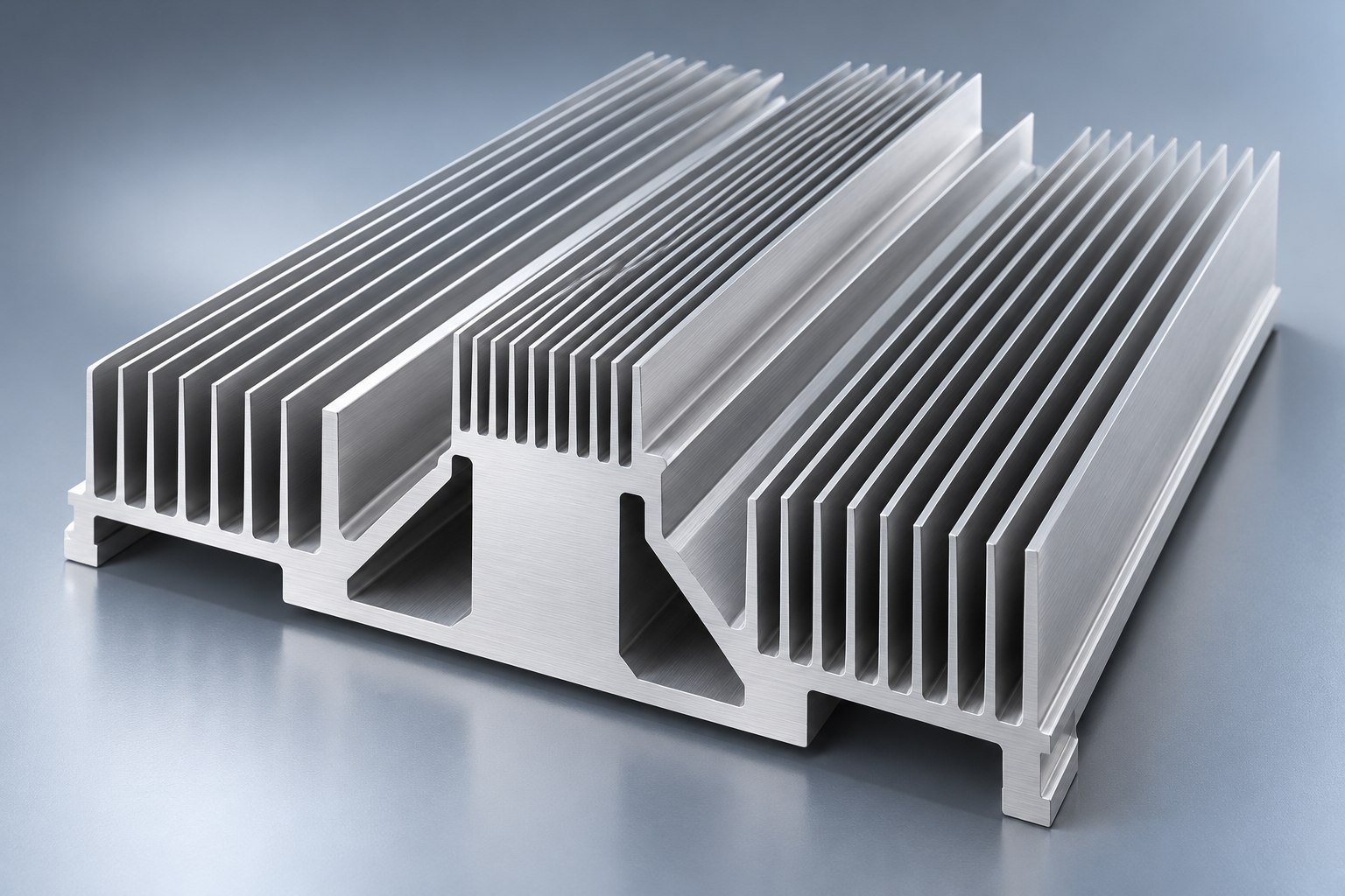
Review channel clearance in the installed assembly.
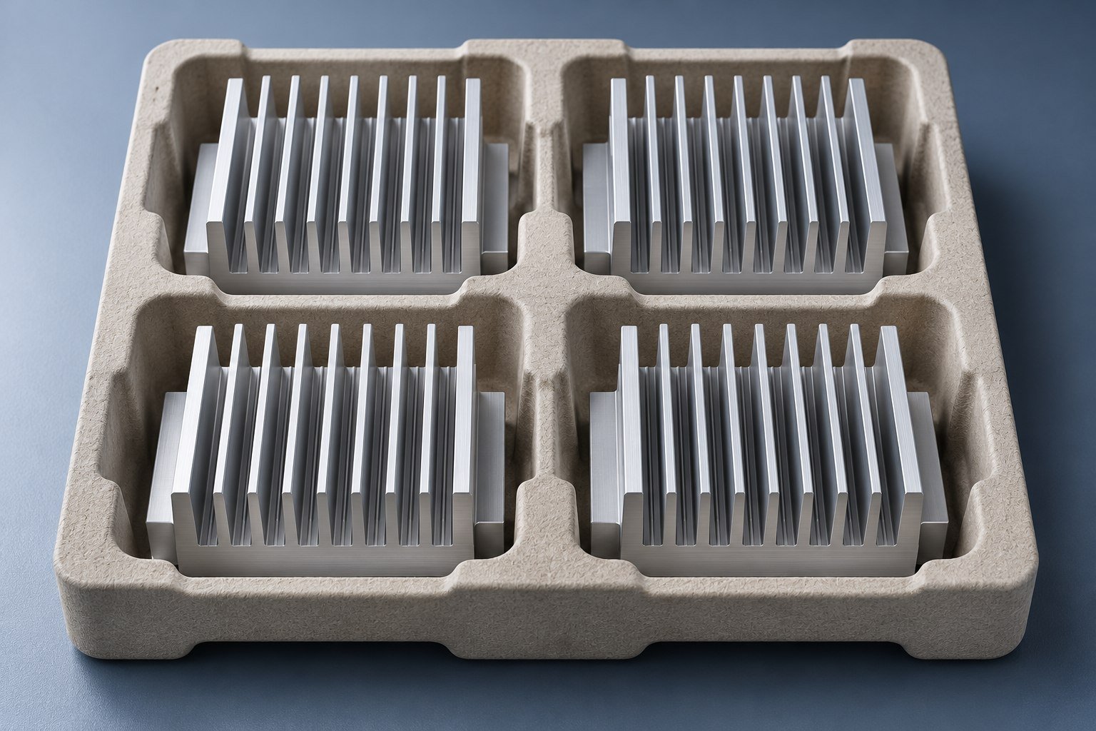
Agree handling, sample checks and the released revision.
Use bulk material properties to compare conduction and mass. Your finished part still needs geometry, mounting and airflow review; these figures are not LK MFG heat sink test results.
6061-T6: Hydro, 25°C. 6063-T5: Gabrian typical value. Confirm the specified temper.
Both aluminum grade families are about 2.70 g/cm³. Calculate finished mass from the approved section and length; a conductivity difference is not a weight difference.
| Grade | European designation | Si | Mg | Cu | Fe | Mn | Cr | Zn | Ti | Al |
|---|---|---|---|---|---|---|---|---|---|---|
| 6061 | EN AW-6061 · AlMg1SiCu | 0.40–0.80 | 0.80–1.20 | 0.15–0.40 | ≤0.70 | ≤0.15 | 0.04–0.35 | ≤0.25 | ≤0.15 | Balance |
| 6063 | EN AW-6063 · AlMg0.7Si | 0.20–0.60 | 0.45–0.90 | ≤0.10 | ≤0.35 | ≤0.10 | ≤0.10 | ≤0.10 | ≤0.10 | Balance |
For aluminum: other elements ≤0.05% each / ≤0.15% total. Values are reference limits; the ordered standard and material certificate govern. Confirm grade and temper feasibility for extruded heat sinks.
Material sources: Hydro 6061 · Gabrian 6063
Specify the visible surfaces and functional contacts separately. No coating gives a universal cooling improvement. Approve the finish on cut ends and machined faces as well as the profile surface.
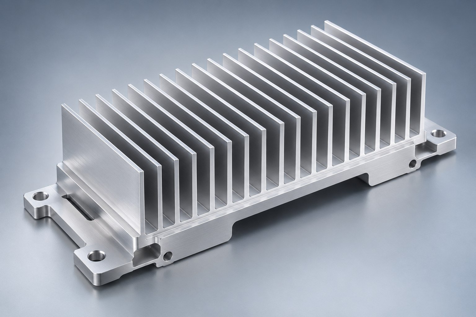
Confirm alloy, surface preparation, film and masking.
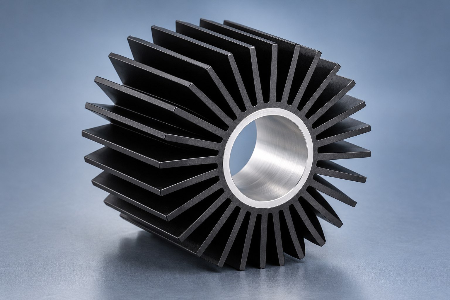
Specify appearance and keep thermal or electrical contacts controlled.
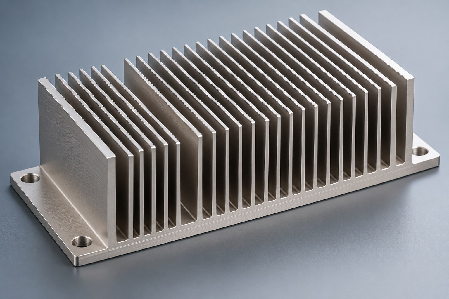
Review substrate preparation, coating thickness and required contact surfaces.
As-machined surfaces and selective coatings are reviewed against your drawing. Powder coating needs specific review of fin gaps, thickness and masked contact areas. Anodizing applies to aluminum, not copper.
Put the dimensions that control fit and heat transfer on your drawing.
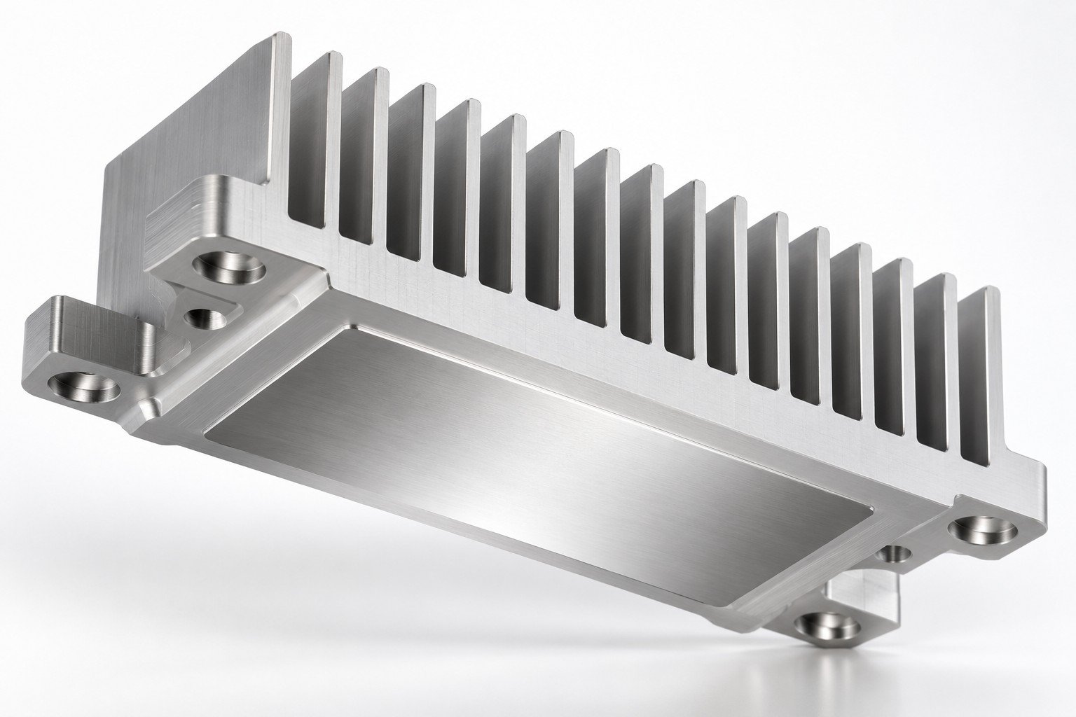
Hole pattern, datums and assembly loads
Thread standard, depth and tool access
Cable clearance, fixtures and interruptions
Footprint, flatness and surface condition
Base thickness, fin envelope and usable air path
Define your operating conditions and mating features before selecting a manufacturing route.
Your contact area, TIM and clamping condition determine which face needs a flatness requirement. Specify the datum and measurement state.
Device footprint and keep-outs
TIM and insulation stack
Datums and final inspection
Clamping and assembly condition
Do not select fin density from appearance alone. Review installed flow, fan pressure, bypass and orientation.
Fin thickness and clear spacing
Flow direction and fan curve
Duct and bypass clearance
Thermal test operating point
Call out the cut length, straightness, twist and fin envelope separately from machined contact faces, mounting holes and threads. Your aluminum extrusion heat sink needs clear datums and inspection states after cutting, machining and finishing.
Review mounting holes with fasteners, tools, cable routes and the contact plane. Include the mating specification.
Hole pattern and threads
Fastener and wrench access
Module and cable keep-outs
Assembly datum scheme
Compare conduction, mass and manufacturing feasibility. A material property does not alone establish device temperature.
Grade and product standard
Temper or copper condition
Mounting load and mass
Sample material evidence
Review finish and masking with your thermal, electrical and dimensional interfaces. Apply coating requirements only to suitable substrates.
Coating and thickness
Thermal and electrical pads
Threads and precision fits
Burrs and final cleanliness
Separate material identity, dimensional inspection and system thermal validation. State what your quotation and sample approval include.
Controlled drawing revision
Critical dimensions and fit
Defined thermal conditions
Sampling and required records
Confirm revision and critical interfaces.
Agree material, geometry and manufacturing scope.
Check your finished part and assembly fit.
Review agreed dimensions and separate thermal test scope.
Release the approved revision and packaging.
Three views for your review: a calculation, a resistance budget and a heat-path diagram. All examples below are illustrative—not measured part performance or a CFD result.
Example only: ΔT = Q × R. At a hypothetical R = 1 K/W, 50 W gives a 50 K rise. R must come from your defined path and actual operating conditions.
Illustrative allowable total R = (75°C − 25°C) / Q. This is a 50 K budget from the chosen reference point to ambient; include interfaces on that path.
Review contact, spreading and convection together. For a measured curve or CFD report, agree the geometry, heat source, airflow, orientation and validation scope first.
For your acceptance report: define power, heat-source area, TIM and mounting, sensor positions, ambient, installed airflow or velocity, orientation and stabilization. Do not compare CFM, LFM and fan free-air ratings as interchangeable conditions.
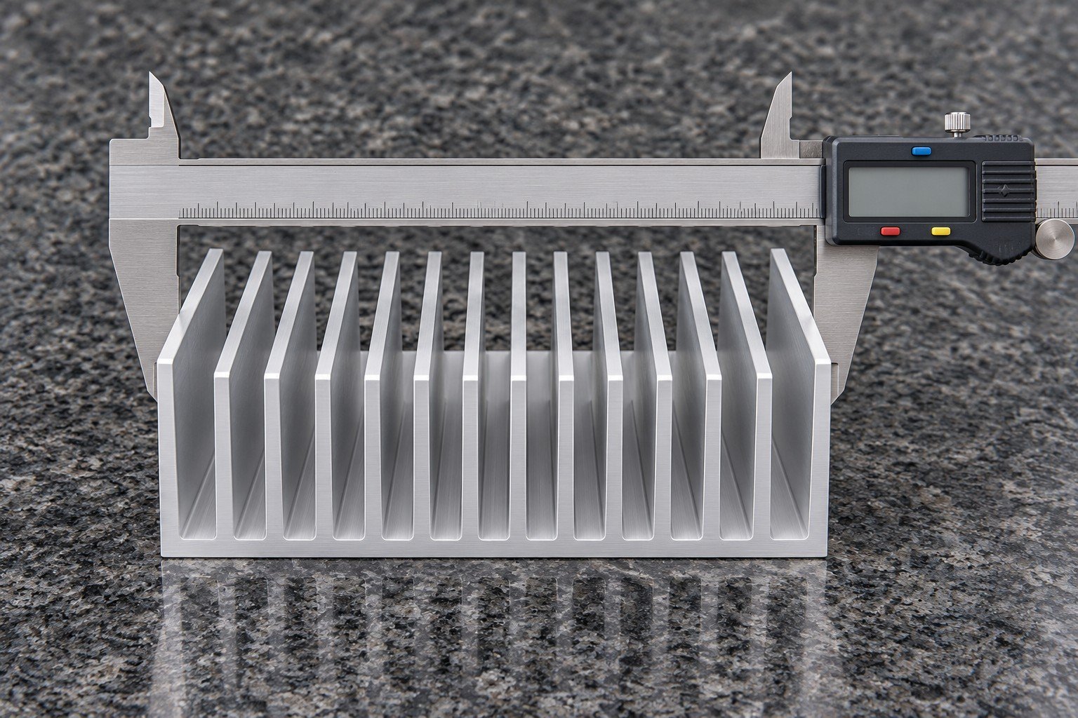
Illustrative component concept
An approved extrusion cross-section does not approve every finished cut length. Confirm heat sink secondary machining, burr removal, contact-face flatness, masking and packaging against the released drawing before repeat supply.
Project suitability, manufacturing scope and required records are confirmed from your drawing. These are application review topics, not customer case studies or system certifications.
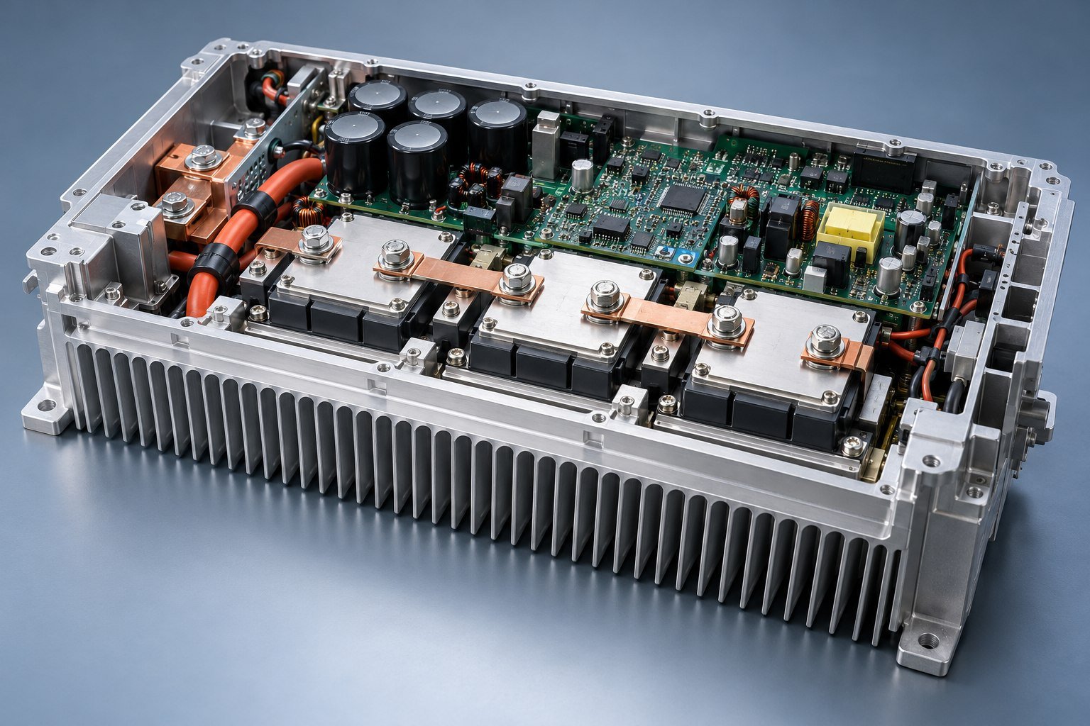
Review control cabinets, motor-drive enclosures and service access.
Match the module footprint, mounting load and insulation.
Review device heat load, mounting and environmental conditions.
Review airflow direction and the available enclosure volume.
Specify the board interface, orientation and ambient conditions.
Review the exact device and installed airflow; no generic fit assumption.
Plan instrument clearances, fixture mounting and service access.
Review power modules, ambient range and the assembly envelope.
Your quote should identify tooling, component manufacture, finishing, inspection and any separately agreed thermal validation. Manufacturing in China with Dallas-area coordination.
Compare available profiles with the required cross-section, fin envelope and mounting features. A new die is reviewed when existing geometry cannot meet the assembly; tooling cost and trial scope belong in the quote.
Provide the profile or section drawing, finished length, hole pattern, threads, datum surfaces and quantity. Review cutting and secondary machining as part of the finished component scope.
6063 is commonly considered for extrusion geometry and finish; 6061 can suit structural and machined features. Select the complete alloy and temper with extrusion feasibility, contact requirements and the thermal design.
Yes. Identify natural or forced convection, orientation, inlet conditions, installed airflow and bypass clearances. A profile curve from a different test setup may not represent your assembly.
No universal gain can be promised. Review coating thickness, contact masking, electrical isolation and the balance of radiation and convection in your application.
Profile availability, die and trial work, cut length, material and temper, order quantity, machining, finish, inspection, packaging and the agreed delivery schedule.