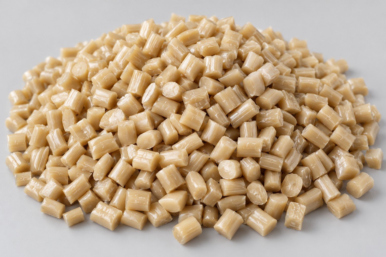
Injection Molding
Tooling and molding for your repeat plastic parts.
From prototype to production, coordinated manufacturing solutions for your custom parts.
View All Services →
Precision parts for your tight tolerances and complex geometry.
Tooling and molding for your repeat plastic parts.

Metal casting options for your part and production volume.

Cutting, forming and welding for your fabricated parts.

Custom profiles for your section, length and finish requirements.

Finishes for your appearance, corrosion and wear requirements.

Sub-assemblies and final builds for your production program.

Production tooling built around your process and volume.

Prototype parts to check fit, function and design.
DFM, process planning and production support for your project.
Inspection, documentation, inventory and delivery planning for your program.
Choose air- or liquid-cooling components around your thermal and mechanical requirements.

Manufacturing support for your cold plates, manifolds and cooling assemblies.

Find components for your power electronics, energy, laser and telecom application.

Components for your electronic systems.
Start with your functional and quality requirements.
Build around your operating environment.
From prototype to production, review material performance, manufacturability and cost for your part.
Review grade, temper and finish for your metal parts.
 AluminumStrength, weight and machining›
 Stainless SteelCorrosion and finish requirements›
 Carbon & Alloy SteelDiscuss grade and heat treatment›
 Tool SteelDiscuss tooling and wear needs›
 TitaniumReview grade and part geometry›
 Copper & Brass & BronzeDiscuss conductivity and machining›
Match your polymer to function, process and environment.
 ABSReview enclosure and molding needs›
 Polycarbonate (PC)Discuss clarity and impact needs›
 Nylon (PA)Review moisture and wear conditions›
 POM / AcetalReview fit and sliding features›
 PEEKDiscuss operating conditions›
 PTFEReview friction and chemical exposure›
 ULTEM / PEIDiscuss thermal and electrical needs›
Confirm grade availability and application requirements.
 Silicone / LSRDiscuss flexible component needs›
 TPU / TPEReview flexibility and processing›
 EPDMReview weathering and chemical exposure.›
 NBRReview oil and fuel exposure.›
 FKMReview temperature and chemical exposure.›
 G10 / FR4Review insulation and laminate needs›
 CompositesReview stiffness, weight and laminate.›Customer-Specified MaterialsConfirm your grade and requirements.›Other Specialty MaterialsDiscuss your application and grade.›
Practical guidance for your part geometry and material decisions.
Prepare your process, budget and sourcing questions.
Build your knowledge before production.
Learn who we are and how we operate.
Find our U.S. support team or start a conversation.
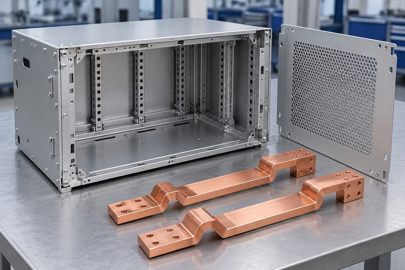
YOUR ENCLOSURE. YOUR CONNECTIONS. YOUR INSTALLED ASSEMBLY.
For your energy storage enclosure manufacturer review, connect mounting, access, coating and electrical interfaces to the released assembly drawing. Define the component scope before approving production.
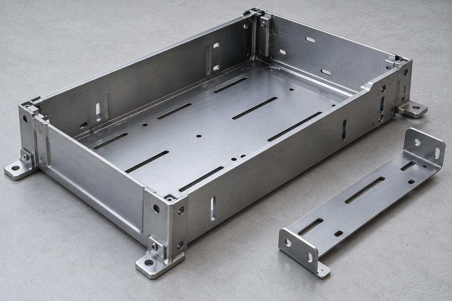
Share the equipment envelope, attachment points and service clearances.
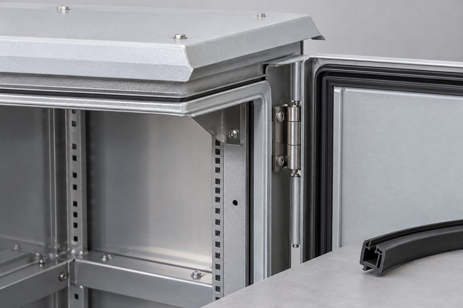
Identify indoor/outdoor exposure, condensation and cleaning conditions.
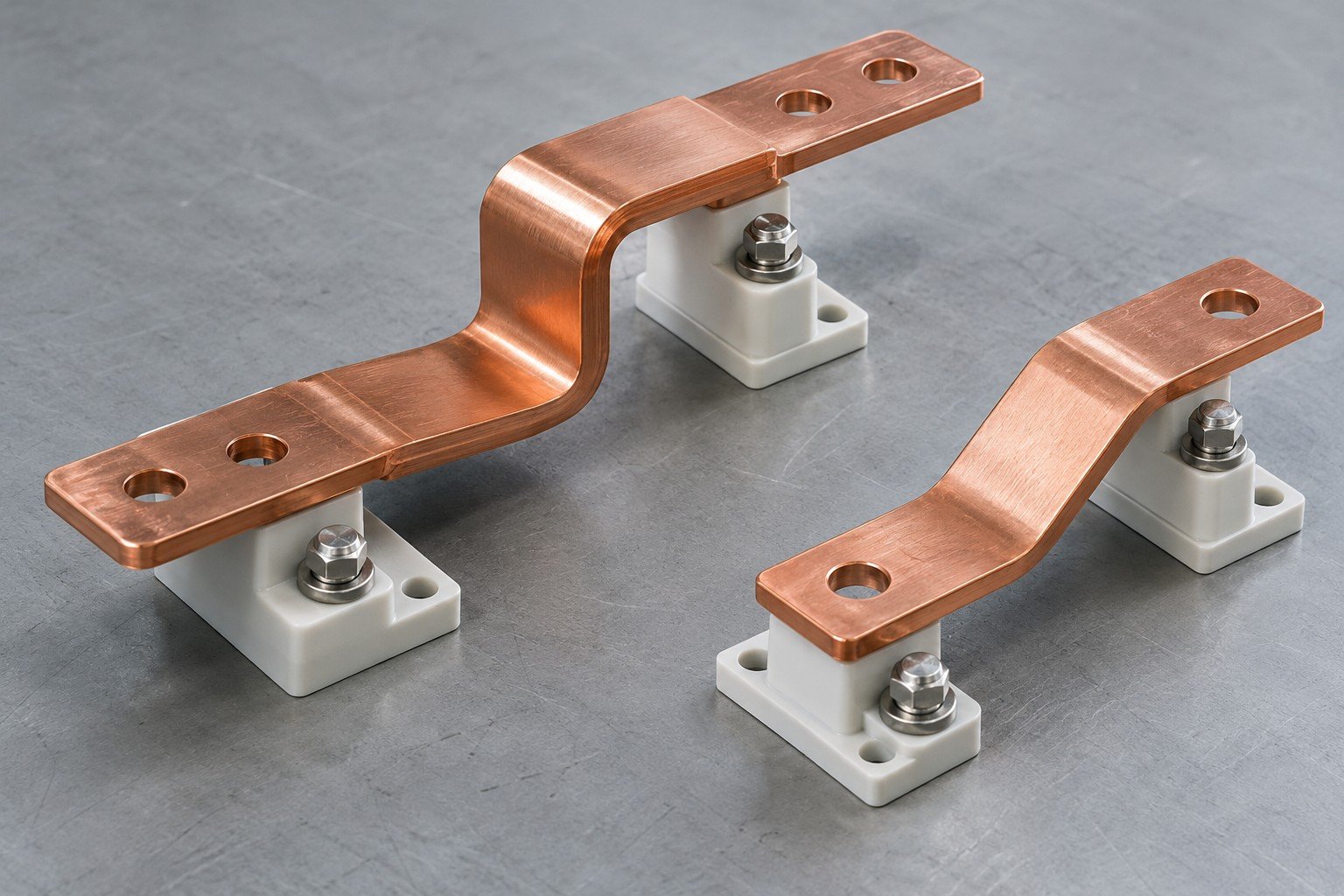
Define busbar contacts, insulation interfaces and cable openings.
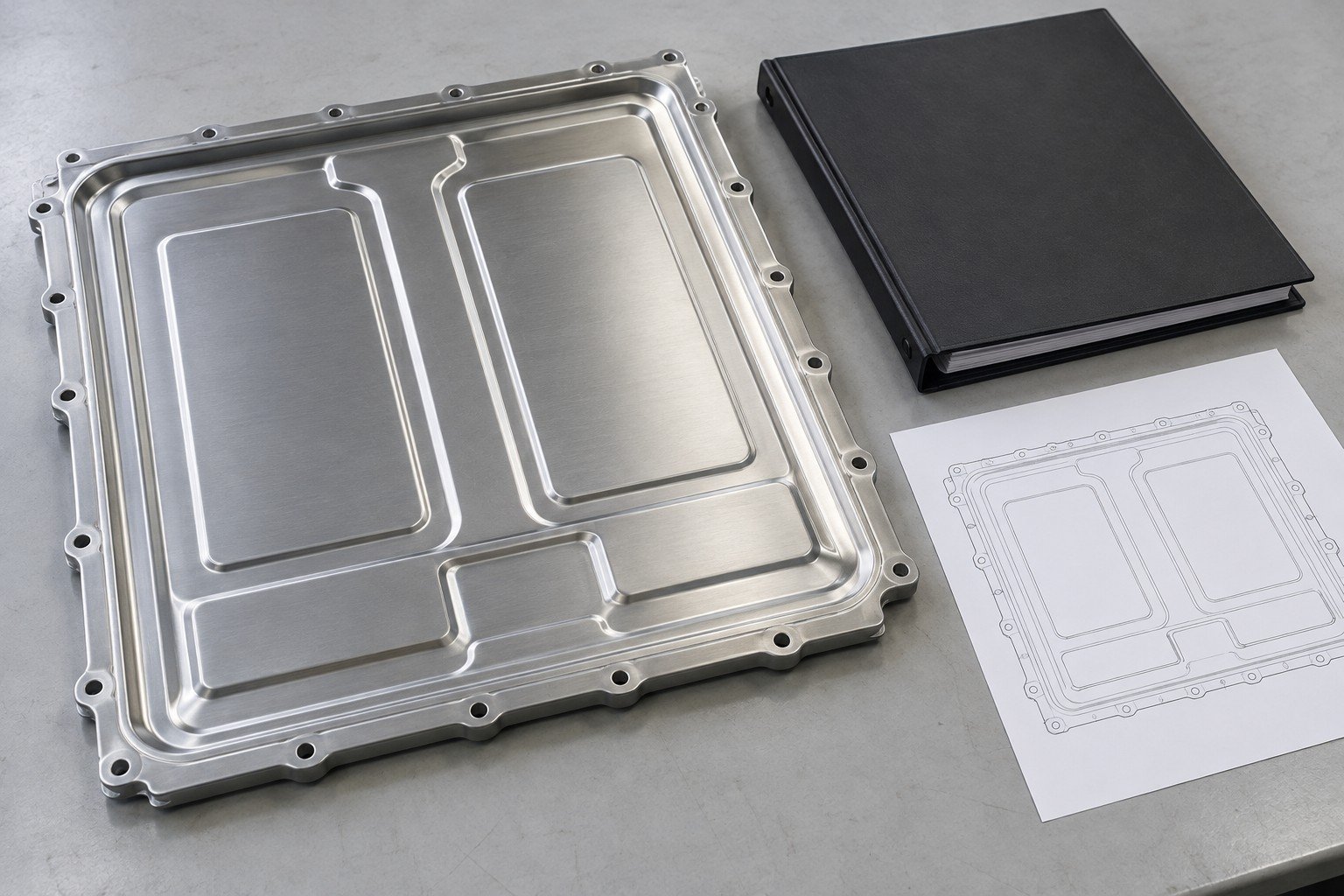
Agree part inspection and separate system-level validation.
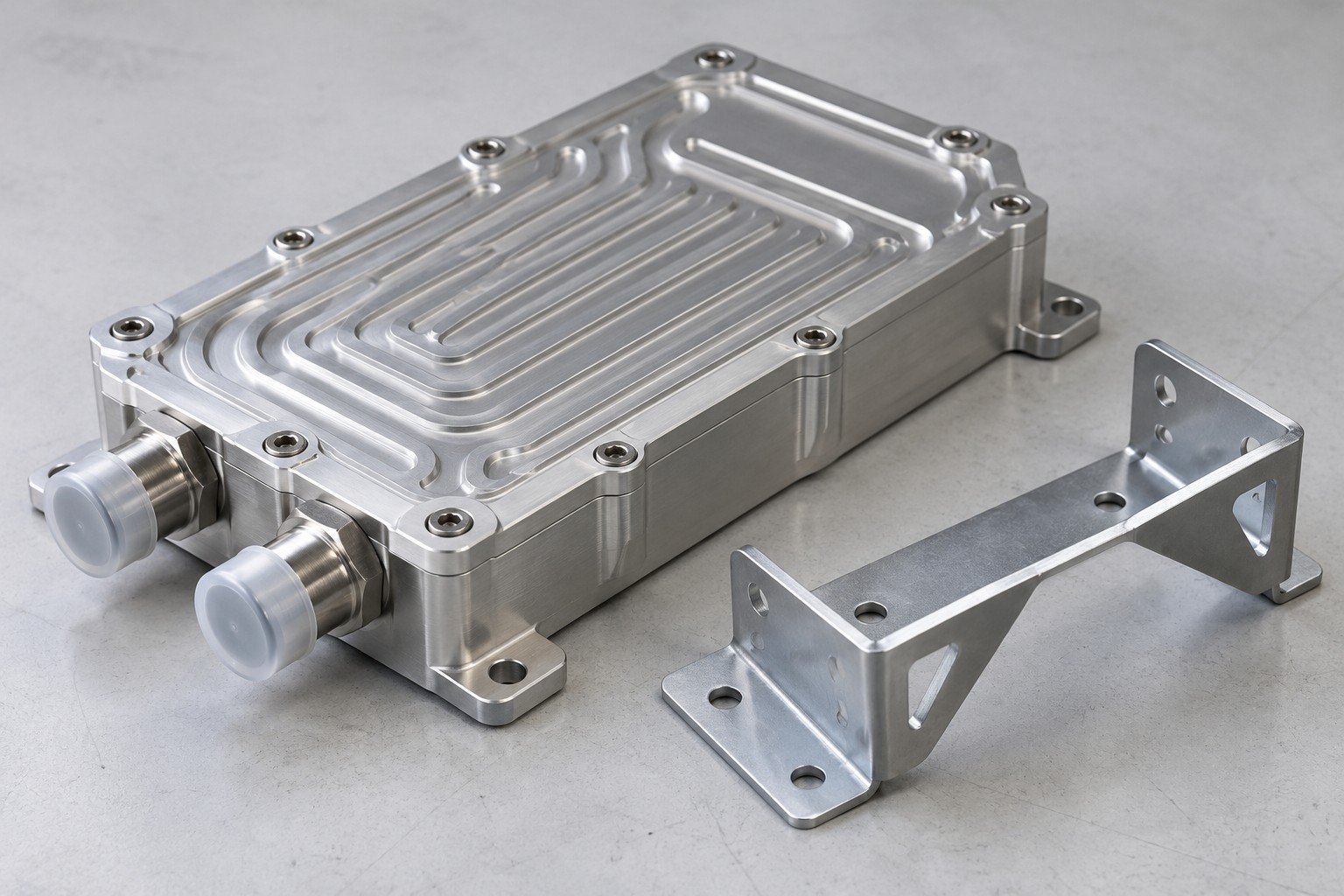
Illustrative component concepts · confirm your drawing and approval scope.
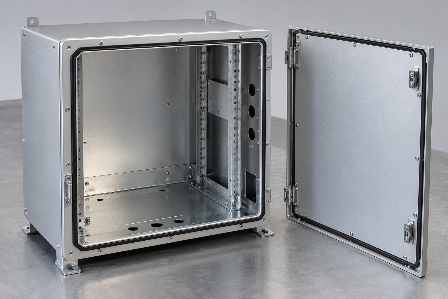
Review formed panels, door/cover access, fastening, seals and protected contact areas.
Review formed enclosures →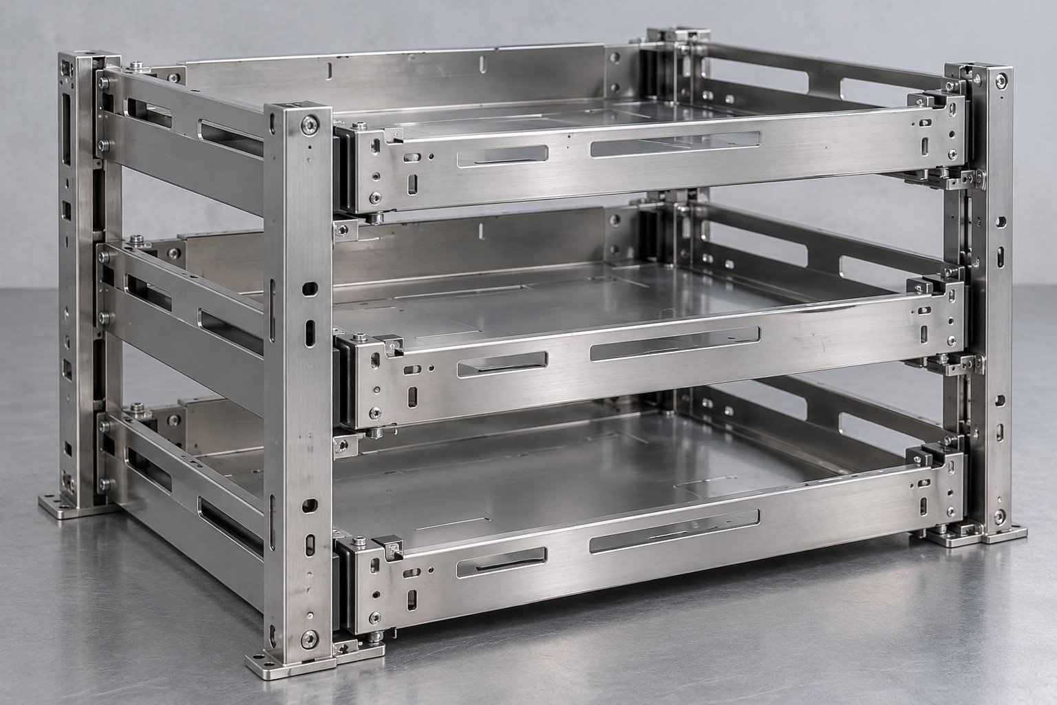
For custom battery rack fabrication, provide module dimensions, mounting details and the load/approval requirements from the system owner.
Review assembly scope →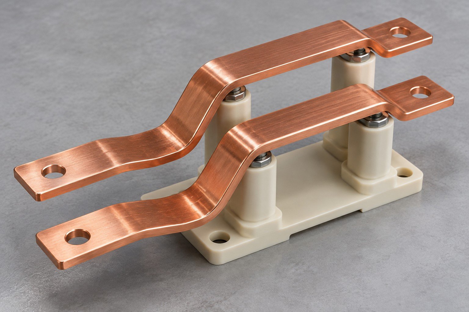
For your energy storage busbar manufacturer review, define conductor material, bends, hole patterns, surface condition and the electrical approval scope.
Review specified material →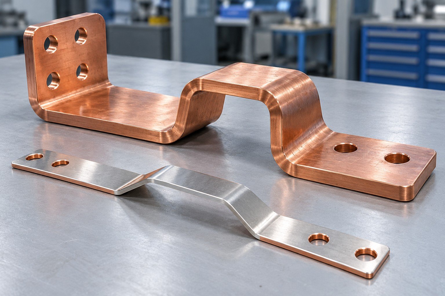
Keep the electrical interface drawing connected to the mechanical part drawing. Identify contact faces, bend transitions, hole locations and surfaces that need masking or treatment.
This isolated calculation compares electrical loss at one constant, assumed resistance. It does not predict busbar temperature or establish an allowable current.
R = 0.00010 Ω; P = I²R. Vertical baseline 0–10 W; current shown from 100–300 A.
100² × 0.00010 = 1 W; 200² × 0.00010 = 4 W; 300² × 0.00010 = 9 W. Constant resistance is an assumption, not measured product data.
Contact geometry, surface condition, joint design, temperature-dependent resistance, cooling, insulation and protective devices require the system designer’s review. A material certificate or conductor appearance cannot establish ampacity or system safety.
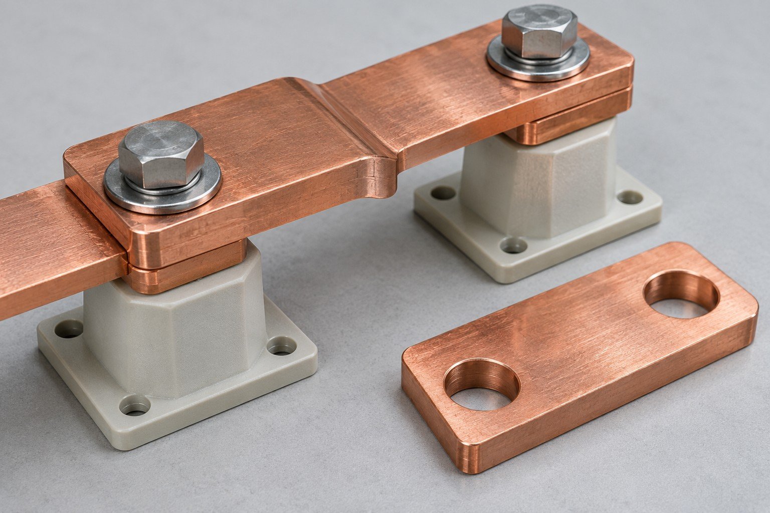
Contact geometry and insulation concept · not a tested current rating.
This is not a busbar sizing method or a complete thermal model. Actual connection resistance and operating conditions need their own evidence.
For energy storage enclosure sheet metal fabrication, review bend access, hardware, seams and the final assembled condition before choosing the route.
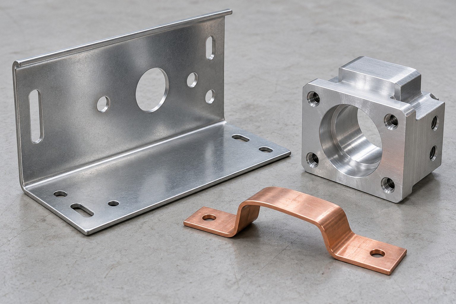
| Your component | Route to review | Input your drawing needs |
|---|---|---|
| Panels, trays and covers | Cutting and forming | Thickness, bends, cutouts, edges and hardware |
| Mounting blocks or locating faces | CNC machining | Datums, mating features and accessible tooling |
| Busbar blanks and shaped links | Agreed cutting, forming and finishing route | Material, bends, contact geometry and protected surfaces |
| Multi-part rack or bracket groups | Joining and mechanical assembly | Component revisions, fastening and agreed sample checks |
ENVIRONMENT · FINISH · ASSEMBLY · APPROVAL
For corrosion resistant energy storage enclosures, specify the environment and coating requirements rather than relying on a generic finish name.
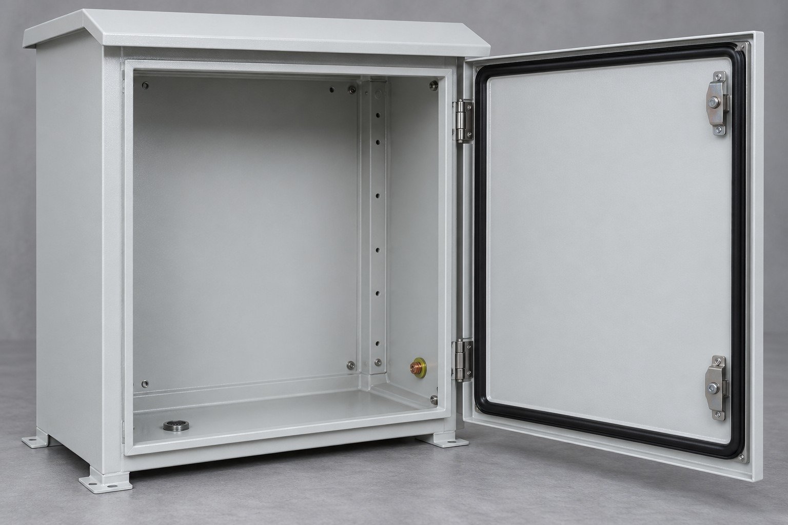
State rain, salt exposure, temperature, condensation and cleaning conditions.
Mark appearance zones, masked contacts and treatment requirements.
Review seals, fasteners, drainage and service access.
Define which organization approves environmental and electrical performance.
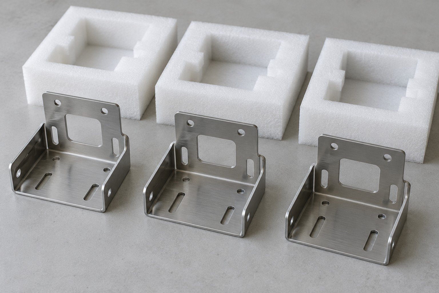
Share the revision, interfaces and actual application.
Review geometry, material and manufacturing sequence.
Check the agreed features and mating condition.
Review specified records and approval responsibility.
Confirm repeat scope, packaging and delivery plan.
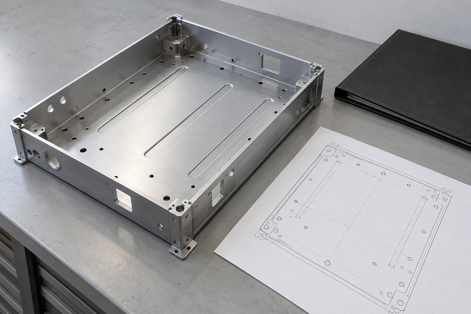
Share the actual exposure, operating temperature, condensation, cleaning and coating requirements. Define interfaces and environmental validation with the system owner; a material or finish name alone does not establish an enclosure rating.
No. It uses an assumed constant resistance to illustrate P = I²R. Temperature, cooling, connection details, insulation and protection are outside that simple calculation.
This page concerns drawing-based enclosures, racks, busbars and mechanical components. Battery cells, controls, installed electrical design and system certification need an explicitly agreed separate scope.
Share CAD, controlled drawings, mating interfaces, material and finish, environment, trial/repeat quantities and the required inspection and validation records.