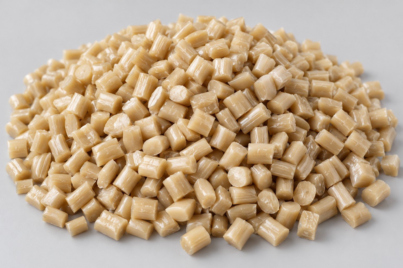
Injection Molding
Tooling and molding for your repeat plastic parts.
From prototype to production, coordinated manufacturing solutions for your custom parts.
View All Services →
Precision parts for your tight tolerances and complex geometry.
Tooling and molding for your repeat plastic parts.

Metal casting options for your part and production volume.

Cutting, forming and welding for your fabricated parts.

Custom profiles for your section, length and finish requirements.

Finishes for your appearance, corrosion and wear requirements.

Sub-assemblies and final builds for your production program.

Production tooling built around your process and volume.

Prototype parts to check fit, function and design.
DFM, process planning and production support for your project.
Inspection, documentation, inventory and delivery planning for your program.
Choose air- or liquid-cooling components around your thermal and mechanical requirements.

Manufacturing support for your cold plates, manifolds and cooling assemblies.

Find components for your power electronics, energy, laser and telecom application.

Components for your electronic systems.
Start with your functional and quality requirements.
Build around your operating environment.
From prototype to production, review material performance, manufacturability and cost for your part.
Review grade, temper and finish for your metal parts.
 AluminumStrength, weight and machining›
 Stainless SteelCorrosion and finish requirements›
 Carbon & Alloy SteelDiscuss grade and heat treatment›
 Tool SteelDiscuss tooling and wear needs›
 TitaniumReview grade and part geometry›
 Copper & Brass & BronzeDiscuss conductivity and machining›
Match your polymer to function, process and environment.
 ABSReview enclosure and molding needs›
 Polycarbonate (PC)Discuss clarity and impact needs›
 Nylon (PA)Review moisture and wear conditions›
 POM / AcetalReview fit and sliding features›
 PEEKDiscuss operating conditions›
 PTFEReview friction and chemical exposure›
 ULTEM / PEIDiscuss thermal and electrical needs›
Confirm grade availability and application requirements.
 Silicone / LSRDiscuss flexible component needs›
 TPU / TPEReview flexibility and processing›
 EPDMReview weathering and chemical exposure.›
 NBRReview oil and fuel exposure.›
 FKMReview temperature and chemical exposure.›
 G10 / FR4Review insulation and laminate needs›
 CompositesReview stiffness, weight and laminate.›Customer-Specified MaterialsConfirm your grade and requirements.›Other Specialty MaterialsDiscuss your application and grade.›
Practical guidance for your part geometry and material decisions.
Prepare your process, budget and sourcing questions.
Build your knowledge before production.
Learn who we are and how we operate.
Find our U.S. support team or start a conversation.
YOUR VISIBLE SURFACES. YOUR CONNECTORS. YOUR FINAL FIT.
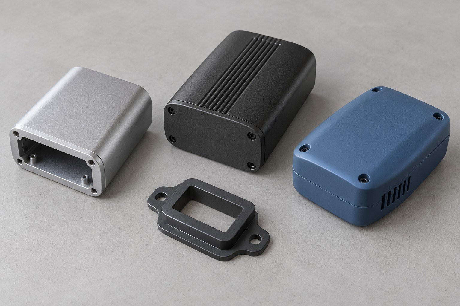
Define your custom aluminum electronics housing around visible surfaces, mounting features and the assembled fit. Review your material, manufacturing route and finished condition before approving a sample.
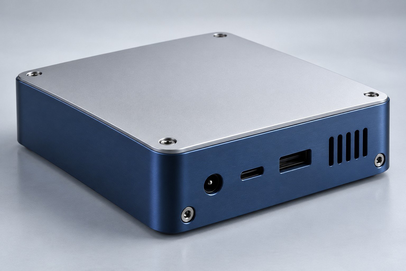
Mark cosmetic faces and agree the reference sample.
Identify the lid, locating lip, screws and connectors.
State masking and whether dimensions apply after finish.
Separate prototype review from repeat-production approval.
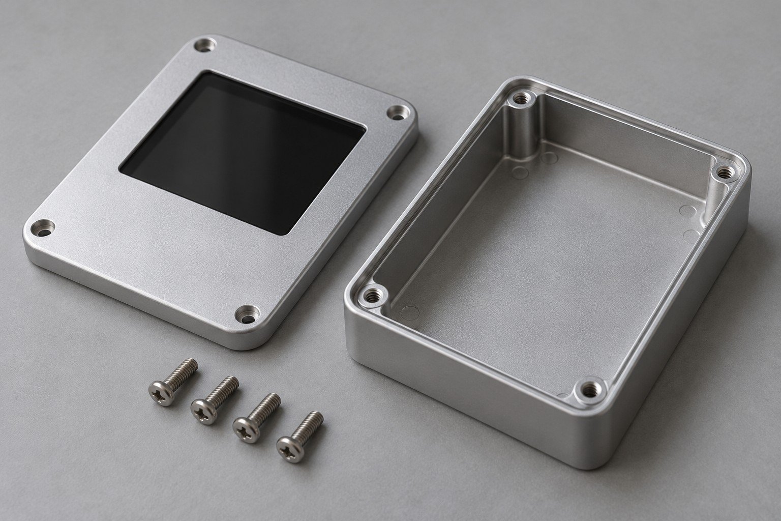
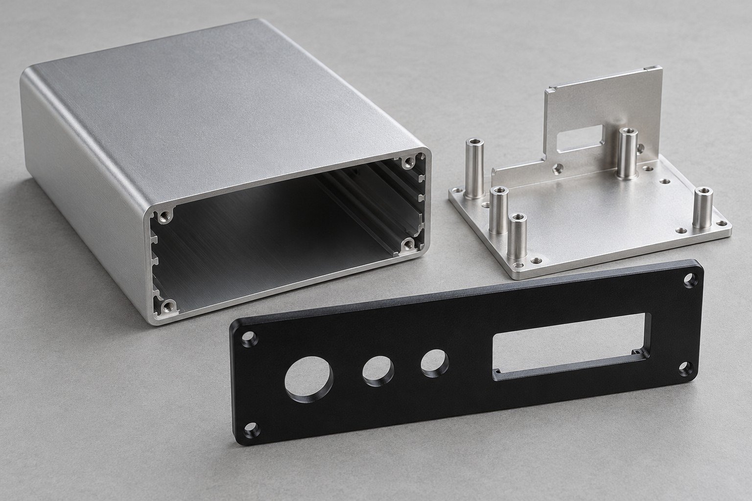
Review wall geometry, edge details, mounting bosses and accessible assembly features.
Define button bores, connector cutouts, display openings and controlled visible edges.
Connect brackets and locating features to the actual circuit-board or subassembly drawing.
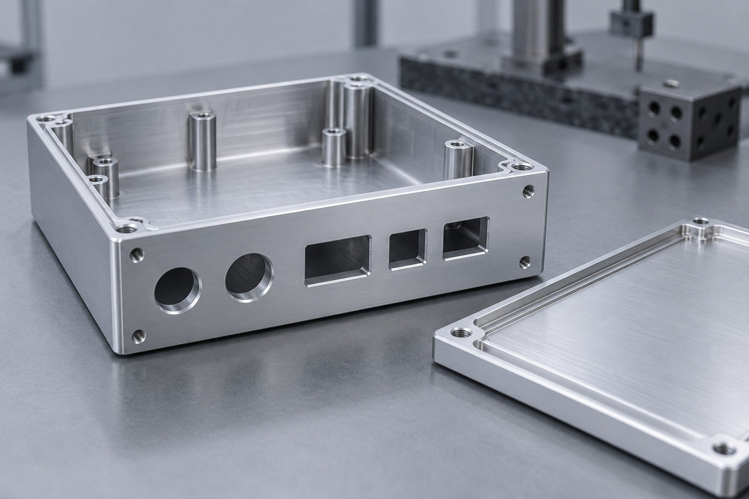
A cover that fits before coating may need a different acceptance plan after finishing. Identify each contact face, thread, recess and locating feature.
This geometric example isolates one question: how much clearance remains when two opposing faces each build outward? It is not an anodizing-growth model or a measured product result.
Assumed initial gap 100 µm; outward buildup b on each opposing face; zero baseline 0–100 µm.
Remaining gap =100−2b, all values in µm. The assumed buildup values are examples, not a recommended coating thickness or a supplier capability.
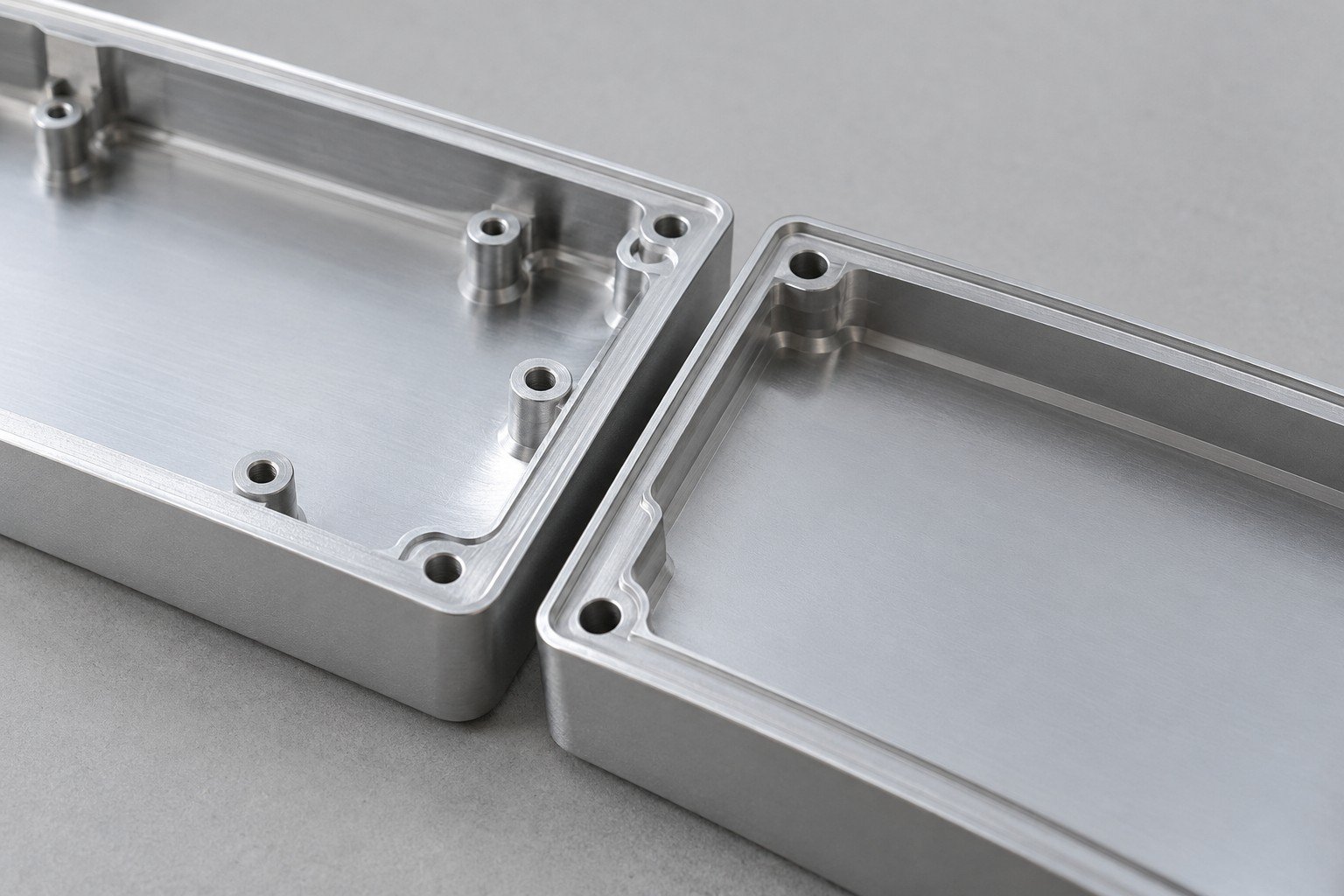
Use the coating supplier’s process evidence and your released drawing for the actual allowance.
For consumer electronics prototyping services, decide what the sample needs to prove: geometry, appearance, assembly or a defined functional check.
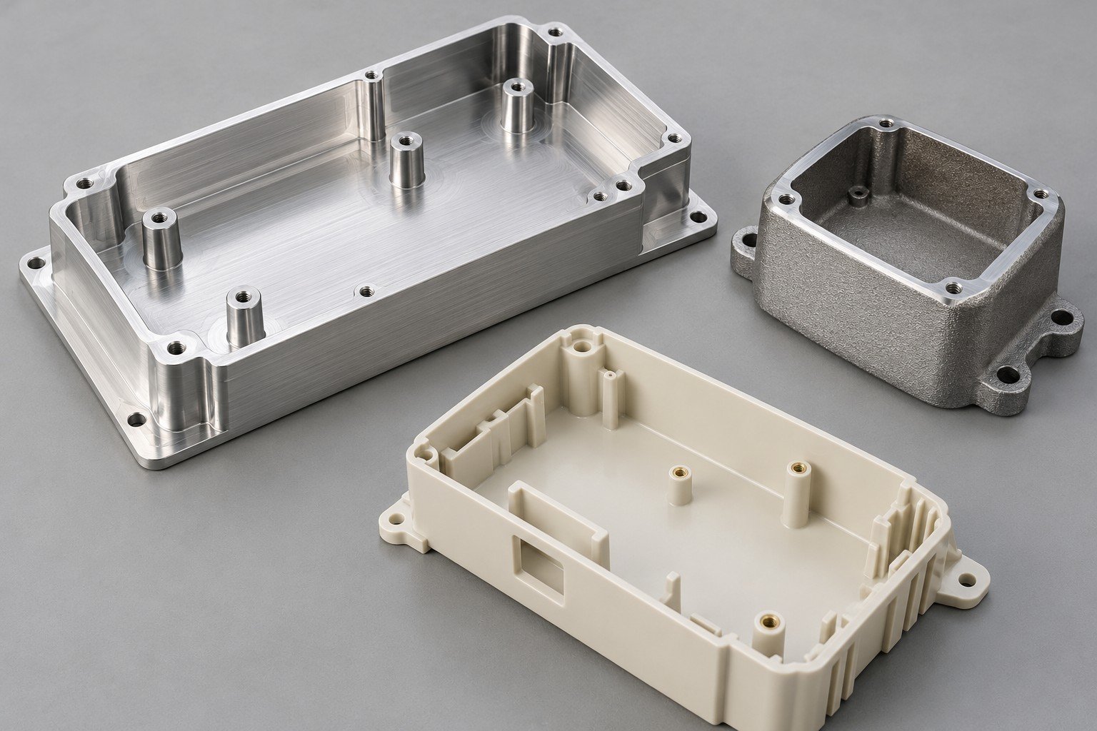
Define what your sample needs to demonstrate before choosing the prototype and production route.
| Your route | Useful review | Before your approval |
|---|---|---|
| CNC machining | Housing geometry and critical mating features | Tool access, thin walls and final finishing |
| Die cast consumer electronics housings | Repeat geometry with a reviewed tooling plan | Draft, parting lines, ejection, secondary features and agreed material |
| Sheet-metal fabrication | Formed covers, brackets and chassis details | Bend access, hardware, edges and visible seams |
| Plastic molding or printed prototypes | Alternative material and assembly concepts | Part condition differs by process; review your product requirements |
No universal tooling payback or minimum quantity is implied; review your geometry and expected demand.
For cosmetic finishing for electronics enclosures, replace subjective instructions such as “perfect finish” with an agreed visual standard.
Identify which faces the user sees and which are hidden.
Agree viewing distance, lighting and comparison method.
Confirm color, texture and acceptable variation.
Protect finished faces and keep mating components separated.
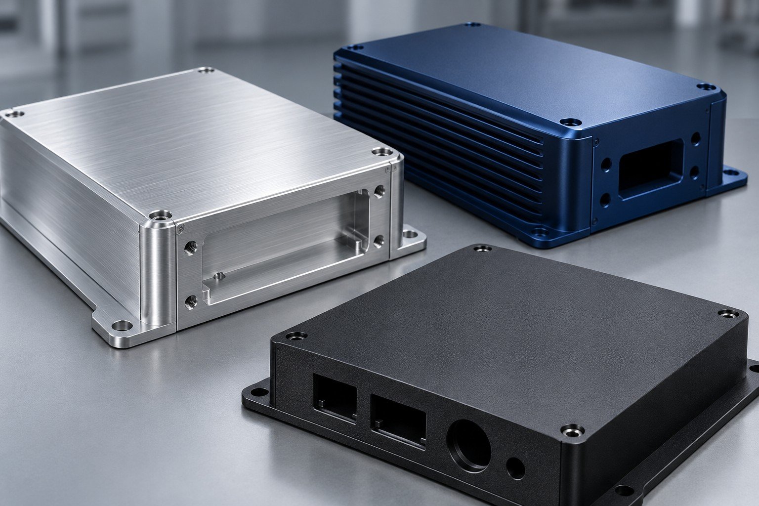
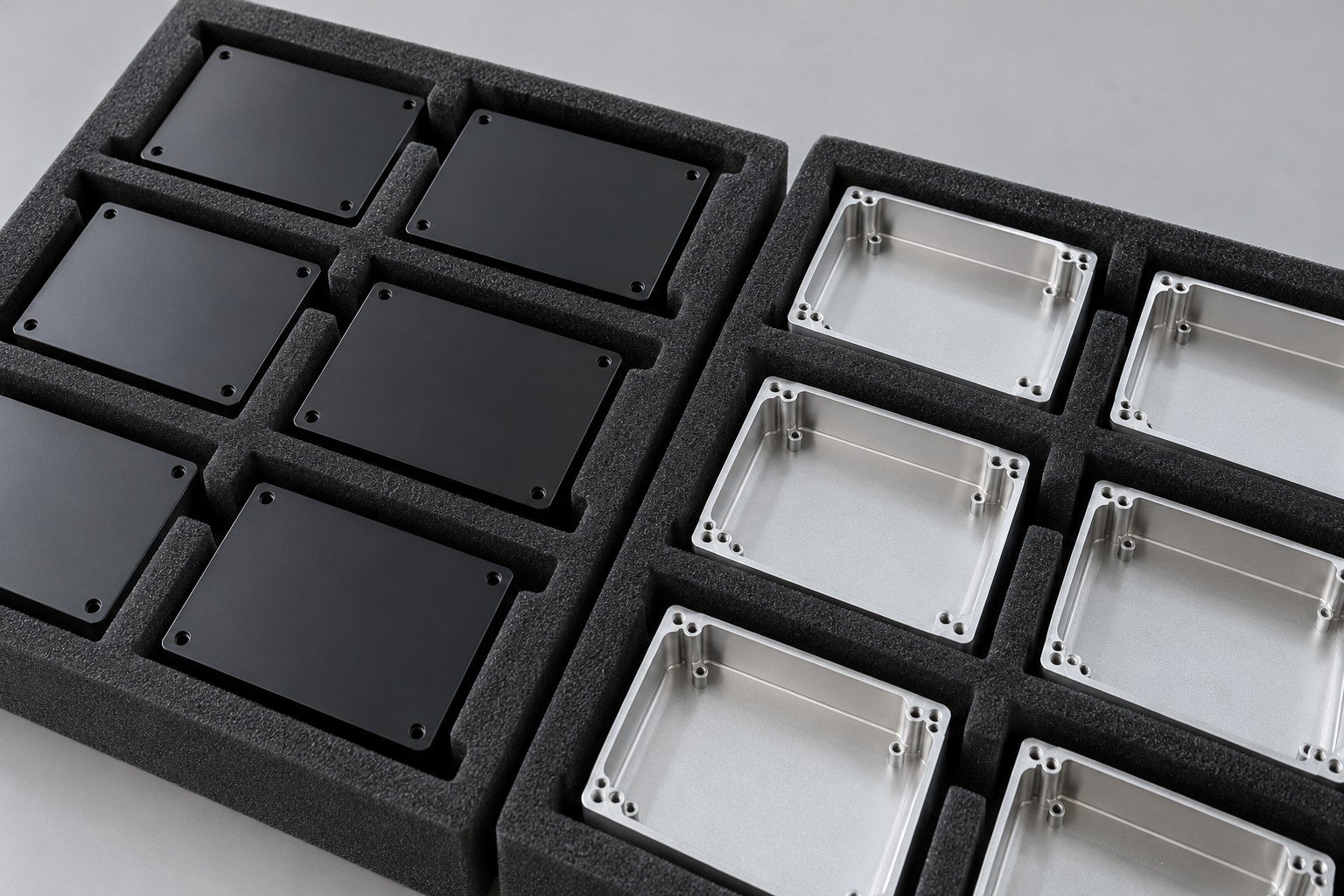
Confirm drawing revision and actual application.
Review material, geometry and manufacturing sequence.
Build the agreed sample and check defined interfaces.
Record accepted features, finish and required evidence.
Coordinate repeat scope, packing and delivery requirements.
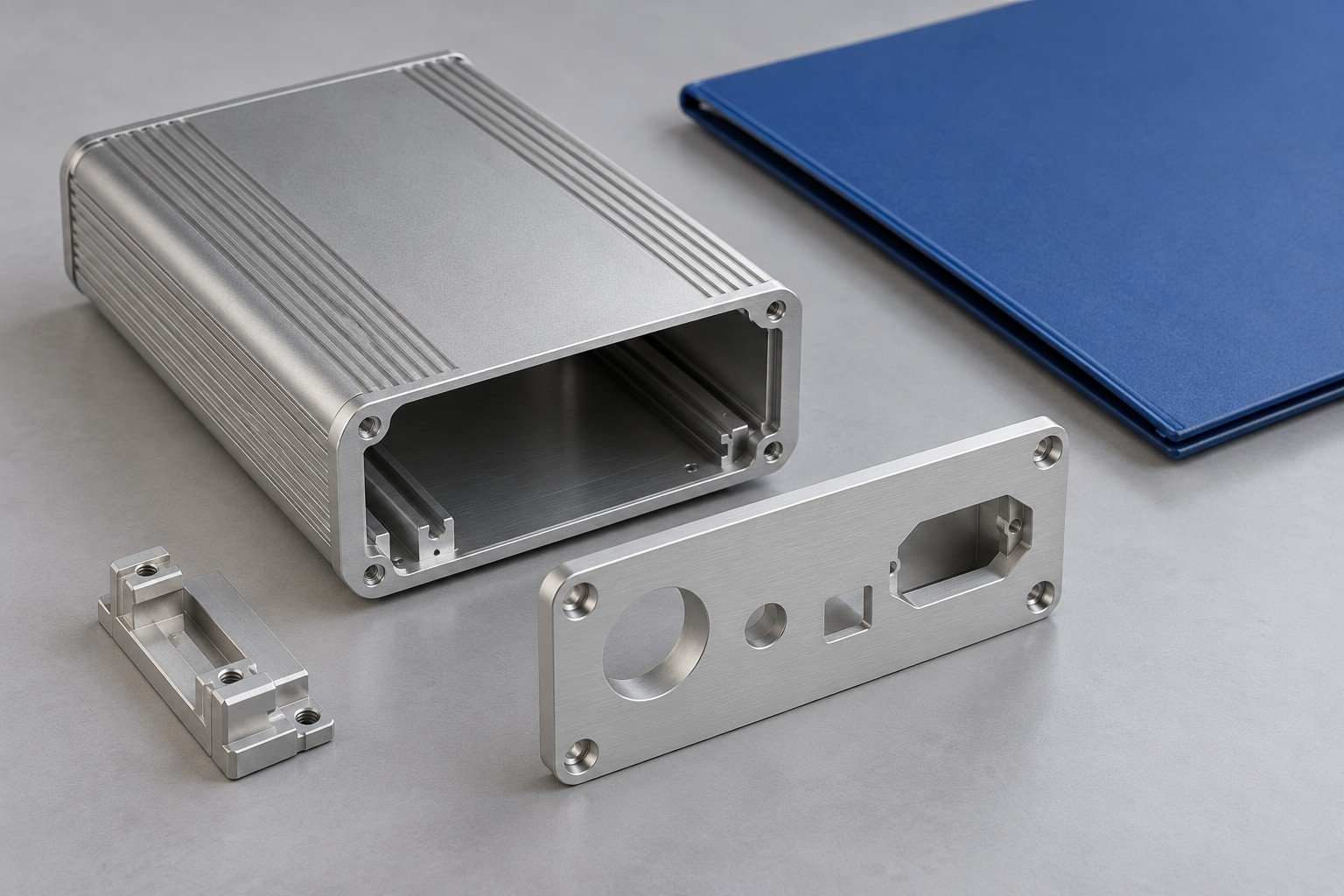
Mark visible zones on the drawing, share an approved color/texture sample and agree viewing conditions, defect criteria and packaging. Separate cosmetic approval from dimensional inspection.
Identify the acceptance condition on the released drawing. Review coating buildup, material conversion, masking and any post-finish machining with the supplier.
A prototype can answer selected design questions. Confirm tooling, material, finish and production acceptance separately when the manufacturing route changes.
Provide CAD, controlled drawing, material, finish and masking, cosmetic zones, mating-part information, trial/repeat quantities and required records.
Connect your appearance sample to an agreed finishing route.
Explore surface finishing →