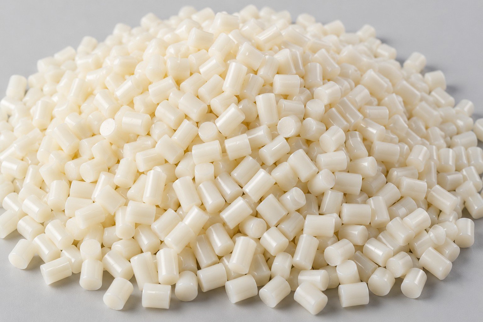
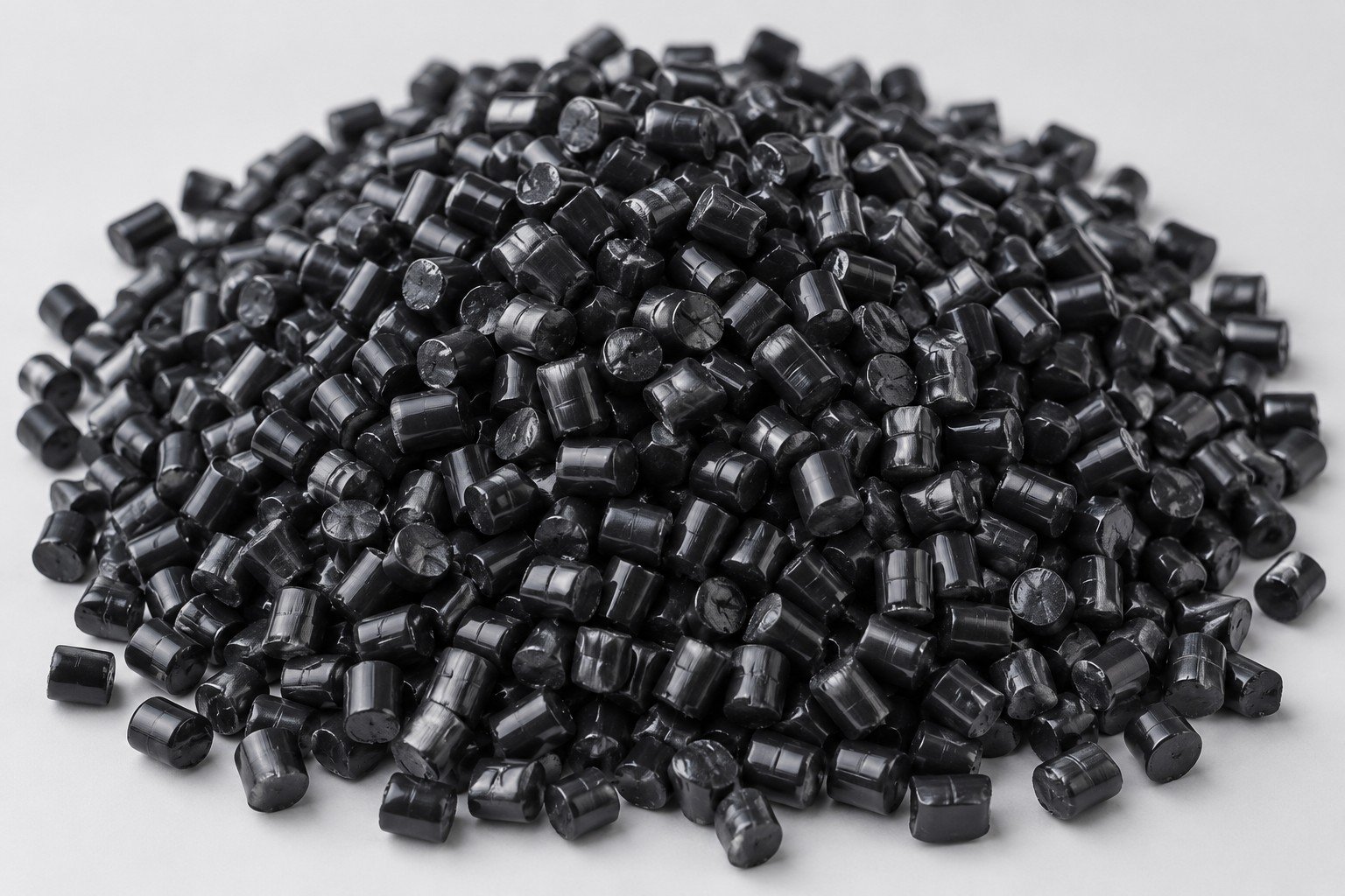
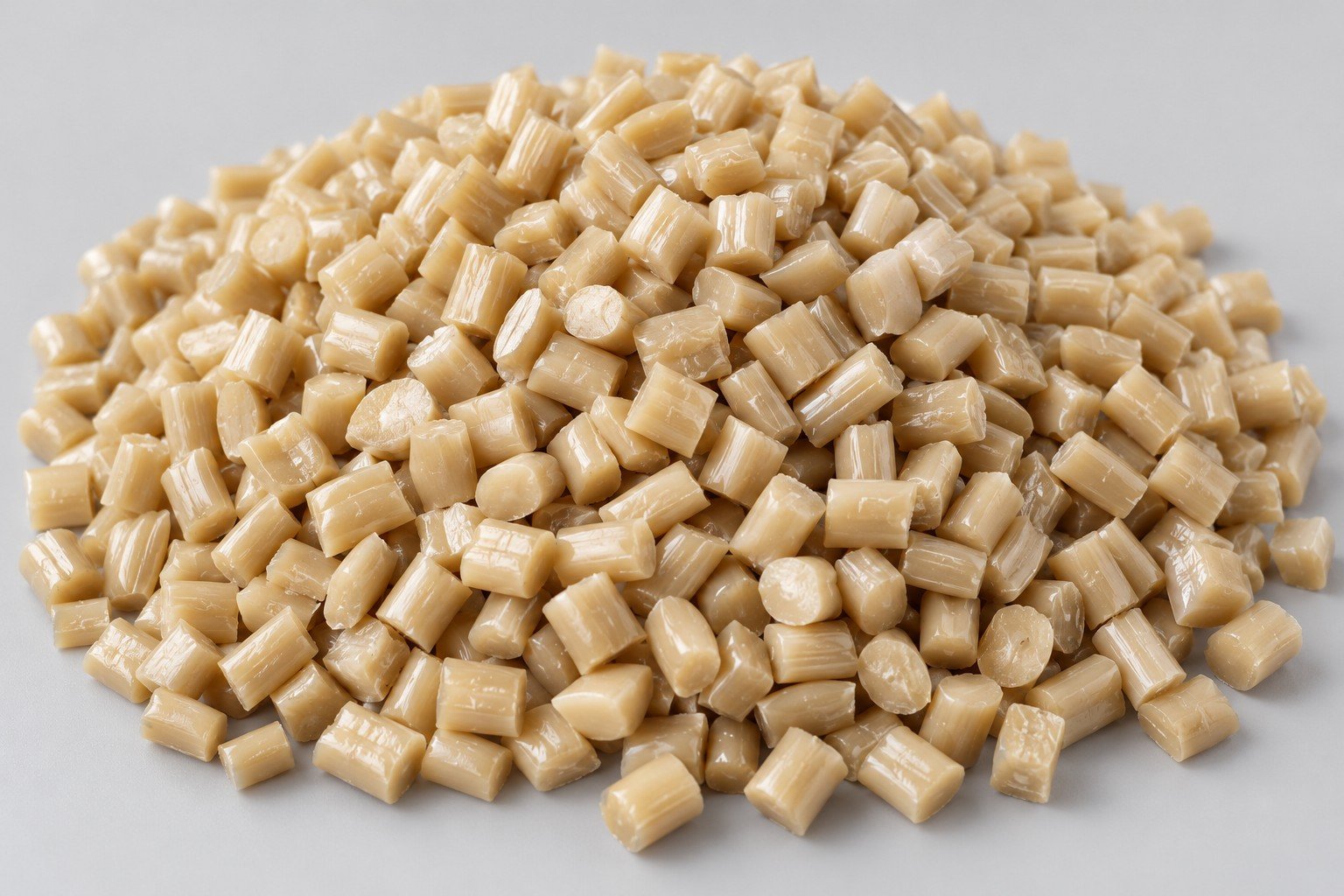
Injection Molding
Tooling and molding for your repeat plastic parts.
From prototype to production, coordinated manufacturing solutions for your custom parts.
View All Services →
Precision parts for your tight tolerances and complex geometry.
Tooling and molding for your repeat plastic parts.

Metal casting options for your part and production volume.

Cutting, forming and welding for your fabricated parts.

Custom profiles for your section, length and finish requirements.

Finishes for your appearance, corrosion and wear requirements.

Sub-assemblies and final builds for your production program.

Production tooling built around your process and volume.

Prototype parts to check fit, function and design.
DFM, process planning and production support for your project.
Inspection, documentation, inventory and delivery planning for your program.
Choose air- or liquid-cooling components around your thermal and mechanical requirements.

Manufacturing support for your cold plates, manifolds and cooling assemblies.

Find components for your power electronics, energy, laser and telecom application.

Components for your electronic systems.
Start with your functional and quality requirements.
Build around your operating environment.
From prototype to production, review material performance, manufacturability and cost for your part.
Review grade, temper and finish for your metal parts.
 AluminumStrength, weight and machining›
 Stainless SteelCorrosion and finish requirements›
 Carbon & Alloy SteelDiscuss grade and heat treatment›
 Tool SteelDiscuss tooling and wear needs›
 TitaniumReview grade and part geometry›
 Copper & Brass & BronzeDiscuss conductivity and machining›
Match your polymer to function, process and environment.
 ABSReview enclosure and molding needs›
 Polycarbonate (PC)Discuss clarity and impact needs›
 Nylon (PA)Review moisture and wear conditions›
 POM / AcetalReview fit and sliding features›
 PEEKDiscuss operating conditions›
 PTFEReview friction and chemical exposure›
 ULTEM / PEIDiscuss thermal and electrical needs›
Confirm grade availability and application requirements.
 Silicone / LSRDiscuss flexible component needs›
 TPU / TPEReview flexibility and processing›
 EPDMReview weathering and chemical exposure.›
 NBRReview oil and fuel exposure.›
 FKMReview temperature and chemical exposure.›
 G10 / FR4Review insulation and laminate needs›
 CompositesReview stiffness, weight and laminate.›Customer-Specified MaterialsConfirm your grade and requirements.›Other Specialty MaterialsDiscuss your application and grade.›
Practical guidance for your part geometry and material decisions.
Prepare your process, budget and sourcing questions.
Build your knowledge before production.
Learn who we are and how we operate.
Find our U.S. support team or start a conversation.
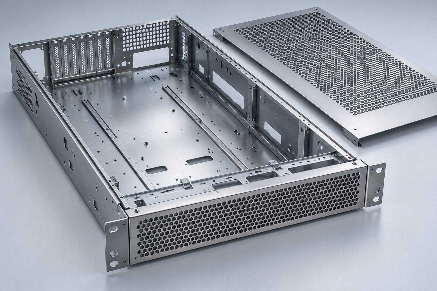
YOUR CHASSIS. YOUR RAILS. YOUR SERVICE SPACE.
Review your chassis, mounting brackets and cable-support parts around the installed assembly. When choosing a custom server chassis manufacturer, share the released drawing, mating hardware and acceptance requirements together.
State the allocated U height and actual usable depth.
Identify mating rail kits, rack ears and fastening access.
Reserve openings, connector space and service access.
Define protected contacts, appearance and sample evidence.
For your data center rack hardware manufacturer review, distinguish the fabricated component from complete server, rack and electrical-system approval.
Review formed edges, removable covers, standoffs and cable openings.
Your input: assembly envelope, material, thickness and released revision.
Match rack ears, locating slots and fastening faces to the actual mounting hardware.
Your input: mating rail model, hole pattern and installed loading requirements.
Identify cable-management brackets, support plates and protected connection areas.
Your input: routing, bend clearance, insulation interfaces and assembly sequence.
Manufacturing scope is confirmed from your part. Rack load, EMC, electrical safety and thermal performance need their own defined approval.
U height tells you the nominal vertical allocation. It does not confirm your chassis depth, rail-kit range, rear connector clearance or door access.
1U = 44.45 mm · zero baseline, 0–180 mm
Height = U × 44.45 mm. These are rack-space references, not finished chassis dimensions or LK MFG tolerances. Allowances and mounting details follow your selected equipment specification.
A nominal 19-inch interface does not establish the outside width of a cabinet or guarantee compatibility.
Reference: Vertiv rack catalogue · page6 installation units → Only unit geometry is used; no supplier load, cooling or delivery claim is transferred to your project.
For custom server mounting brackets, identify which surfaces locate the chassis and which fasteners only clamp it.
Share the mating rail drawing or approved interface dimensions. A product name alone may not define the installed geometry.
Review formed hardware →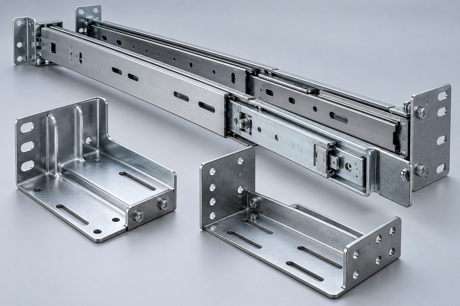
For server chassis sheet metal fabrication, review bend access, formed dimensions and joining before choosing the production route.
| Your part feature | Route to review | Decision for your drawing |
|---|---|---|
| Thin trays, covers and mounting ears | Laser cutting and forming | Thickness, bend orientation, hardware and edge requirements |
| Locating blocks or close mating faces | CNC machining | Datums, tool access and critical dimensions |
| Repeated lengthwise rail or support section | Extrusion plus secondary machining | Existing/new profile, cut length and end features |
| Multi-part frame or bracket group | Joining and assembly | Fixtures, distortion control and final mating checks |
Tooling investment, economical quantity and lead time require your geometry and order scope; no universal break-even quantity is implied.
State the governing material specification, thickness, finish and cosmetic faces. Confirm substitutions before manufacture.
Mark masked contacts, threads and mating surfaces. Define the required bonding verification with the assembly owner.
Review grade, bend geometry, hole pattern, coating and insulation interfaces. Ampacity, temperature rise and electrical safety cannot be inferred from a material certificate or appearance.
Material properties alone do not establish an assembly rating. Define electrical and mechanical acceptance separately.
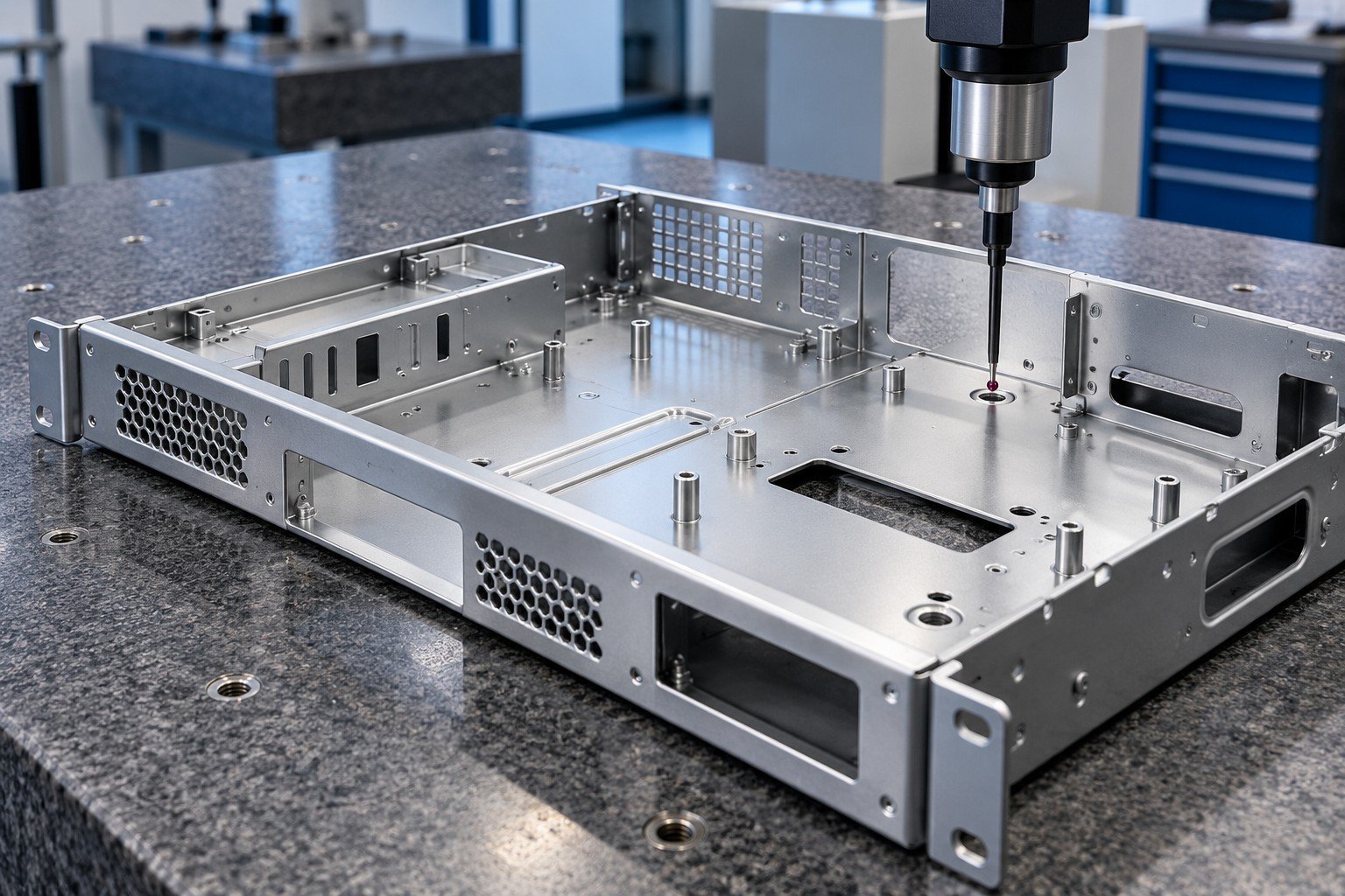
Released revision, mating dimensions and assembly configuration.
Rack ears, cover fit, fastener access and selected interfaces.
Agreed appearance sample, protected contacts and packing.
Required dimensions, sampling and agreed inspection records.
A dimensional report does not validate complete server performance, EMC, electrical safety or rack loading.
Review inspection documentation →No. Compare the nominal allocation with the actual chassis dimensions, rail kit, hole pattern and required clearances. Use your released interface specification.
Provide the CAD model, controlled drawing and revision, material and thickness, finish and masking requirements, trial and repeat quantities, mating hardware and required records.
Review the specified coating on mounting faces, holes, threads and bonding contacts. Confirm masking and final-condition acceptance before sample approval.
This page concerns manufactured components reviewed to your drawing. Complete-system design, ratings, certification and approval remain a separately defined project scope.