LK MFG

Author: LK MFG

  • Kegelsenkungen: Winkel, Zeichnungsangaben und Prüfungen

    Kegelsenkungen: Winkel, Zeichnungsangaben und Prüfungen

    Eine Kegelsenkung bietet einem Senkkopf-Verbindungselement eine konische Auflagefläche. Für Ihr Bauteil ist entscheidend, ob die ausgewählte Schraube in der vorgesehenen Höhe sitzt und ihr Kopf ausreichend abgestützt wird. Auch eine im CAD-Modell korrekt erscheinende Bohrung kann Rückfragen erfordern, wenn Winkel, Durchmesser, Senkseite oder der Zustand nach der Oberflächenbehandlung in der Zeichnung fehlen.

    Dieser Leitfaden erläutert die Angaben, die Sie in Ihre Zeichnung und Angebotsanfrage aufnehmen sollten. Er unterstützt die Konstruktionsprüfung; maßgeblich für die Fertigung bleiben die freigegebene Spezifikation des Verbindungselements und Ihre Zeichnung.

    Was ist eine Kegelsenkung?

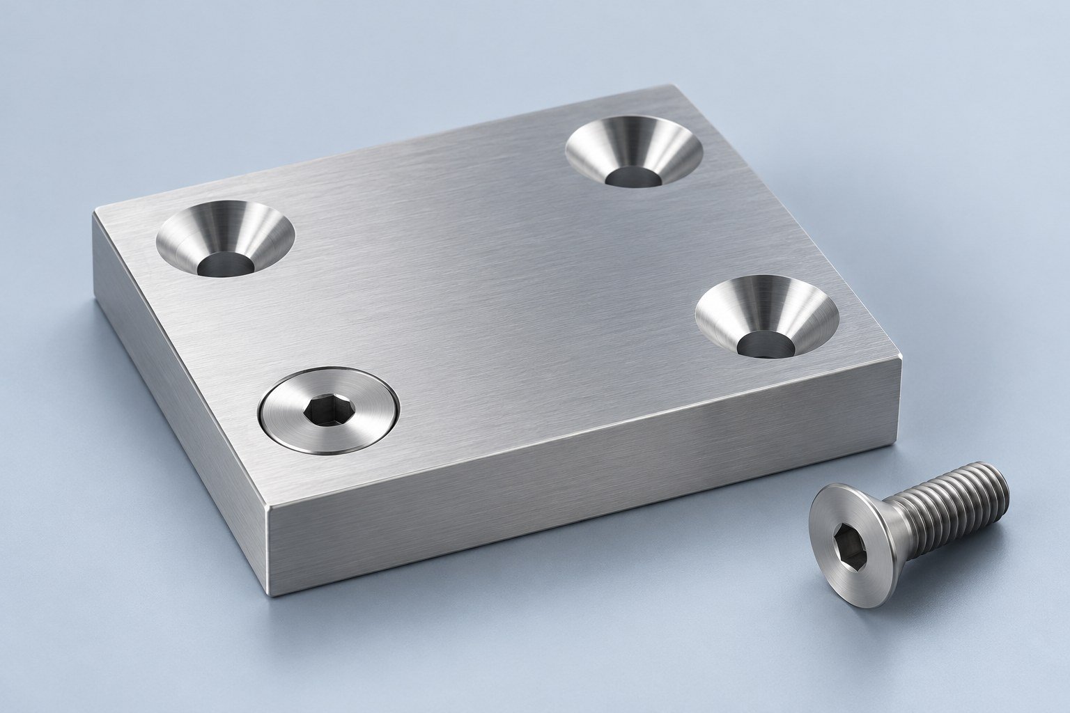
    Eine Kegelsenkung ist eine konische Erweiterung an der Öffnung einer Bohrung. Der Konus bildet die Auflagefläche für eine passende Senkkopfschraube oder einen passenden Senkniet. Eine Flachsenkung hat dagegen eine zylindrische Vertiefung mit ebenem Grund. Auch eine Fase zum Kantenbrechen kann konisch aussehen. Eine allgemeine Entgratungsangabe definiert jedoch keinen vollständigen Schraubenkopfsitz.

    Merkmal Form der Auflagefläche Erforderliche Zeichnungsangaben
    Kegelsenkung Konisch Bohrungsdurchmesser, größter Senkdurchmesser, eingeschlossener Winkel und Senkseite
    Flachsenkung Ebener Grund mit zylindrischen Wänden Bohrungsdurchmesser, Durchmesser und Tiefe der Vertiefung
    Kantenbruch Kleine Fase oder Rundung Zulässiger Kantenzustand; daraus darf nicht automatisch ein definierter Schraubensitz abgeleitet werden

    Stimmen Sie den Senkwinkel auf Ihr Verbindungselement ab

    Der Senkwinkel ist der gesamte eingeschlossene Winkel des Konus. Gängige Werkzeuge sind unter anderem mit 82° und 90° erhältlich. Der Werkzeughersteller Thürmer nennt 90° für übliche metrische Senkkopfschrauben und 82° für übliche zöllige Senkkopfschrauben. Nutzen Sie dies als Ausgangspunkt und prüfen Sie anschließend die tatsächliche Spezifikation des Verbindungselements. Sonderausführungen können einen anderen Winkel erfordern.

    Wählen Sie den Winkel nicht allein anhand des Gewindedurchmessers. Stellen Sie Ihrem Fertigungsteam die Schraubenbezeichnung oder Lieferantenzeichnung sowie Angaben zu Beschichtung und besonderen Kopfanforderungen bereit. Bei nicht übereinstimmenden Winkeln verändert sich der Kontakt zwischen Kopf und Sitz. Ein größerer Senkdurchmesser allein stellt keine passende Auflage sicher.

    Definieren Sie die Bohrung mit vollständigen Zeichnungsangaben

    Das CAD-Modell beschreibt die Form. Die gelenkte Zeichnung legt Maße und Abnahmeanforderungen fest. Geben Sie Folgendes an:

    • Den Bohrungsdurchmesser mit dem vorgesehenen Spiel für das Verbindungselement sowie die Angabe, ob die Bohrung durchgehend oder als Sackloch ausgeführt wird.
    • Den größten Senkdurchmesser und den gesamten eingeschlossenen Winkel mit den jeweiligen Toleranzen.
    • Die zu senkende Fläche, insbesondere wenn beide Seiten als Eintrittsseite verstanden werden könnten.
    • Anzahl und Positionen gleichartiger Merkmale.
    • Die erforderliche Kopfposition: bündig, unterhalb der Oberfläche oder ein anderer festgelegter Zustand.
    • Werkstoff, Oberflächenbehandlung und ob die Abnahme vor oder nach dieser Behandlung erfolgt.

    Eine schematische Angabe wie „⌀6,6 DURCH; Kegelsenkung ⌀12 × 90°, diese Seite“ veranschaulicht die benötigten Informationen. Diese Beispielmaße sind keine Empfehlung für eine bestimmte Schraube. Leiten Sie die Werte aus Ihrem tatsächlichen Verbindungselement, dem Bauteilaufbau und den technischen Anforderungen ab. Verwenden Sie Symbole und Darstellung gemäß Ihrer Zeichnungsnorm.

    Nutzen Sie die Tiefenberechnung als geometrische Kontrolle

    Für einen idealen konischen Sitz bezeichnet D den größten Senkdurchmesser, d den zylindrischen Bohrungsdurchmesser und θ den gesamten eingeschlossenen Winkel. Die axiale Höhe der konischen Erweiterung beträgt:

    h = (D − d) / [2 × tan(θ / 2)]

    Bei D = 12 mm, d = 6,6 mm und θ = 90° ergibt sich beispielsweise h = 2,7 mm. Dies ist eine geometrische Veranschaulichung, keine Einstellung für die Werkzeugzustellung und keine Zusage einer passenden Schraubenauflage. Eine abgeflachte Werkzeugspitze, die tatsächliche Kopfgeometrie, Kantenbrüche und die Oberfläche können das Ergebnis beeinflussen. Die bestimmenden Zeichnungsmaße bleiben maßgeblich; vermeiden Sie widersprüchliche Angaben zu Durchmesser und Tiefe.

    Prüfen Sie Restmaterial und benachbarte Merkmale

    Vergleichen Sie die Geometrie des konischen Sitzes mit der örtlichen Wanddicke. Nähert sich die Senkung der gegenüberliegenden Fläche, sollten Sie mit der zuständigen Konstruktion die verbleibende Abstützung und das Risiko eines Durchbruchs prüfen. Bei dünnem Blech kann ein anderes Verbindungselement oder eine umgeformte Kontur anstelle einer tiefen spanend erzeugten Kegelsenkung erforderlich sein. Solche Alternativen müssen freigegeben werden; sie sind keine ohne Weiteres austauschbaren Fertigungsausführungen.

    Prüfen Sie außerdem Randabstände, benachbarte Bohrungen, Biegungen, Taschen sowie den Platzbedarf für Werkzeug und Verbindungselement. Eine übersichtliche Draufsicht kann einen Konflikt mit einer Tasche auf der Rückseite verdecken. Eine Schnittansicht kann diesen Zusammenhang leichter prüfbar machen.

    Vereinbaren Sie die Prüfung des Schraubensitzes

    Die Prüfung sollte den Abnahmekriterien der Zeichnung folgen. Größter Senkdurchmesser, eingeschlossener Winkel und Position beschreiben unterschiedliche Eigenschaften des Merkmals. Eine Musterschraube kann bei vereinbarter Prüfung zeigen, wie der Kopf in der Baugruppe sitzt. Sie weist jedoch nicht unabhängig jede Maßanforderung nach.

    Legen Sie für eine funktionale Erstmusterprüfung das tatsächliche Verbindungselement und den zu prüfenden Bauteilaufbau fest. Geben Sie an, ob die Bündigkeit nach der Beschichtung geprüft wird, und definieren Sie einen zulässigen Rückstand oder Überstand. Wenn Oberflächenschäden, Grate oder Rattermarken die Montage beeinflussen würden, klären Sie den erforderlichen Oberflächenzustand vor Fertigungsbeginn.

    Welche Angaben gehören in Ihre Angebotsanfrage?

    Senden Sie das aktuelle CAD-Modell mit Zeichnungsrevision, Werkstoff und Oberflächenbehandlung, Erst- und Wiederholmengen, die Spezifikation des Verbindungselements sowie die entscheidenden Anforderungen an Sitz und Prüfung. Kennzeichnen Sie offene Entscheidungen, statt Ihrem Lieferanten deren Auslegung zu überlassen. So erhält Ihr Team eine klarere Grundlage für den Angebotsvergleich und die Freigabe der ersten Fertigung.

    Weitere Informationen finden Sie in der RFQ-Checkliste für CNC-Bearbeitung und der Übersicht zur CNC-Bearbeitung.

    Fragen vor der Freigabe

    Ist eine Kegelsenkung dasselbe wie eine Fase?

    Eine Kegelsenkung kann mit einem konischen Schneidwerkzeug hergestellt werden. Hier dient sie jedoch als festgelegter Sitz für ein Verbindungselement. Aus einer allgemeinen Fasen- oder Kantenbruchangabe dürfen dessen Durchmesser, Winkel und Kopfposition nicht automatisch abgeleitet werden.

    Kann ich 82° oder 90° nach dem Aussehen auswählen?

    Nein. Prüfen Sie die Spezifikation des Verbindungselements und den erforderlichen eingeschlossenen Winkel. Ähnlich aussehende Köpfe und Werkzeuge belegen keine Übereinstimmung ihrer Winkel.

    Beweist ein bündiger Kopf, dass die gesamte Bohrung korrekt ist?

    Nein. Der Sitz ist eine einzelne Funktionsprüfung. Ihre Zeichnung kann zusätzlich die maßliche Prüfung von Durchmesser, Winkel, Position und weiteren Merkmalen verlangen.

    Technische Quellen

  • Thermoplastic vs Thermoset: Material Decisions for Your Part

    Thermoplastic vs Thermoset: Material Decisions for Your Part

    Choosing thermoplastic vs thermoset starts with what your part must do, how it will be made and what must remain stable in service. A material-family name alone cannot confirm temperature capability, chemical resistance or fit. Define those requirements before selecting a resin grade or committing to tooling.

    This guide compares the two families for a custom-part review. It complements the thermoplastic injection molding service and elastomer and specialty material options; it does not replace a grade-specific datasheet or application testing.

    The practical difference: cooling versus curing

    A thermoplastic softens with heat and becomes firm again as it cools. Its structure allows another forming cycle within an appropriate processing window. A conventional thermoset develops a crosslinked network during cure. After that reaction, reheating does not return it to a melt that can be molded again in the same way.

    For your project, that distinction affects the manufacturing route and what happens to process scrap. It does not establish which finished part is stronger, cheaper or more durable. Those comparisons need a specified grade, geometry, production process and test conditions.

    Compare the decisions that affect your part

    Your decision Thermoplastic review Thermoset review
    How the shape is established Heat and forming, followed by cooling; the route depends on the resin and part. A curing reaction establishes the network; review the selected molding or laminate route.
    Examples to investigate PP, ABS, PC and PA grades for different functions. Epoxy-based systems and cured silicone systems for different functions.
    What to specify Exact grade, fillers, conditioning and relevant performance tests. Exact formulation or laminate designation, cure requirements and relevant performance tests.
    End-of-life question Ask whether the actual grade and waste stream can be collected and reprocessed. Do not assume conventional melt recycling; investigate an available, suitable recovery route.

    Start with the service conditions

    Describe the environment your part will experience: continuous and occasional heat, applied load, chemicals, moisture, sunlight and repeated movement. Identify which conditions occur together. An unloaded short heat exposure is a different requirement from a loaded assembly operating for an extended period.

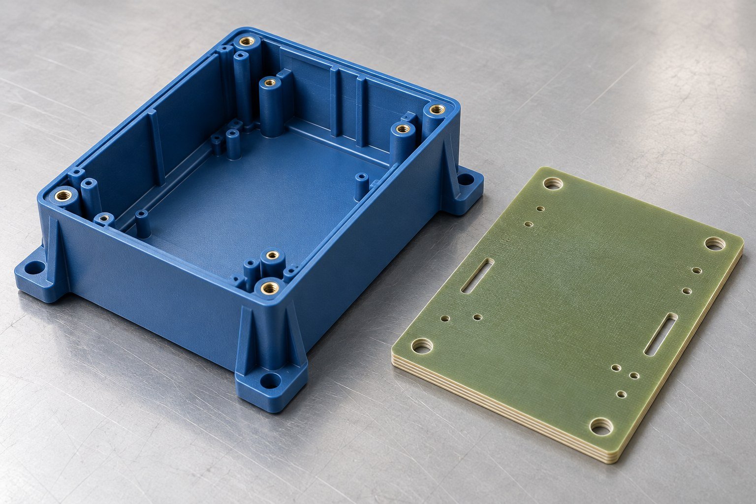
    Then define the outcome you need to preserve. For an enclosure, it may be assembly fit and the position of a sealing surface. For an insulating plate, it may be dimensional stability and the specified electrical performance. Share the applicable test method and acceptance criteria rather than asking for the “best plastic.”

    Match the family to a manufacturing route

    Thermoplastic injection molding is one route for repeat molded parts; extrusion and machining of suitable stock shapes answer different geometry and quantity needs. Thermoset processing depends on the particular system. A cured laminate machined into a plate should not be treated as interchangeable with an injection-molded resin.

    Discuss the actual route before freezing your drawing. Ask which surfaces establish assembly position, which features need inspection and where a design change could simplify manufacture. If you are comparing a prototype with a later molded part, record the material and process differences so that a successful prototype is not mistaken for complete production validation.

    Do not group every flexible material together

    Flexible behavior does not identify a material as thermoplastic. A thermoplastic elastomer and a cured rubber can both feel flexible while belonging to different processing families. When reviewing a seal, grip or compliant interface, provide the material designation and function instead of specifying only “rubber” or a color.

    Use the TPU and TPE material page to frame a thermoplastic-elastomer discussion, and the silicone and LSR molding information for a separate cured-silicone review. Confirm the final formulation and processing scope for your application.

    Ask a specific recycling question

    Being remeltable does not guarantee that a used part will be recycled. Separate the technical possibility from the collection and processing route available for your actual material stream. Ask about the exact grade, additives, contamination and the requirements governing any proposed reuse.

    For a purchasing decision, request a documented answer for the proposed material and program. Do not turn a broad material-family description into a recycling promise for your finished product.

    Prepare a useful material comparison package

    • Part definition: CAD, drawing revision, critical interfaces and inspection requirements.
    • Operating environment: heat exposure, load, fluids and other relevant conditions.
    • Material scope: required grade or candidate grades, fillers, color and documentation needs.
    • Manufacturing plan: prototype purpose, expected order quantities and the process routes being compared.
    • Acceptance: tests and evidence needed before you approve the material and finished part.

    Keep unresolved requirements visible. A material comparison is useful when it explains what has been verified, what still needs testing and who approves the final choice. For a broader review, see material and process selection.

    Your thermoplastic and thermoset questions

    Is a thermoset always better at high temperature?

    No family label establishes your allowable service temperature. Compare the proposed grades under the relevant load, exposure duration and acceptance conditions.

    Can a cured thermoset be melted and molded again?

    A conventional cured thermoset cannot be remelted for ordinary molding in the same way as a thermoplastic. Discuss any proposed recovery method separately.

    Does this comparison identify a drop-in replacement?

    No. A substitution needs a review of the specific grade, process, drawing and application. Preserve the approval record for any change.

  • Jigs vs Fixtures: Workholding Decisions for Your Part

    Jigs vs Fixtures: Workholding Decisions for Your Part

    Your jig and fixture requirements should start with the operation, the part revision and the surfaces that establish position. A useful workholding brief explains what must stay accessible, what must be protected and how your team will accept the completed tooling.

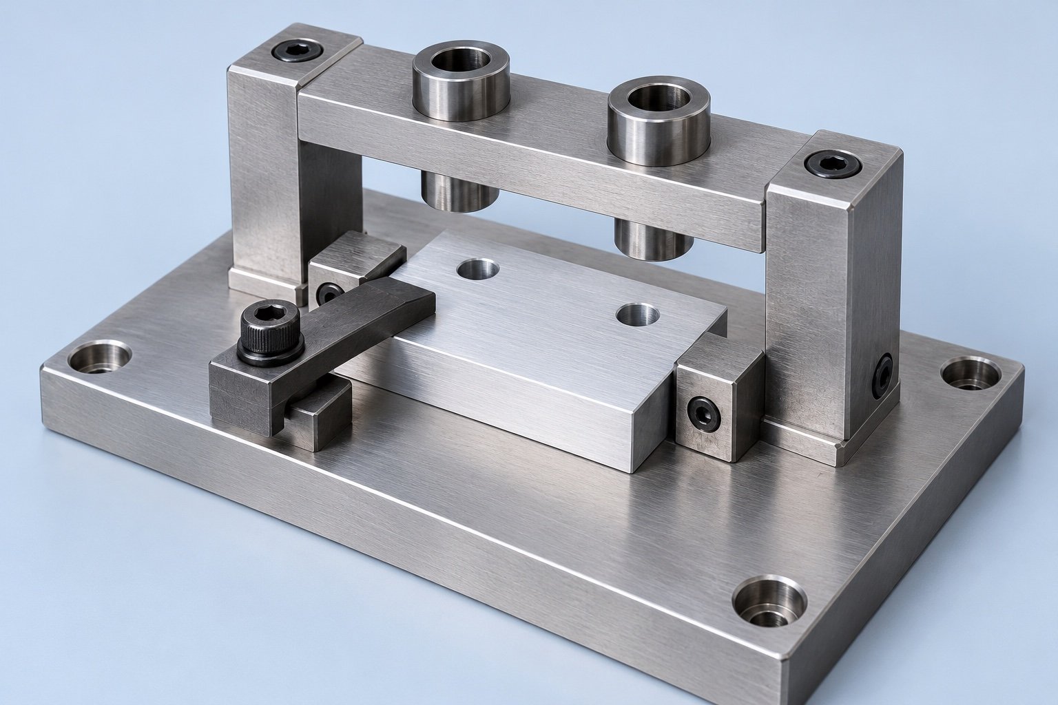
    A jig usually locates and holds a workpiece while also guiding a cutting tool. A fixture locates and holds the workpiece while the machine or another system controls the tool path. For example, a drill jig can use guide bushings; a milling fixture leaves the cutter path to the machine. This distinction is described in KEYENCE’s explanation of manufacturing and inspection fixturing.

    Decide what the tooling needs to control

    Begin with the job your tooling must perform rather than requesting a particular shape. Your team may need to drill a repeated hole pattern, expose several faces for milling, support an assembly while fasteners are installed, or present a part consistently for inspection. Each task creates a different access and acceptance problem.

    Question Jig example Fixture example
    What guides the tool? A drill bushing physically guides a drill. The machine controls cutter movement.
    What needs access? The tool must enter and clear the guide. The planned cutter, probe or assembly tool must reach the required features.
    What should your brief include? Hole requirements, tool details and bushing service needs. Setup orientation, locating features and the required working envelope.

    The label alone does not define the design. Attach a marked drawing or setup sketch showing your intended operation and ask the tooling supplier to identify any assumptions before manufacture.

    Separate locating, support and clamping

    Locators establish the part’s position. Supports provide a reaction beneath the workpiece, while clamps keep it seated. Carr Lane’s fixture design principles explain the relationship between locating and clamping and the need to avoid redundant location. Its work-support guidance also describes how inadequate support can allow cutting forces to deflect a part.

    For your review, identify which drawing surfaces or holes are the references, which incoming features may vary and where a clamp may contact the part. Do not leave a supplier to infer that a convenient raw edge is a functional datum. If a cosmetic face cannot be marked, say so and agree how it will be protected.

    Review access before approving the model

    Ask for a setup view with the workpiece, clamps and intended tools shown together. Check the approach to each required feature, the space needed to change a tool and the route for loading and removing the part. An attractive empty fixture model can conceal a difficult loaded setup.

    Include the inspection method in that discussion. A feature that is easy to machine may be difficult to probe with the part clamped. Your acceptance plan should state which checks happen in the fixture and which happen after removal. Tooling approval should not silently replace the finished-part drawing requirements.

    Choose materials around the actual environment

    Give the supplier the expected coolant, cleaning method, contact surfaces and any temperature or chemical exposure. Identify parts that should be replaceable, such as contact pads, locating elements or drill bushings, and request an agreed spare-parts list where maintenance matters.

    Machined metal, polymer contact elements and printed components may each have a role, depending on load, wear, environment and the required accuracy. A material name by itself is not enough to approve a production tool. Ask what evidence supports the proposed material for your specific operation. Any change to a locating or contact element should trigger a review of its effect on the part.

    Use a trial to answer a specific question

    Consider an illustrative bracket project. Your drawing identifies the mounting face and two holes as functional references, but the incoming blank has a variable outer profile. The tooling review should clarify how the bracket is located without relying on that profile, where clamping is permitted and whether the cutter can reach the required faces.

    A useful trial then checks those agreed questions with representative parts. Record loading orientation, seating checks, access problems and the agreed measurement results. If several incoming conditions are permitted, identify which ones the trial represents. This example is a review method, not a promised tolerance, cycle time or production result.

    Send a complete jig and fixture RFQ

    • Current part CAD and drawing, including revision and relevant datums.
    • The operation, machine or workstation interface, and available envelope.
    • Incoming part condition, permitted variation and areas requiring protection.
    • Expected use, loading method and any handling constraints.
    • Tool, probe, fastener or assembly access that must remain available.
    • Acceptance checks, required records and maintenance expectations.

    If an input is undecided, flag it explicitly. Separate the requirements you have approved from proposals you want the supplier to evaluate. Your existing CNC machining RFQ checklist can help organize the drawing package; the tooling brief adds the setup and workholding requirements.

    Questions to settle before ordering

    Does every CNC setup need a custom fixture?

    Discuss standard workholding first, then identify the access, support or repeat-loading problem that remains. Ask the supplier to explain why custom tooling is appropriate for your part and scope.

    Can a printed component replace metal tooling?

    That requires an application-specific review. State the operating conditions and acceptance requirements, then evaluate the proposed component and validation plan rather than approving a substitution from a material label.

    What should accompany delivery?

    Agree the fixture revision, setup instructions, acceptance record and any replaceable-component information before the order. Keep these connected to the part revision so a later drawing change can be reviewed against the correct tool.

  • Countersunk Holes: Angles, Drawing Callouts and Design Checks

    Countersunk Holes: Angles, Drawing Callouts and Design Checks

    A countersunk hole gives a flat-head fastener a conical seat. For your part, the useful question is whether the selected screw will sit at the intended height, with enough material supporting its head. A hole that looks correct in CAD can still need clarification if the drawing leaves out the angle, diameter, seating side or finish condition.

    This guide explains the decisions to include in your drawing and RFQ. It is a design-review aid; your approved fastener specification and drawing control the manufactured feature.

    What is a countersunk hole?

    A countersunk hole has a conical enlargement at its opening. The cone provides a seat for a compatible countersunk screw or rivet. A counterbore has a cylindrical recess with a flat bottom. An edge-breaking chamfer may also look conical, but a general deburring note does not fully define a fastener seat.

    Feature Seat shape What your drawing should clarify
    Countersink Conical Hole diameter, major diameter, included angle and seating side
    Counterbore Flat bottom with cylindrical walls Hole diameter, recess diameter and recess depth
    Edge break Small chamfer or radius Permitted edge condition; do not assume it also defines a screw seat

    Match the included angle to your fastener

    The countersink angle is the full included angle of the cone. Common tooling includes 82° and 90° options. Tool manufacturer Thürmer identifies 90° with common metric countersunk screws and 82° with common inch countersunk screws. Treat that as a starting point, then verify the actual fastener specification. Special fasteners can require a different angle.

    Do not select the angle from the thread diameter alone. Give your manufacturing team the screw designation or supplier drawing, along with any coating or special head requirement. An angle mismatch changes how the head contacts the seat; increasing the diameter alone does not establish compatible seating.

    Define the hole with a complete drawing callout

    Your CAD model communicates shape, while the controlled drawing communicates the dimensions and acceptance requirements. Include:

    • The clearance-hole diameter and whether the hole is through or blind.
    • The countersink major diameter and full included angle, with the applicable tolerances.
    • The face receiving the countersink, especially when either side could be interpreted as the entry face.
    • The number and locations of matching features.
    • The required head position: flush, below the surface or another specified condition.
    • The material, finish and whether acceptance applies before or after that finish.

    A schematic note such as “⌀6.6 THRU; countersink ⌀12 × 90°, this face” illustrates the pieces of information. Those example dimensions are not a recommendation for a particular screw. Choose values from your actual fastener, stack-up and engineering requirements. Follow your drawing standard for symbols and presentation.

    Use depth calculations as a geometry check

    For an ideal conical seat, let D be the major diameter, d the cylindrical hole diameter and θ the full included angle. The axial height of the conical enlargement is:

    h = (D − d) / [2 × tan(θ / 2)]

    For example, with D = 12 mm, d = 6.6 mm and θ = 90°, h = 2.7 mm. This is a geometric illustration, not a cutter-depth setting or a guaranteed fastener fit. A cutter tip flat, a fastener’s head geometry, edge breaks and surface finish can affect the real result. Keep the drawing’s defining dimensions authoritative instead of adding conflicting diameter and depth requirements.

    Check remaining material and nearby features

    Compare the conical-seat geometry with the local wall thickness. If the seat approaches the opposite face, review the remaining support and any risk of breakthrough with your engineer. Thin sheet may need a different fastener or a formed feature rather than a deep machined countersink. These alternatives require approval; they are not interchangeable manufacturing substitutions.

    Also review edge distance, adjacent holes, bends, pockets and the access needed for the tool and fastener. A clear top view alone may hide a conflict with a pocket on the reverse side. A section view can make that relationship easier to inspect.

    Agree how the seat will be checked

    Inspection should follow the drawing’s acceptance criteria. Major diameter, included angle and location describe different aspects of the feature. A sample screw can help demonstrate assembly seating when that check is agreed, but it does not independently verify every dimensional requirement.

    For a functional first article, identify the actual fastener and mating stack used for review. Specify whether flushness is checked after coating, and define any permitted recess or protrusion. If surface damage, burrs or chatter marks would affect the assembly, make the required surface condition clear before production.

    What to include in your countersunk-part RFQ

    Send the current CAD model and drawing revision, material and finish, initial and repeat quantities, fastener specification, and the critical seating and inspection requirements. Highlight unresolved choices rather than leaving your supplier to infer them. That gives your team a clearer basis for comparing quotations and approving the first build.

    For related review inputs, see the CNC machining RFQ checklist and CNC machining service overview.

    Questions to resolve before release

    Is a countersink the same as a chamfer?

    A countersink can be produced with a conical cutting tool, but its role here is a specified fastener seat. A general chamfer or edge-break note should not be assumed to define that seat’s diameter, angle and head position.

    Can I choose 82° or 90° by appearance?

    No. Check the fastener specification and the required included angle. Similar-looking heads and tools are not evidence that their angles match.

    Does flush seating prove that the whole hole is correct?

    No. Seating is one functional check. Your drawing may also require dimensional verification of diameter, angle, location and other features.

    Technical references

  • كيفية اختيار مادة لجزء التصنيع باستخدام الحاسب الآلي الخاص بك

    قارن بين الوظيفة، وعملية التصنيع، والتشطيب النهائي، والوثائق المطلوبة قبل اعتماد تصميمك.

    ابدأ بتحديد الوظيفة الأساسية التي يجب أن تؤديها القطعة.

    قبل اختيار سبيكة مألوفة، دوّن الأحمال، ودرجة حرارة التشغيل، وأسطح التلامس، وبيئة العمل، والعمر الافتراضي المتوقع للقطعة. حدد المتطلبات الجوهرية (الأساسية) وتلك التي تُعد مجرد تفضيلات؛ فقد تكون المادة قوية ولكنها غير مناسبة إذا كانت عوامل الوزن، أو التآكل، أو الاهتراء، أو الاستقرار الأبعادي هي المحددات الرئيسية للتطبيق.

    اختر قائمة مختصرة من المواد المناسبة لعملية التصنيع الخاصة بك.

    بالنسبة للمواد المخصصة للتشغيل الآلي (CNC)، ضع في اعتبارك سهولة الوصول إلى تفاصيل القطعة، وسماكة الجدران، وخطر التشوه، وحالة المادة الخام الموردة. تختلف اعتبارات المعالجة بين الألومنيوم، والفولاذ المقاوم للصدأ، واللدائن الهندسية، وغيرها من فئات المواد. أما في حالة القولبة بالحقن، فيجب تقييم درجة الراتنج (المادة البلاستيكية) وشكل القطعة المصبوبة معاً؛ فالنموذج الأولي البلاستيكي المُصنّع آلياً لا يعكس بالضرورة الأداء الفعلي للقطعة المنتجة بالقولبة.

    قارن التكلفة الإجمالية للقطعة، وليس فقط سعر المادة الخام.

    اطلب من شريكك في التصنيع مراجعة وقت التشغيل الآلي، والأدوات، ونسبة الهالك، والتشطيب النهائي، والفحص، وكمية الطلب، إلى جانب تكلفة المواد الخام. إذا كانت المادة الأرخص سعراً تتطلب عمليات إضافية أو تؤدي إلى زيادة نسبة القطع المرفوضة، فقد تكون التكلفة النهائية للمكون أعلى. قارن عروض الأسعار بناءً على نفس مراجعة الرسم الهندسي، ومتطلبات التشطيب، ومعايير الفحص.

    حدد الدرجة (النوع)، والحالة، ومتطلبات التحقق.

    اذكر الدرجة المطلوبة، أو حالة المعالجة (مثل الصلابة أو المعالجة الحرارية) حيثما ينطبق ذلك. أدرج التفاوتات الوظيفية ومتطلبات التشطيب على الرسم الهندسي. إذا كنت بحاجة إلى شهادات المواد، أو إمكانية تتبع الدفعة الإنتاجية، أو وثائق امتثال محددة، فحدد ذلك قبل طلب عرض السعر للتأكد من توفرها وتحديد نطاق العمل.

    أرسل ملخصاً فنياً جاهزاً لاتخاذ القرار.

    شارك ملفات التصميم بمساعدة الحاسوب (CAD) والرسومات الهندسية، والكمية المستهدفة، وبيئة العمل، والأبعاد الحرجة، وأي بدائل مقبولة. اطلب مقارنة المفاضلة بين خيارين أو ثلاثة بدائل محتملة بدلاً من البحث عن “أفضل مادة على الإطلاق”. يتطلب الاختيار النهائي مراجعة دقيقة تتوافق مع متطلبات التطبيق وخطة التحقق من الجودة.

    استكشف المواد المناسبة لقطعتك · ناقش متطلبات التصنيع الخاصة بك

  • قائمة مراجعة RFQ الخاصة بالتصنيع باستخدام الحاسب الآلي: ما يجب إرساله للحصول على عرض أسعار مفيد

    أعد حزمة واضحة تشمل ملفات التصميم بمساعدة الحاسوب (CAD) والرسومات والمتطلبات، وذلك لتقليل الحاجة إلى استفسارات توضيحية يمكن تجنبها.

    تأكد من تطابق إصدارات ملفات CAD والرسومات (استخدام نفس رقم الإصدار).

    استخدم أسماء ملفات واضحة وأدرج مُعرِّفاً للإصدار. يصف النموذج ثلاثي الأبعاد (3D model) الهندسة والشكل، بينما تنقل الرسمة المعتمدة (controlled drawing) معلومات حول التفاوتات المسموح بها (tolerances)، والأسنان اللولبية، وخطوط/نقاط المرجعية (datums)، والتشطيب النهائي، ومتطلبات الفحص. قم بحل أي تعارضات بين الملفات قبل طلب عرض السعر.

    حدد الميزات (الخصائص) الهامة

    حدد أماكن التوافق الوظيفي، وأسطح الإحكام (التي تمنع التسرب)، ونقاط التجميع. تجنب تحديد أضيق تفاوت مسموح به (أعلى درجات الدقة) لكل ميزة؛ بل امنح المورد سياقاً كافياً لاقتراح خيارات تصنيع عملية دون تغيير الغرض التصميمي الأساسي.

    أدرج متطلبات المواد والتشطيب النهائي

    حدد الدرجة (grade) والحالة (condition) عند الضرورة. صف متطلبات الطلاء، وتشطيب السطح، والحماية (masking)، وتوقعات المظهر الخارجي. إذا كانت البدائل مقبولة، فاذكر متطلبات الأداء التي يجب أن تستوفيها واطلب خياراً منفصلاً لمراجعته.

    حدد الكميات والجداول الزمنية

    افصل كميات النماذج الأولية عن الطلبات المتكررة المتوقعة. اذكر تاريخ التسليم المطلوب وأي احتياجات لتسليم مجزأ (على مراحل). يُعد التاريخ المطلوب مدخلاً لمراجعة الجدوى، وليس فترة زمنية مؤكدة للتنفيذ (lead time) إلا بعد الاتفاق على عرض السعر ونطاق العمل.

    اتفق على متطلبات التوثيق والسرية

    أدرج قائمة بتقارير الفحص، أو وثائق المواد، أو سجلات الاعتماد المطلوبة عند التسليم. إذا كانت هناك حاجة لاتفاقية عدم إفصاح (NDA)، فاطلب إجراءات السرية قبل مشاركة الرسومات المقيدة. لا تفترض أن عرض السعر القياسي يتضمن تلقائياً كل تقرير أو شهادة.

    قارن بين عروض الأسعار على أساس متكافئ

    تحقق من أن كل عرض سعر يغطي نفس الإصدار، والكمية، والتشطيب، والوثائق، ونطاق التسليم. استفسر عن الاستثناءات والنقاط التي تحتاج إلى توضيح. تساعدك المقارنة الشاملة على التمييز بين السعر المنخفض وبين نطاق العمل المحدود (الأقل شمولاً).

    استكشف المواد المناسبة لقطعتك · ناقش متطلبات التصنيع الخاصة بك

  • كيفية تقليل إجمالي تكلفة الأجزاء المصنعة دون فقدان الوظيفة

    راجع مع المورّد الأبعاد الهندسية، وتفاوتات التصنيع، وعمليات الإنتاج، وذلك بهدف تحديد فرص مجدية لخفض التكلفة.

    حافظ على الوظيفة الأساسية قبل الشروع في تبسيط الأبعاد الهندسية.

    ابدأ بفصل المتطلبات الوظيفية عن الشكل الهندسي الذي يمكن أن يتغير. يمكن أن تؤثر الجيوب العميقة وصعوبة الوصول إلى الأدوات والإعدادات الإضافية على التكلفة. اطلب تعليقات حول التصميم من أجل التصنيع حول هذه الميزات مع الحفاظ على الواجهات والأداء الذي يحتاجه منتجك.

    استخدم التفاوتات حيث يتم إنشاء القيمة

    قد تتطلب التفاوتات الصارمة المزيد من الآلات والفحص. قم بمطابقة كل تسامح مع الملاءمة أو المحاذاة أو الختم أو أي حاجة وظيفية أخرى. يمكن أن يؤدي التسامح الشامل إلى إضافة تكلفة إلى الأسطح التي لا تؤثر على التجميع.

    مراجعة اختيار العملية بالكمية

    يمكن للتصنيع باستخدام الحاسب الآلي أن يدعم الهندسة المرنة والعمل منخفض الحجم، بينما يقدم القولبة أو الصب اعتبارات الأدوات. قارن بين الأدوات والعمل لكل جزء والتشطيب والتحقق من كمية الإنتاج المتوقعة. لا توجد كمية تقاطع واحدة تنطبق على كل جزء.

    تضمين التشطيب والفحص المبكر

    يمكن أن تؤثر الطلاءات والمعالجة الحرارية وقبول مستحضرات التجميل والفحص على التوجيه والجدول الزمني. حدد هذه المتطلبات قبل مقارنة التكاليف. يمكن أن تؤدي التغييرات بعد تخطيط العملية إلى معالجة إضافية أو إعادة صياغة.

    التخطيط للطلبات المتكررة

    مراجعة توفر المواد ومراقبة المراجعة ومعايير الفحص المتسقة واحتياجات التغليف. اسأل عن الافتراضات الواردة في عرض الأسعار والتي تعتمد على حجم الدفعة أو توقيت الشراء. قم بتقييم خطة التوريد الشاملة بدلاً من التعامل مع سعر النموذج الأولي كسعر إنتاج مضمون.

    إنشاء طلب مراجعة تكلفة مركّز

    أرسل النموذج الحالي والرسم والكميات المستهدفة وقائمة أولويات الميزات التي قد تتغير. اطلب اقتراحات محددة بشكل منفصل حتى تتمكن من تقييم المقايضة الهندسية قبل الموافقة على أي مراجعة.

    استكشف المواد المناسبة لقطعتك · ناقش متطلبات التصنيع الخاصة بك

  • RFQ-checklist voor CNC-bewerking: wat u moet verzenden voor een nuttige offerte

    Stel een duidelijk pakket samen met CAD-bestanden, tekeningen en specificaties om onnodige vragen achteraf te voorkomen.

    Zorg ervoor dat CAD-bestanden en tekeningen dezelfde revisie hebben

    Gebruik bestanden met duidelijke namen en een revisieaanduiding. Een 3D-model beschrijft de geometrie, terwijl een gecontroleerde tekening informatie kan overbrengen over toleranties, schroefdraad, referentievlakken (datums), afwerking en inspectie-eisen. Los conflicten tussen bestanden op voordat u een offerte aanvraagt.

    Identificeer de kritieke kenmerken

    Markeer functionele passingen, afdichtingsvlakken en raakvlakken voor montage. Wijs niet voor elk kenmerk automatisch de krapst mogelijke tolerantie toe. Geef uw leverancier voldoende context om praktische productieopties voor te stellen, zonder dat dit ten koste gaat van uw ontwerpintentie.

    Vermeld eisen voor materiaal en afwerking

    Specificeer indien nodig de materiaalkwaliteit en -toestand. Beschrijf de gewenste coating, oppervlakteafwerking, afplakzones en visuele eisen. Als alternatieven acceptabel zijn, vermeld dan de prestatie-eisen waaraan deze moeten voldoen en vraag om een ​​aparte optie ter beoordeling.

    Geef aantallen en planning door

    Maak onderscheid tussen aantallen voor prototypes en verwachte vervolgorders. Vermeld de gewenste leverdatum en eventuele wensen voor gefaseerde levering. Een gewenste datum dient als input voor de haalbaarheidsbeoordeling; het is pas een bevestigde levertijd zodra overeenstemming is bereikt over de offerte en de omvang van de opdracht.

    Maak afspraken over documentatie en vertrouwelijkheid

    Specificeer welke inspectierapporten, materiaaldocumentatie of goedkeuringsdocumenten bij levering vereist zijn. Als een geheimhoudingsverklaring (NDA) nodig is, doorloop dan dit proces voordat u tekeningen met beperkte toegang deelt. Ga er niet vanuit dat een standaardofferte automatisch alle rapporten of certificeringen omvat.

    Vergelijk offertes op gelijke basis

    Controleer of elke offerte betrekking heeft op dezelfde revisie, aantallen, afwerking, documentatie en leveringsomvang. Vraag naar uitsluitingen en punten die om verduidelijking vragen. Een volledige vergelijking helpt u onderscheid te maken tussen een lagere prijs en een beperktere leveringsomvang.

    Verken materialen voor uw onderdeel · Bespreek uw productie-eisen

  • Hoe u de totale kosten van geproduceerde onderdelen kunt verlagen zonder functieverlies

    Evalueer gezamenlijk de geometrie, toleranties, het productieproces en de leveringswijze om kansen voor kostenbesparing te identificeren.

    Waarborg de functionaliteit alvorens de geometrie te vereenvoudigen.

    Begin met het scheiden van functionele eisen en geometrie die kunnen veranderen. Diepe zakken, moeilijke toegang tot gereedschap en extra opstellingen kunnen de kosten beïnvloeden. Vraag om design-for-manufacturing-feedback over deze functies, terwijl u de interfaces en prestaties behoudt die uw product nodig heeft.

    Gebruik toleranties waar ze waarde creëren

    Nauwe toleranties kunnen extra bewerking en inspectie vereisen. Stem elke tolerantie af op pasvorm, uitlijning, afdichting of een andere functionele behoefte. Een algemene tolerantie kan kosten toevoegen aan oppervlakken die de montage niet beïnvloeden.

    Bekijk proceskeuze met hoeveelheid

    CNC-bewerking kan flexibele geometrie en werk in kleine volumes ondersteunen, terwijl bij het vormen of gieten gereedschapsoverwegingen worden geïntroduceerd. Vergelijk gereedschap, werk per onderdeel, afwerking en verificatie over uw verwachte productiehoeveelheid. Er is geen enkele crossover-grootheid die op elk onderdeel van toepassing is.

    Inclusief vroegtijdige afwerking en inspectie

    Coatings, warmtebehandeling, cosmetische acceptatie en inspectie kunnen de routing en planning beïnvloeden. Specificeer deze vereisten voordat u de kosten vergelijkt. Wijzigingen nadat een proces is gepland, kunnen extra handelingen of herbewerking veroorzaken.

    Plan voor nabestellingen

    Beoordeel de beschikbaarheid van materialen, revisiecontrole, consistente inspectiecriteria en verpakkingsbehoeften. Vraag welke aannames in de offerte afhankelijk zijn van de batchgrootte of het aankoopmoment. Evalueer het totale leveringsplan in plaats van de prijs van het eerste prototype te behandelen als een gegarandeerde productieprijs.

    Creëer een gericht kostenoverzichtverzoek

    Verzend het huidige model en de tekening, de beoogde aantallen en een geprioriteerde lijst met kenmerken die kunnen veranderen. Vraag afzonderlijk geïdentificeerde suggesties aan, zodat u de technische afweging kunt beoordelen voordat u een revisie goedkeurt.

    Verken materialen voor uw onderdeel · Bespreek uw productie-eisen

  • Come ridurre il costo totale delle parti prodotte senza perdere la funzionalità

    Esaminare congiuntamente geometria, tolleranze, processo e forniture ricorrenti per individuare opportunità di riduzione dei costi.

    Salvaguardare la funzionalità prima di semplificare la geometria.

    Inizia separando i requisiti funzionali dalla geometria che può cambiare. Tasche profonde, accesso difficile agli strumenti e configurazioni aggiuntive possono influenzare i costi. Richiedi feedback sulla progettazione per la produzione su tali funzionalità mantenendo le interfacce e le prestazioni di cui il tuo prodotto ha bisogno.

    Utilizza le tolleranze laddove creano valore

    Tolleranze strette possono richiedere lavorazioni e ispezioni aggiuntive. Abbina ciascuna tolleranza all’adattamento, all’allineamento, alla sigillatura o ad altre esigenze funzionali. Una tolleranza generale può aggiungere costi alle superfici che non influiscono sull’assieme.

    Rivedere la scelta del processo con la quantità

    la lavorazione CNC può supportare geometrie flessibili e lavori a basso volume, mentre lo stampaggio o la fusione introducono considerazioni sugli utensili. Confronta attrezzature, lavoro per pezzo, finitura e verifica rispetto alla quantità di produzione prevista. Non esiste un’unica quantità di crossover applicabile a ogni parte.

    Include finitura e ispezione anticipata

    Rivestimenti, trattamenti termici, accettazione cosmetica e ispezione possono influenzare il percorso e la pianificazione. Specificare questi requisiti prima di confrontare i costi. Le modifiche successive alla pianificazione di un processo possono causare ulteriore gestione o rilavorazione.

    Piano per ordini ripetuti

    Esaminare la disponibilità dei materiali, il controllo delle revisioni, i criteri di ispezione coerenti e le esigenze di imballaggio. Chiedere quali ipotesi nel preventivo dipendono dalla dimensione del lotto o dai tempi di acquisto. Valutare il piano di fornitura complessivo invece di considerare il prezzo del primo prototipo come un prezzo di produzione garantito.

    crea una richiesta di revisione dei costi mirata

    Invia il modello e il disegno correnti, le quantità target e un elenco prioritario di caratteristiche che potrebbero cambiare. Richiedi suggerimenti identificati separatamente in modo da poter valutare il compromesso tecnico prima di approvare qualsiasi revisione.

    Valuta i materiali per il tuo componente · Discuti i requisiti di produzione