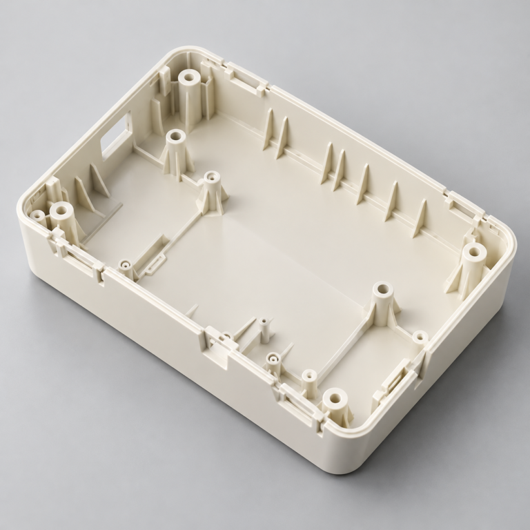
Injection Molding
Tooling and molding for your repeat plastic parts.
From prototype to production, coordinated manufacturing solutions for your custom parts.
View All Services →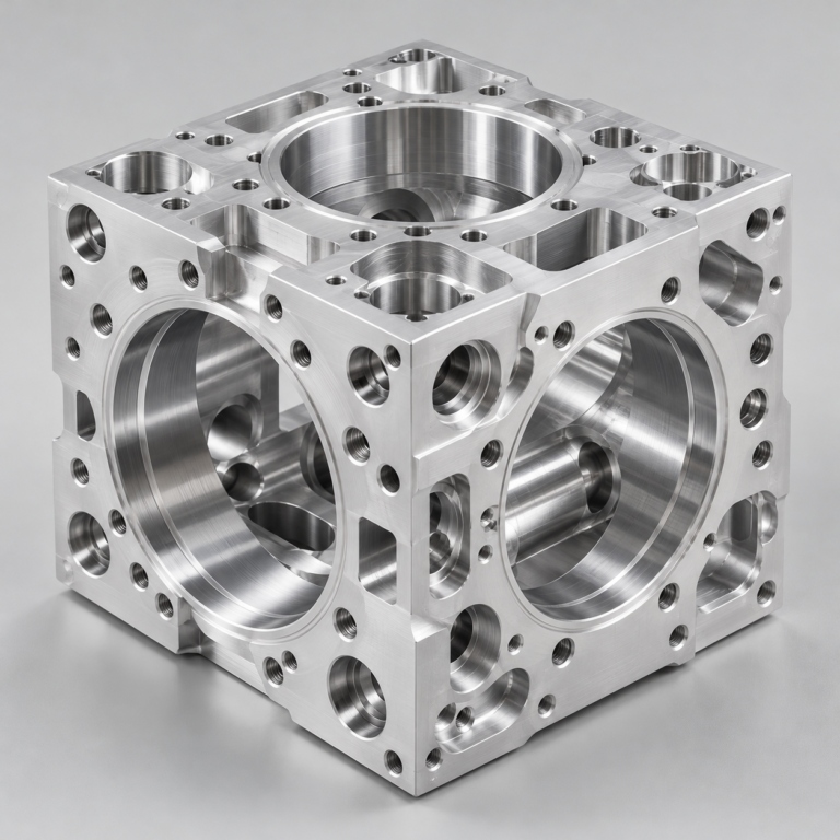
Precision parts for your tight tolerances and complex geometry.
Tooling and molding for your repeat plastic parts.
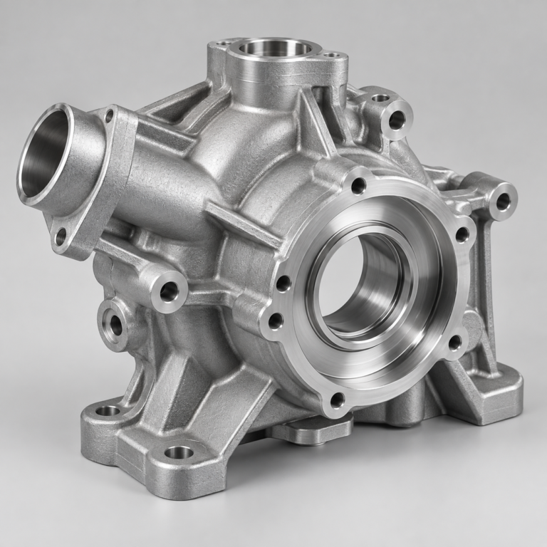
Metal casting options for your part and production volume.
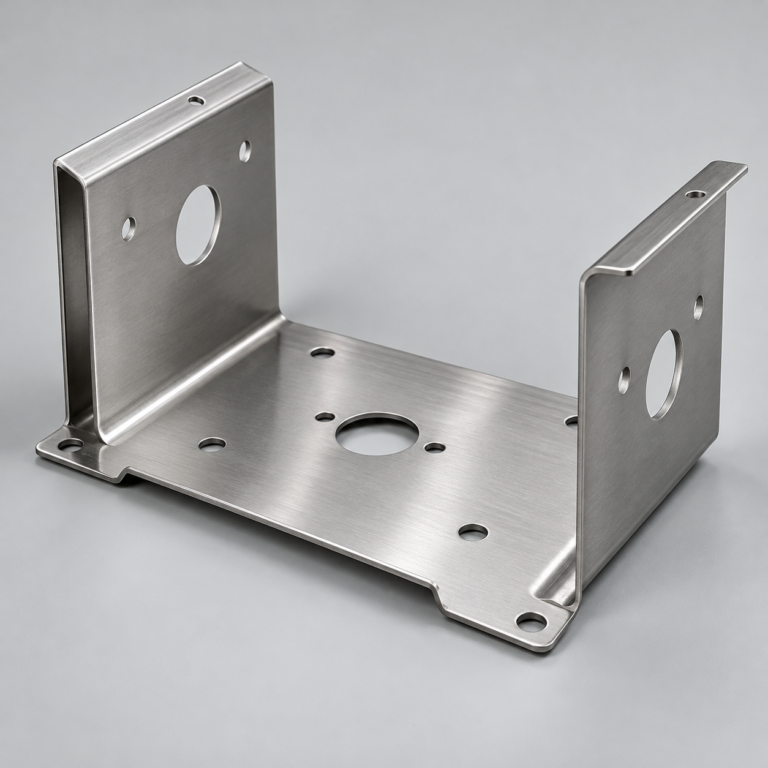
Cutting, forming and welding for your fabricated parts.
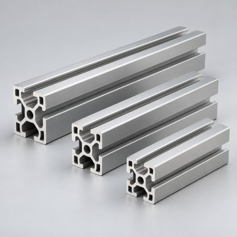
Custom profiles for your section, length and finish requirements.
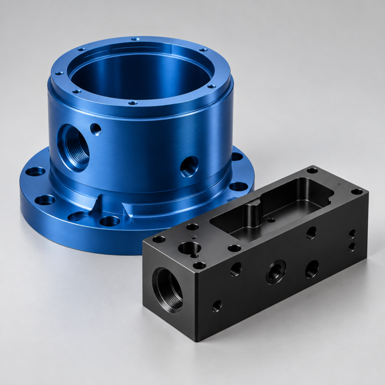
Finishes for your appearance, corrosion and wear requirements.
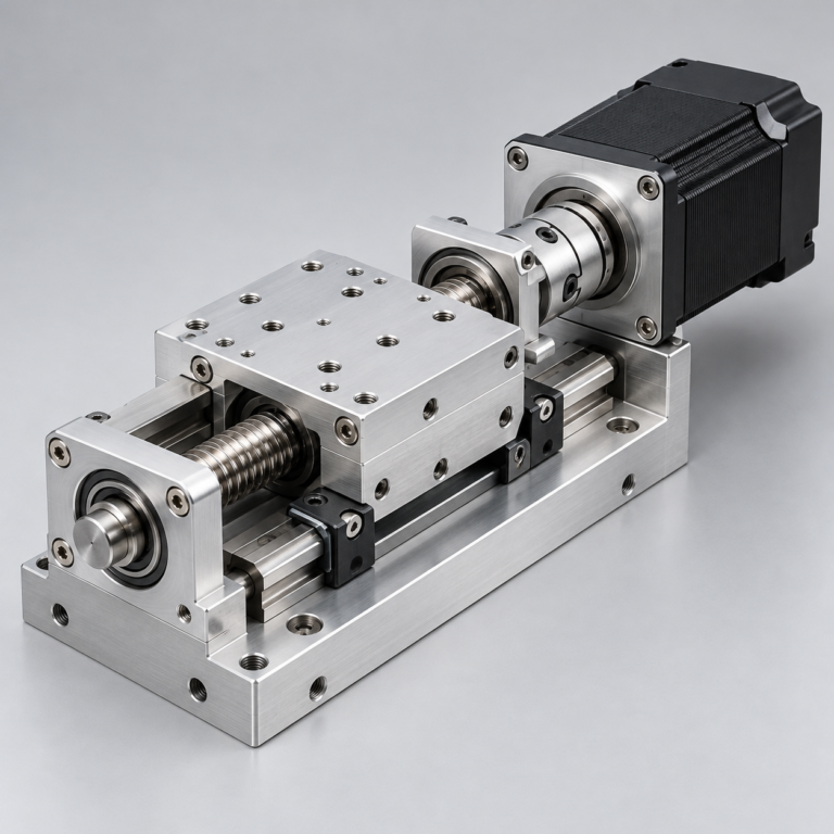
Sub-assemblies and final builds for your production program.
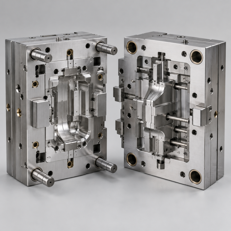
Production tooling built around your process and volume.
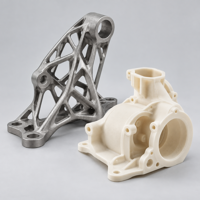
Prototype parts to check fit, function and design.
Choose air- or liquid-cooling components around your thermal and mechanical requirements.
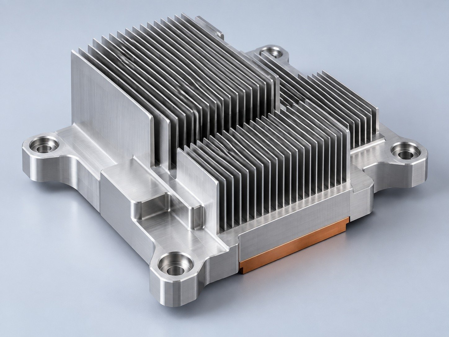
Manufacturing support for your cold plates, manifolds and cooling assemblies.
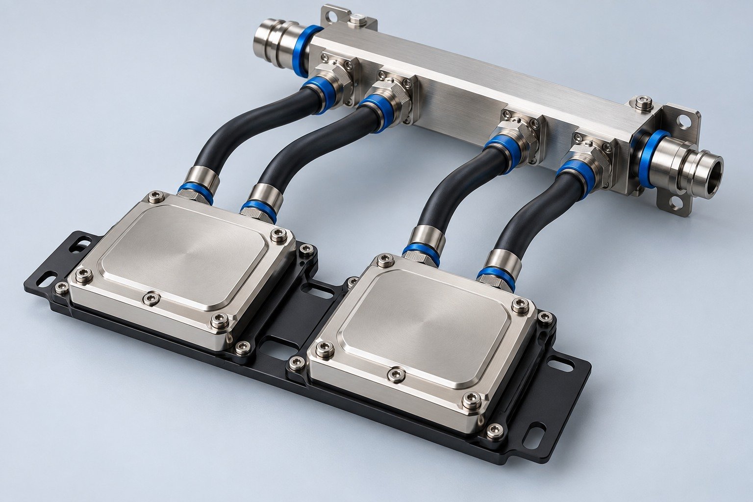
Find components for your power electronics, energy, laser and telecom application.
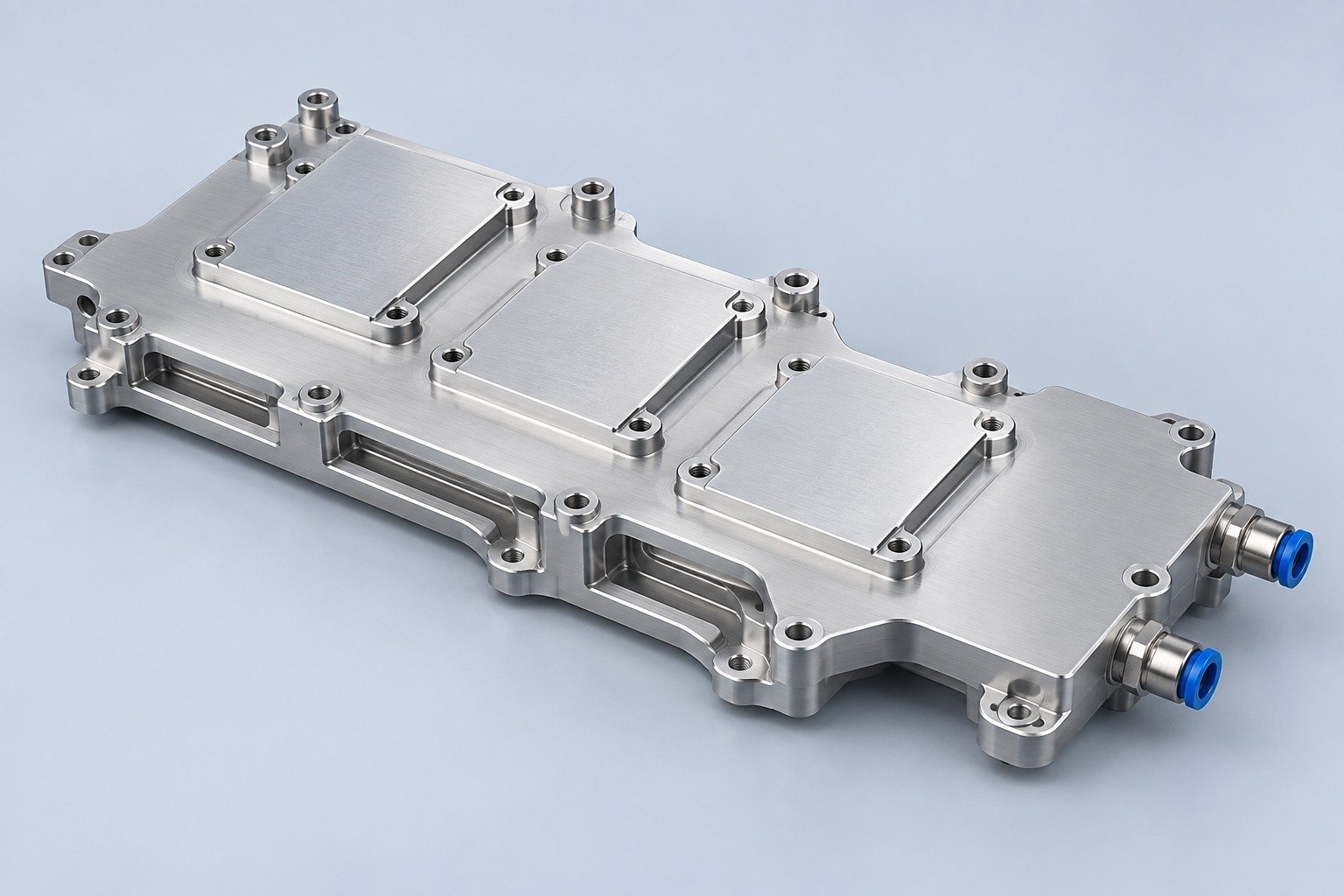
Components for your electronic systems.
Start with your functional and quality requirements.
Build around your operating environment.
From prototype to production, review material performance, manufacturability and cost for your part.
Review grade, temper and finish for your metal parts.
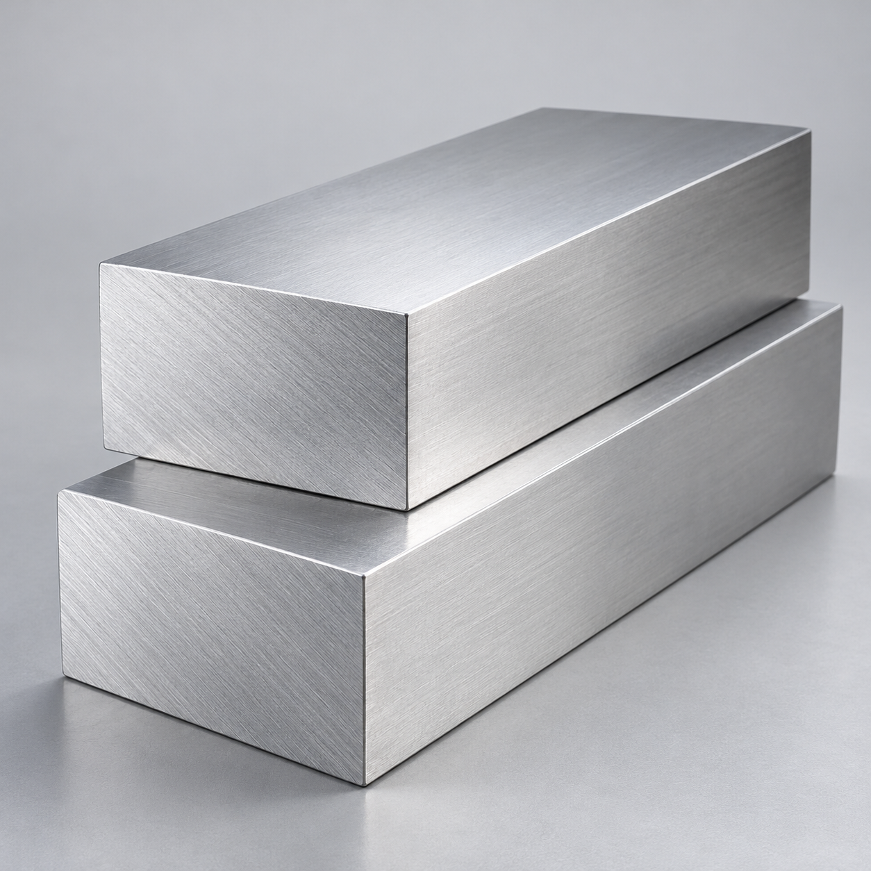 AluminumStrength, weight and machining›
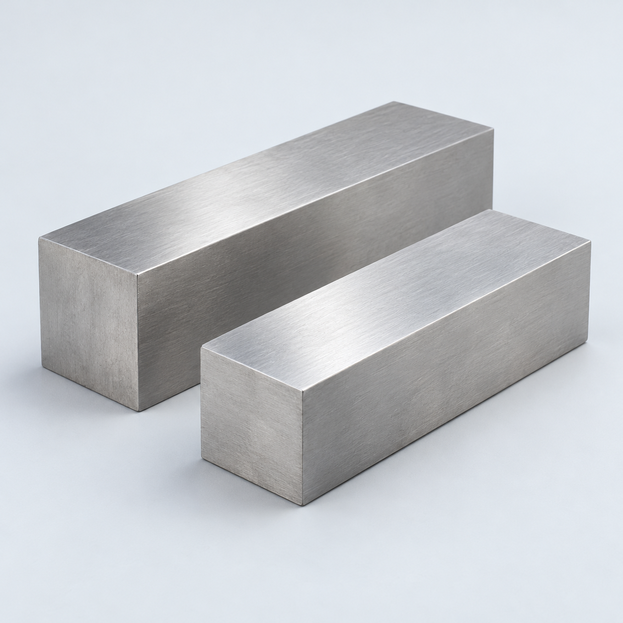 Stainless SteelCorrosion and finish requirements›
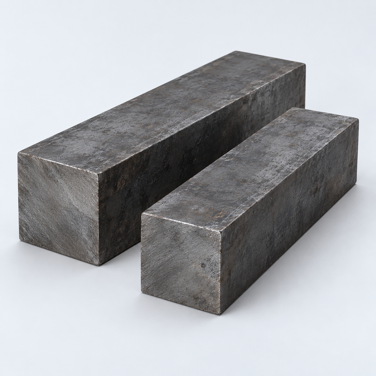 Carbon & Alloy SteelDiscuss grade and heat treatment›
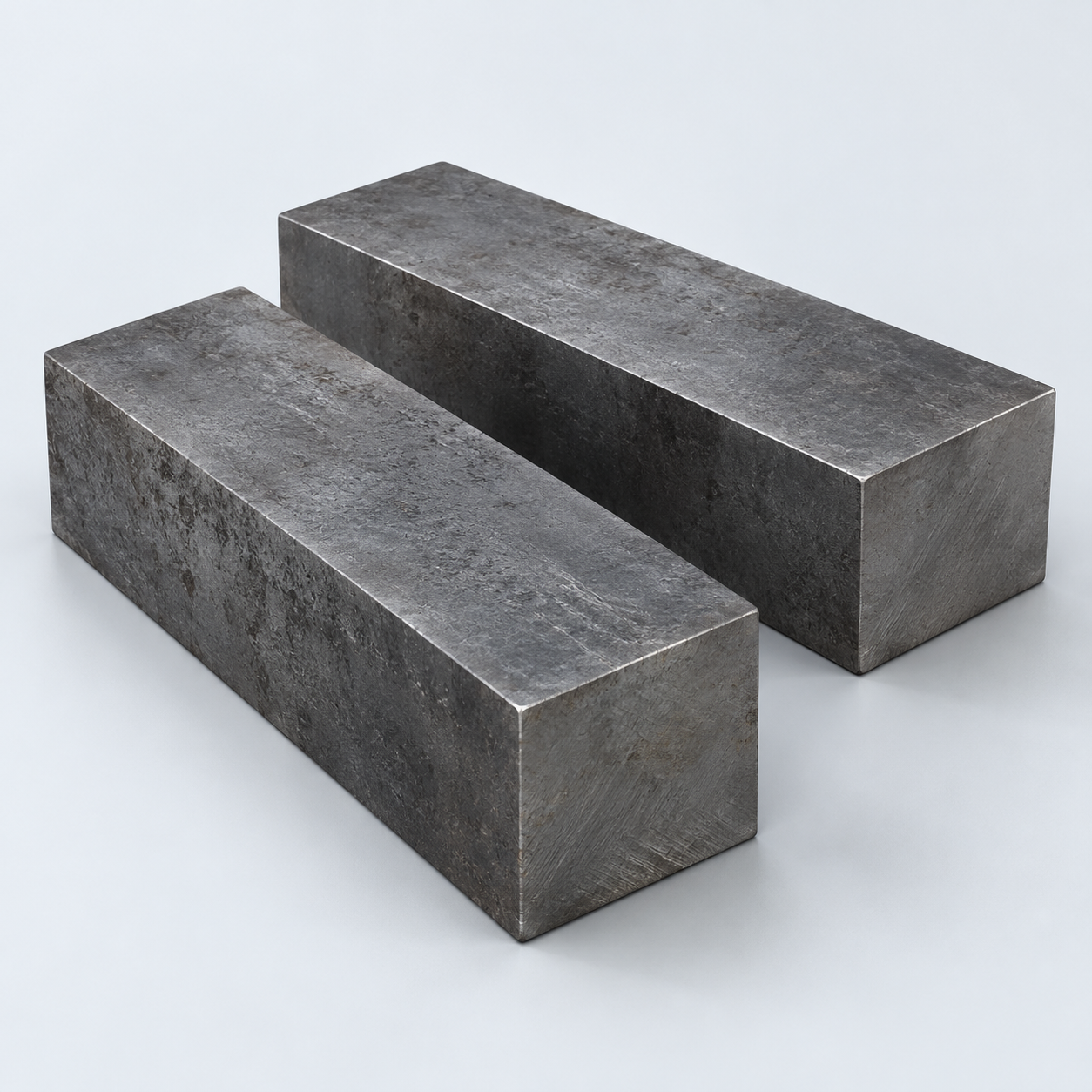 Tool SteelDiscuss tooling and wear needs›
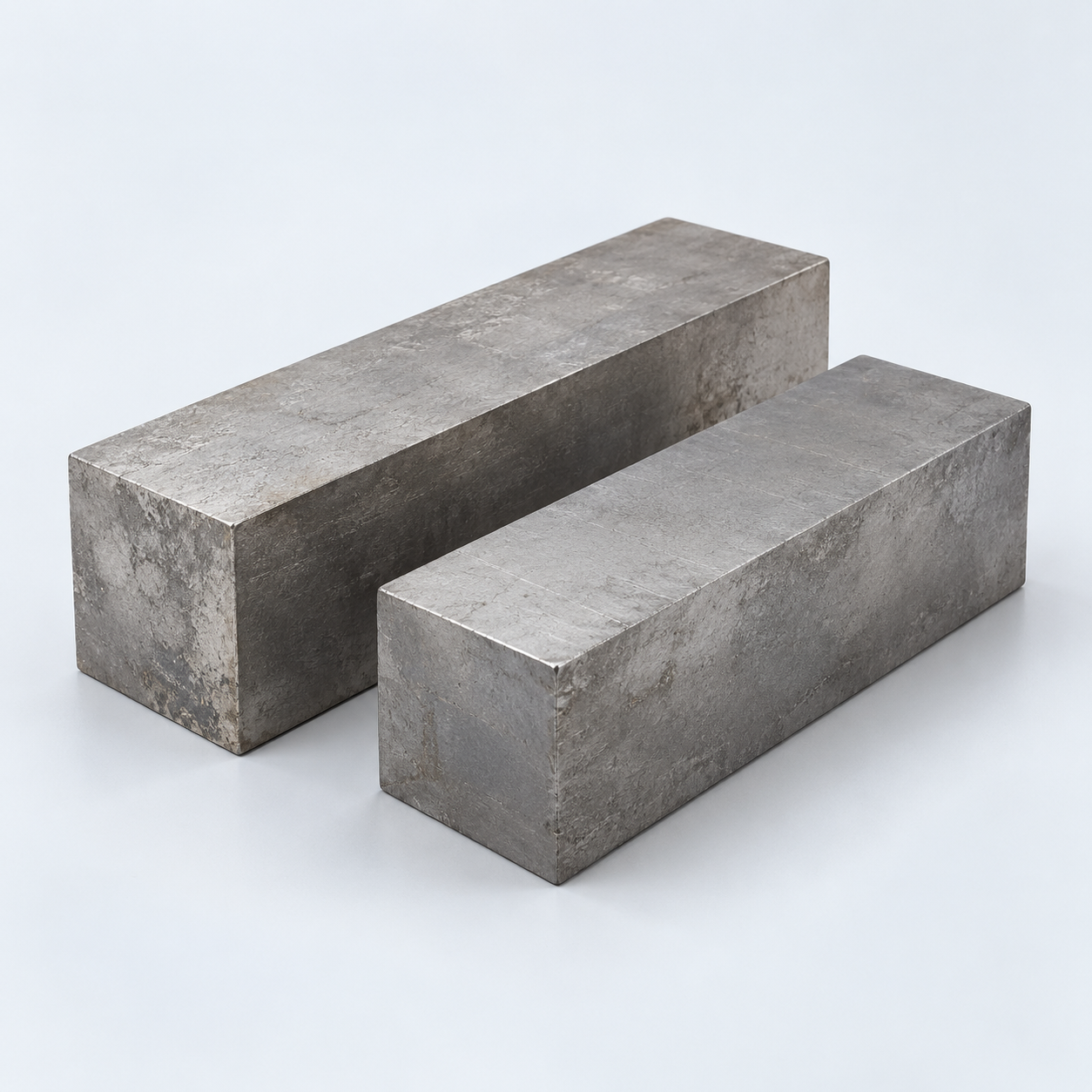 TitaniumReview grade and part geometry›
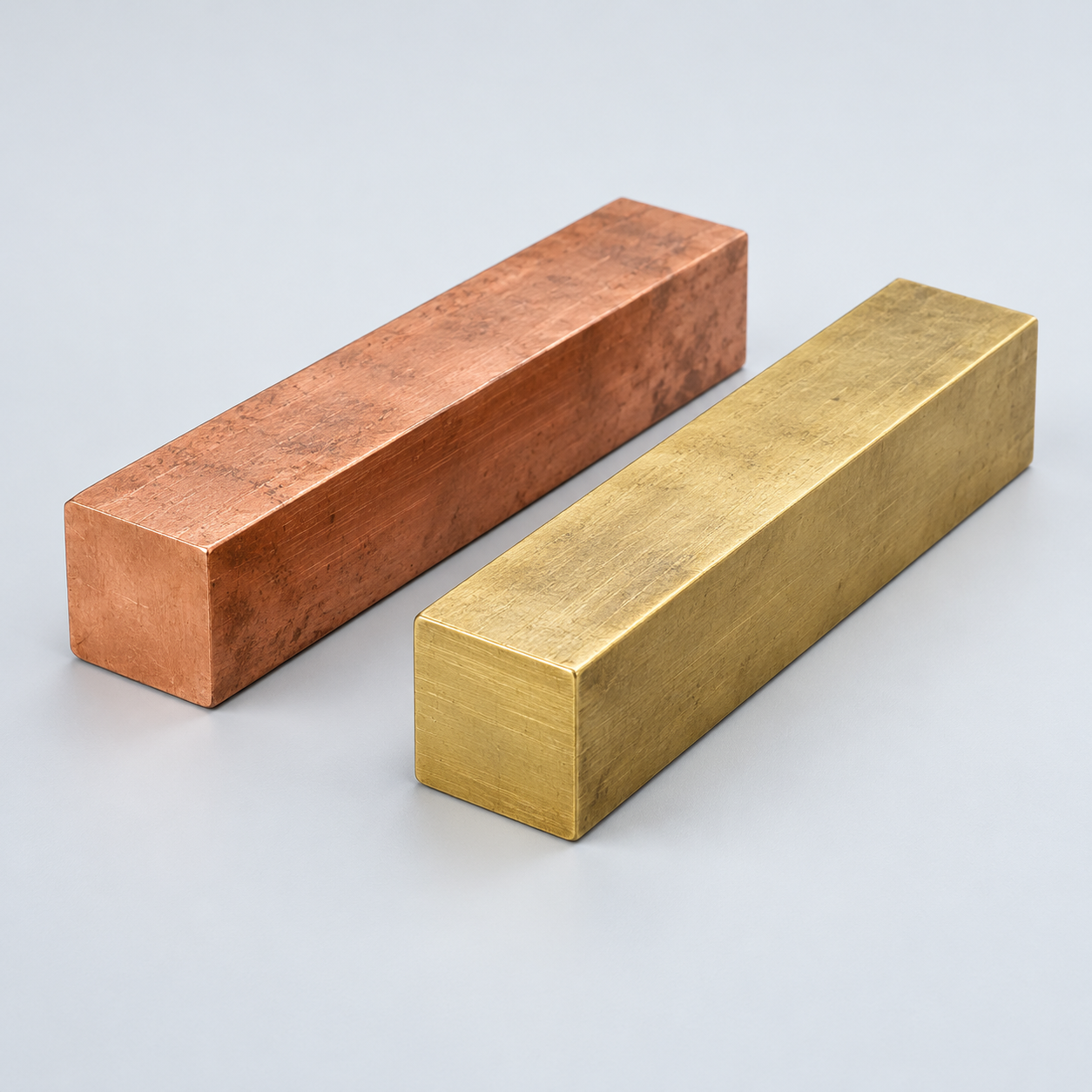 Copper & BrassDiscuss conductivity and machining›
Match your polymer to function, process and environment.
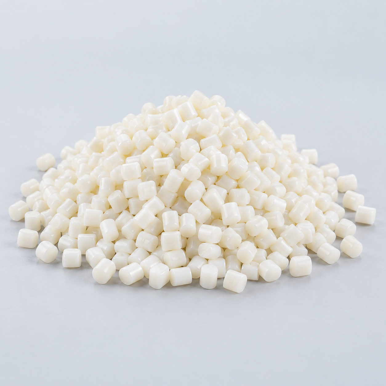 ABSReview enclosure and molding needs›
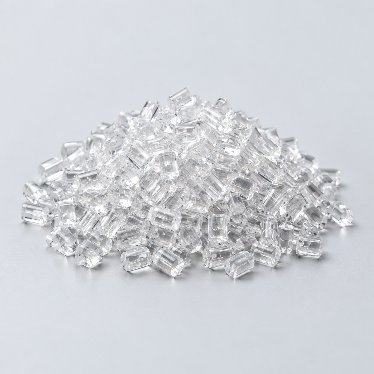 Polycarbonate (PC)Discuss clarity and impact needs›
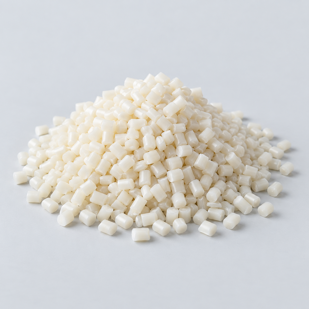 Nylon (PA)Review moisture and wear conditions›
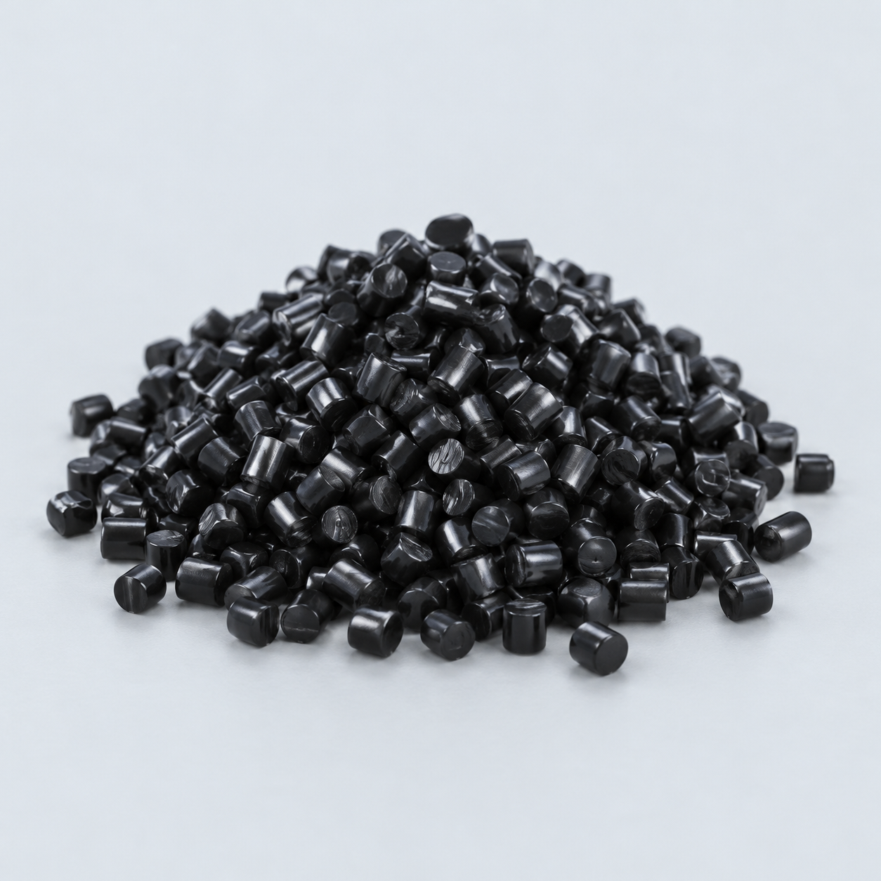 POM / AcetalReview fit and sliding features›
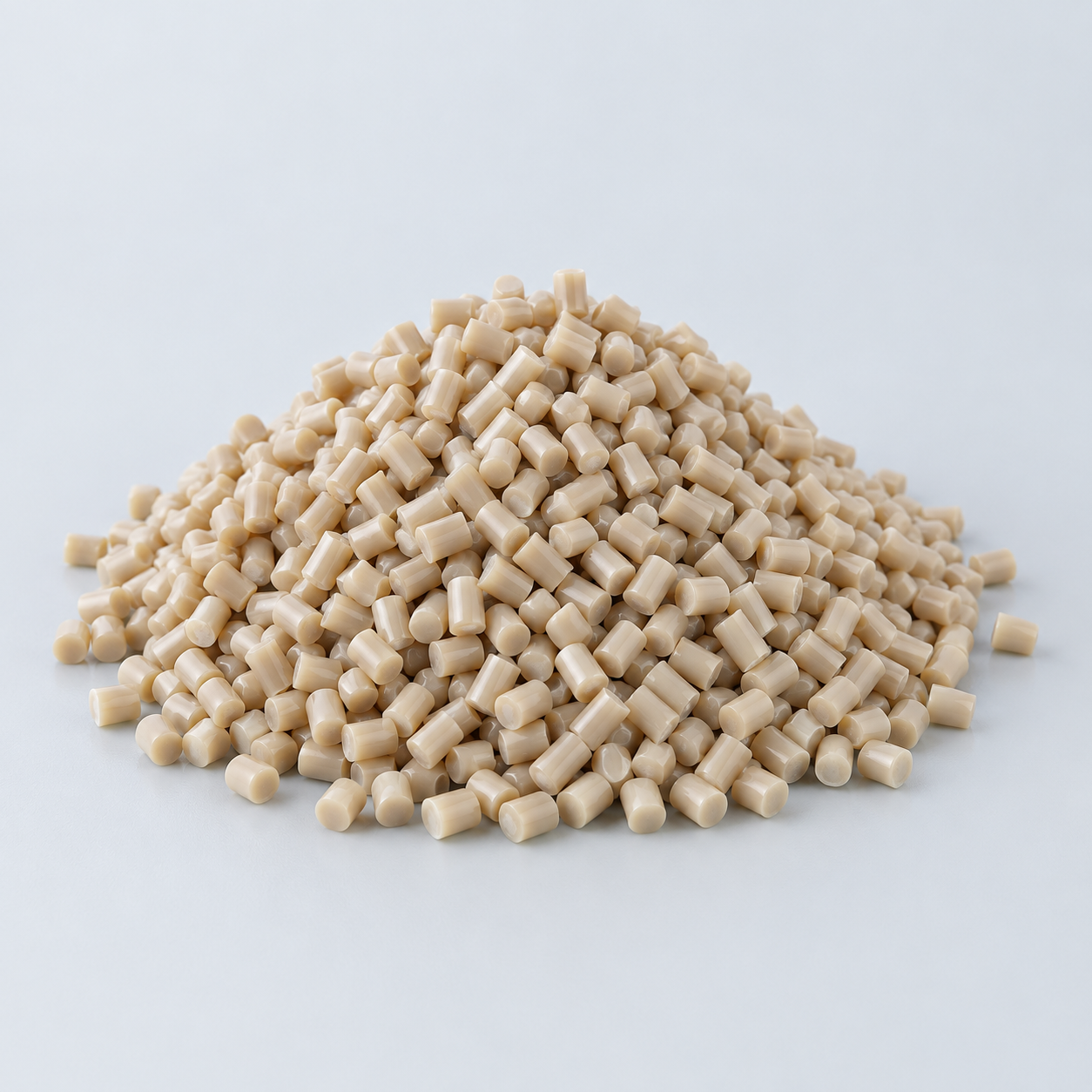 PEEKDiscuss operating conditions›
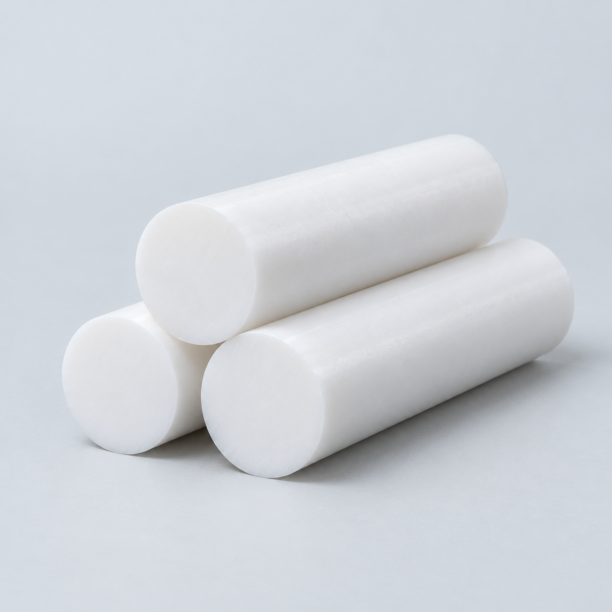 PTFEReview friction and chemical exposure›
 ULTEM / PEIDiscuss thermal and electrical needs›
Confirm grade availability and application requirements.
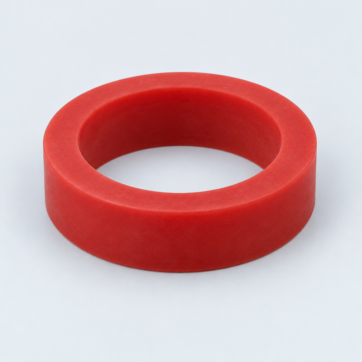 Silicone / LSRDiscuss flexible component needs›
 TPU / TPEReview flexibility and processing›
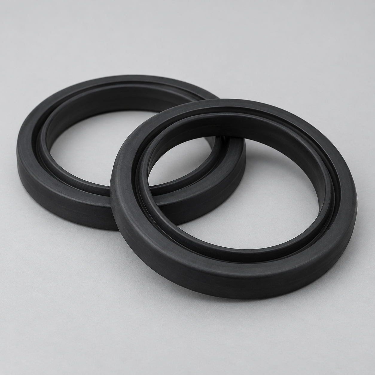 EPDMReview weathering and chemical exposure.›
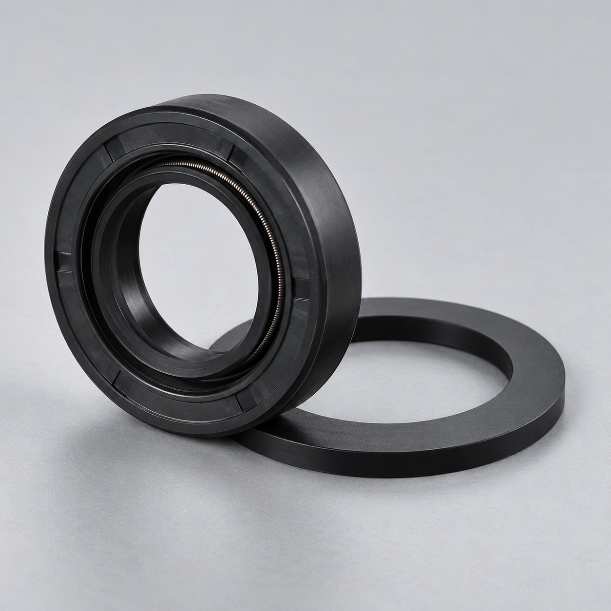 NBRReview oil and fuel exposure.›
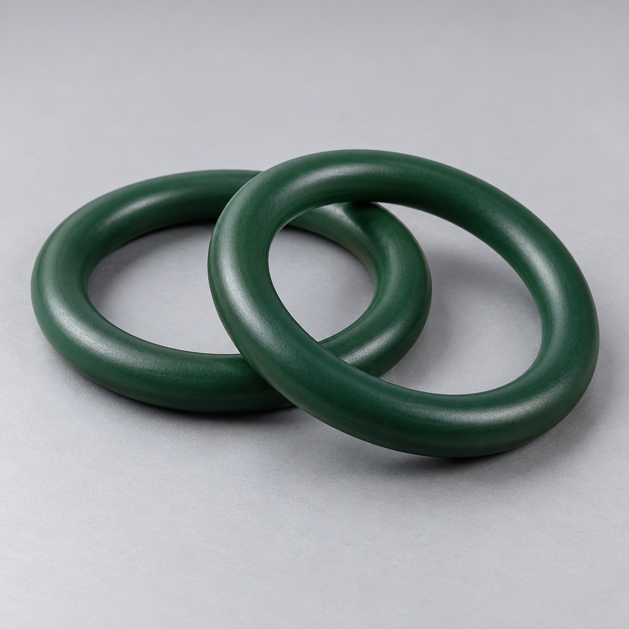 FKMReview temperature and chemical exposure.›
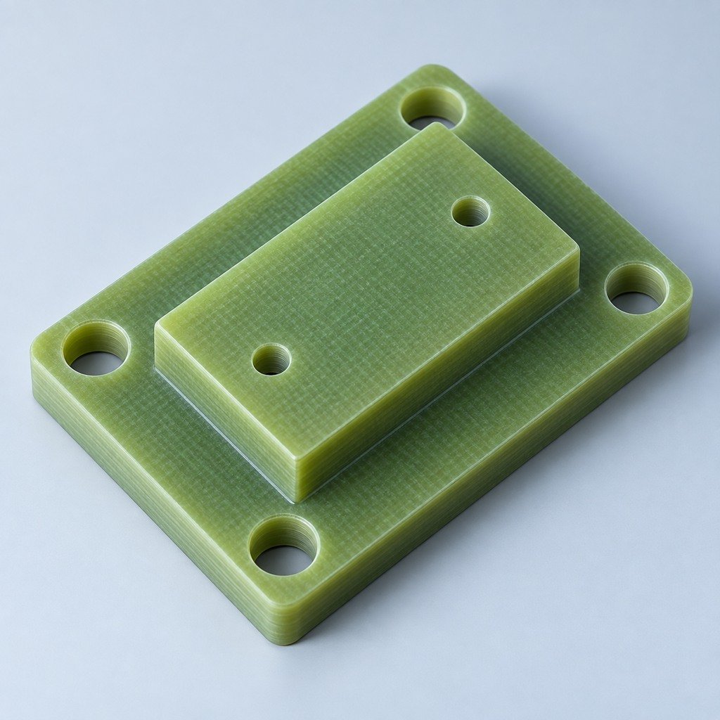 G10 / FR4Review insulation and laminate needs›
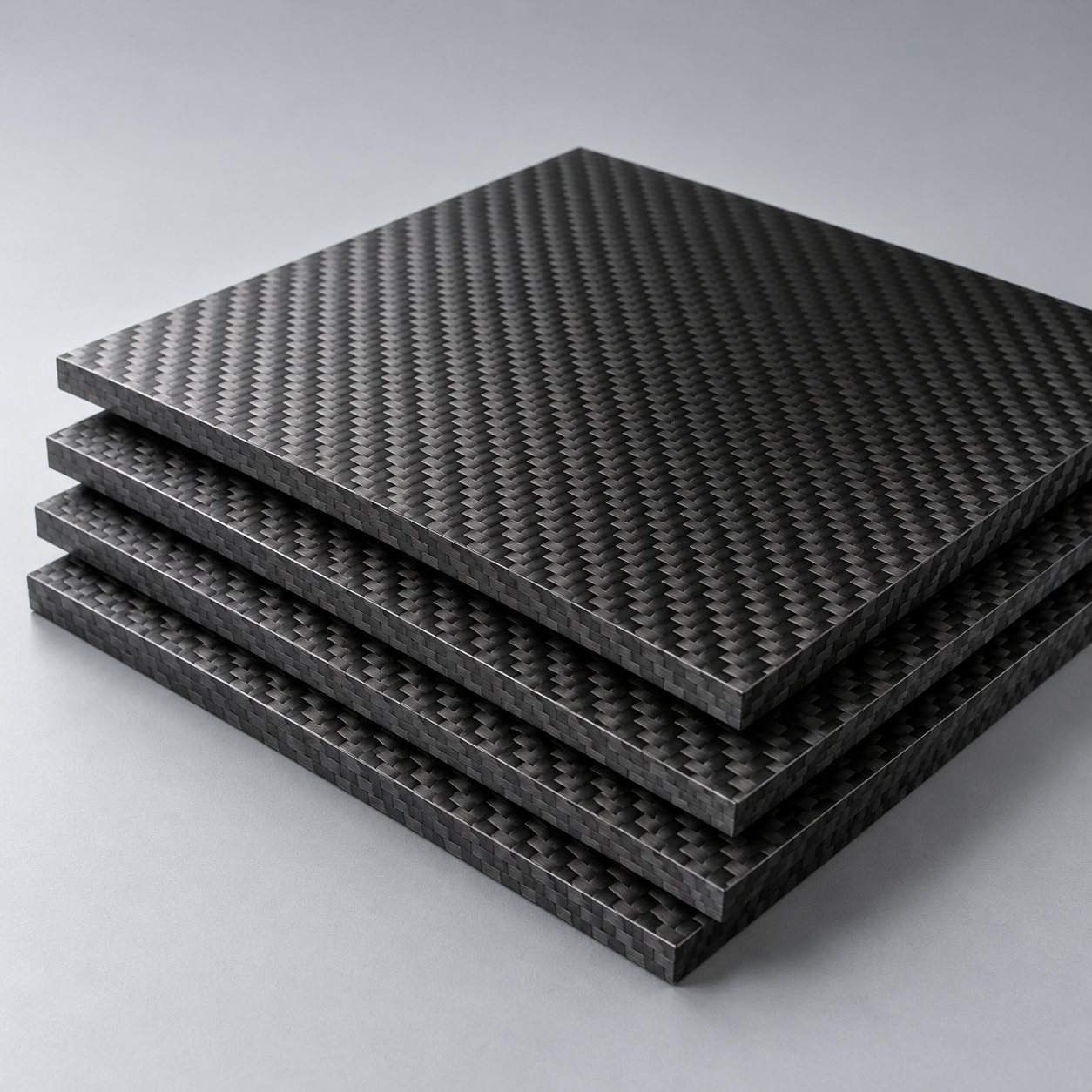 CompositesReview stiffness, weight and laminate.›Customer-Specified MaterialsConfirm your grade and requirements.›Other Specialty MaterialsDiscuss your application and grade.›
Practical guidance for your part geometry and material decisions.
Prepare your process, budget and sourcing questions.
Build your knowledge before production.
Learn who we are and how we operate.
Find our U.S. support team or start a conversation.
SINGLE-STATION STAMPING DIES
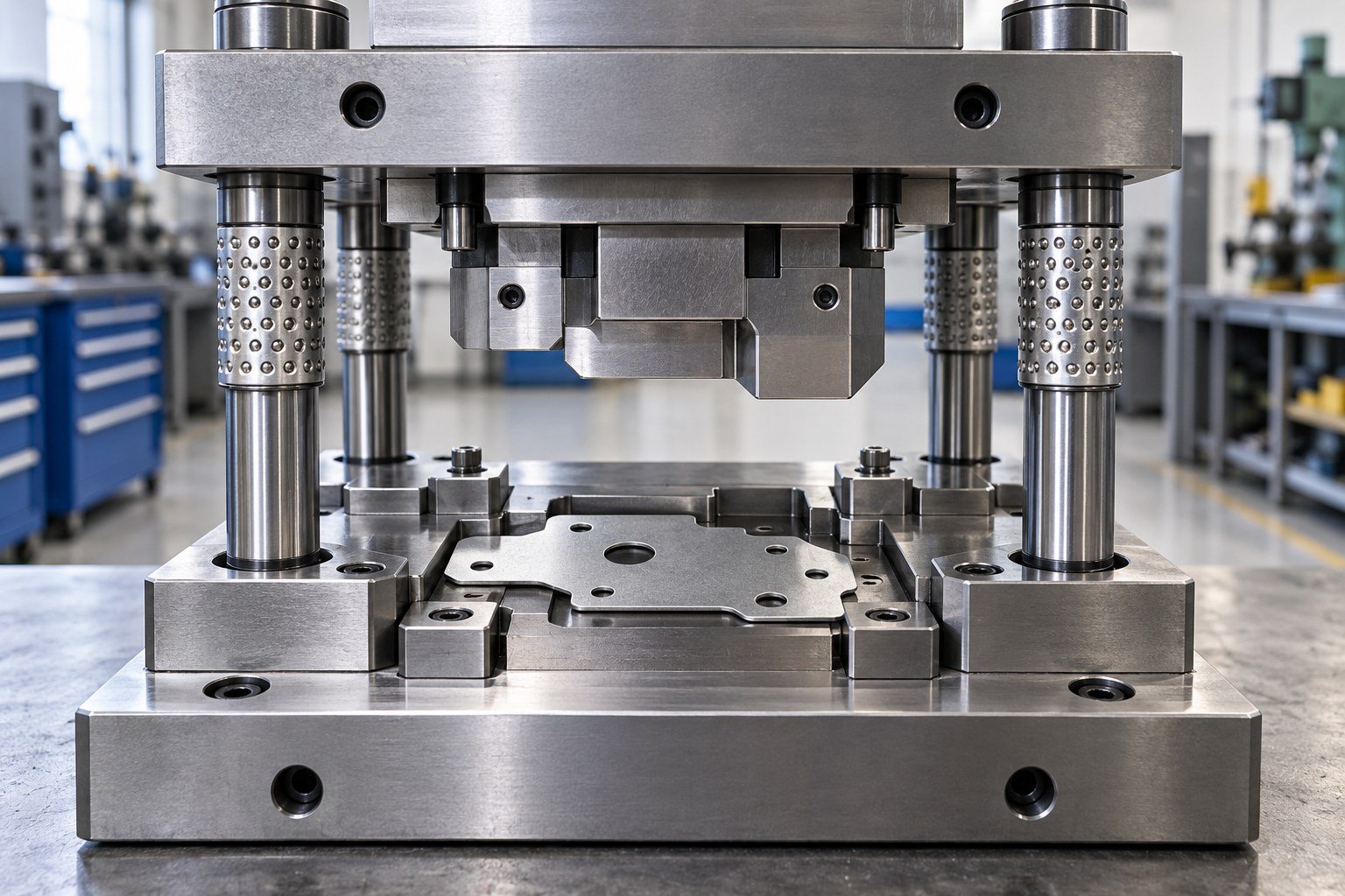
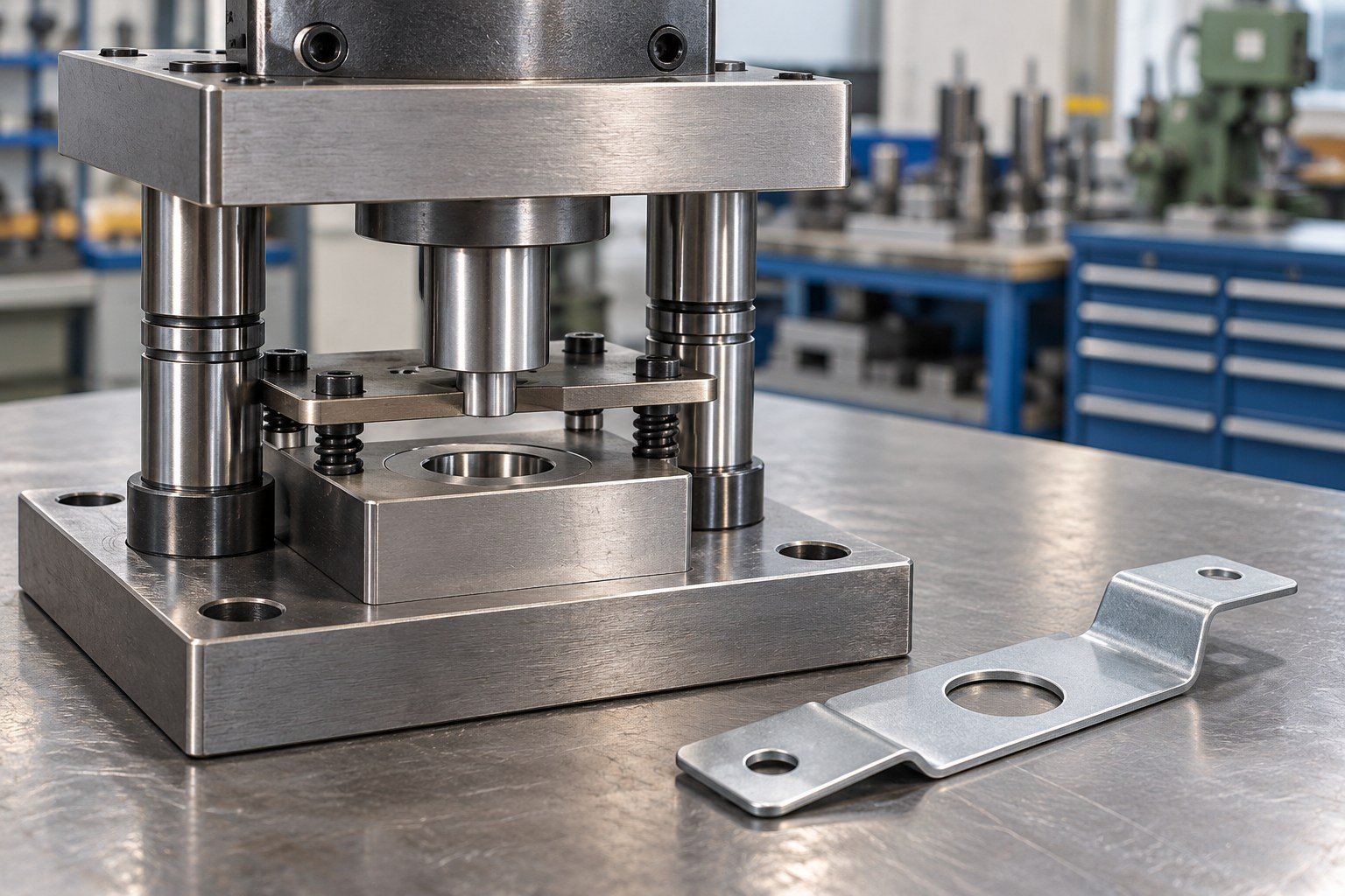
Plan your single station stamping dies around the actual sheet grade, thickness, part drawing and receiving press. Define the operation, location method and tryout acceptance before tooling manufacture.
1 station. A defined operation and acceptance plan.
Review Your Stamping Tool →6 quote inputs ↓Drawing approved · Tryout reviewed · Handover defined
FOR YOUR STAMPING PROGRAM
Compare the complete operation plan. Tool purchase and stamped-part production are separate scopes.
ON THIS PAGE
For your discrete operation, staged route or secondary feature.
Review single-station tooling →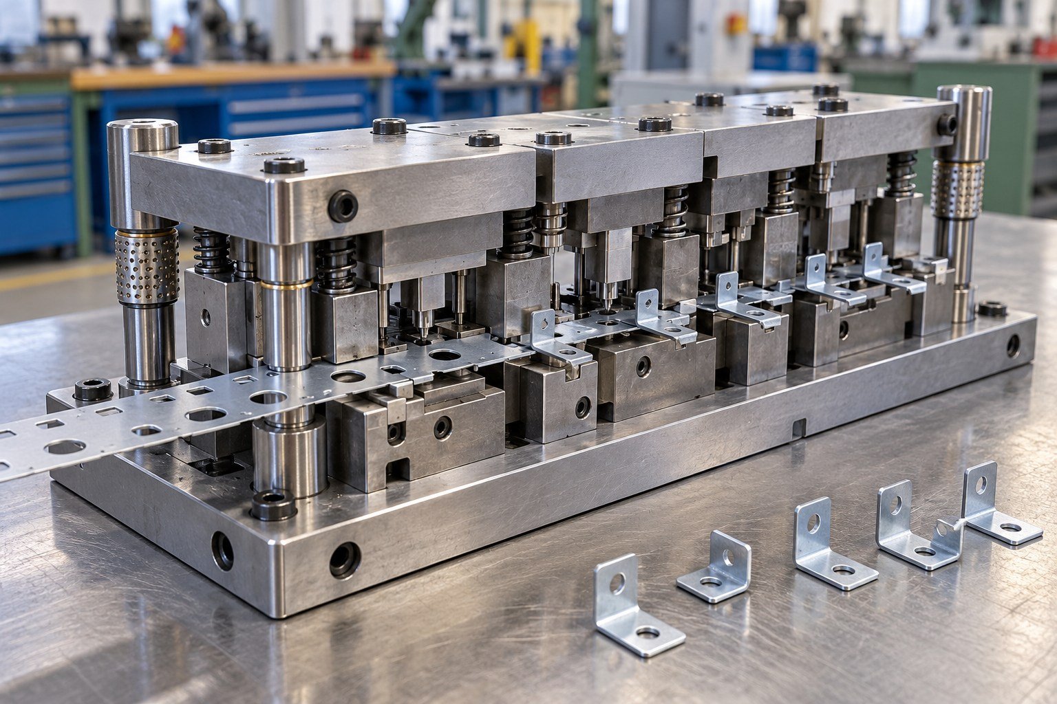
COMPARE THE OTHER ROUTE
For your connected-strip sequence, pilots and repeated supply.
Review progressive tooling →FOR YOUR STAMPING PROGRAM
Resolve these inputs early so the quote addresses the part and equipment you will actually use.
Grade, condition, thickness and grain direction.
Blanking, piercing, bending, forming or drawing.
Mounting, shut height, stroke and available capacity.
Datums, burr direction, geometry and fit.
Drawings, wear parts, care and release conditions.
FOR YOUR STAMPING PROGRAM
A tool price is useful only when the operation, trial and delivery scope match.
Align the part model, drawing and tool concept before manufacture.
Confirm the press, handling and relevant feed interfaces.
Identify datums, sample quantity, burr, geometry and fit checks.
Separate tooling, trial stock, corrections, spares, production and freight.
FOR YOUR STAMPING PROGRAM
Specify the operation and deliverables, then compare suppliers on the same basis.
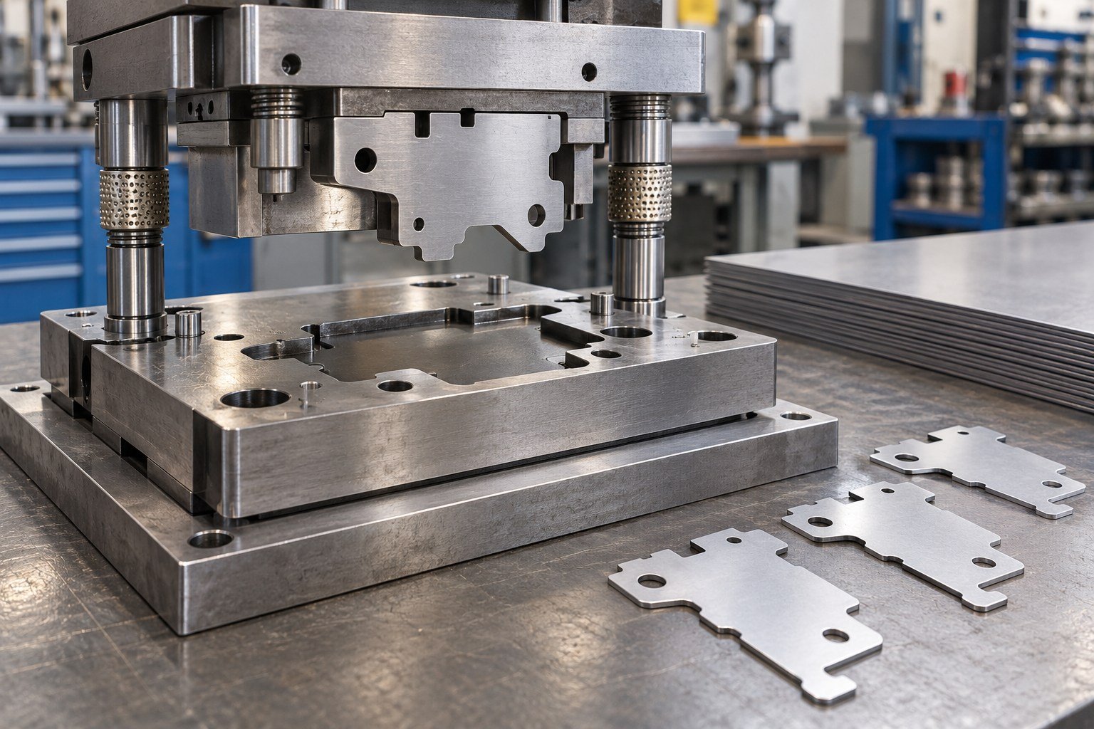
Define the outside profile and the cut edge your part must accept.
Review this tooling scope ↓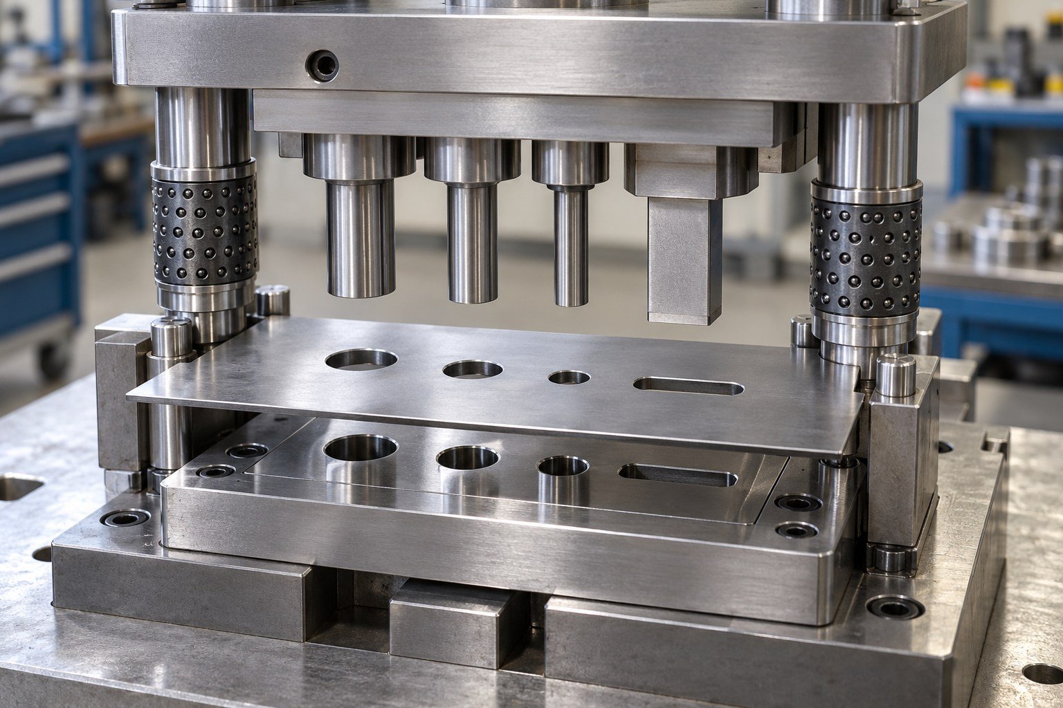
Locate holes and slots from the datums used in your next assembly.
Review this tooling scope ↓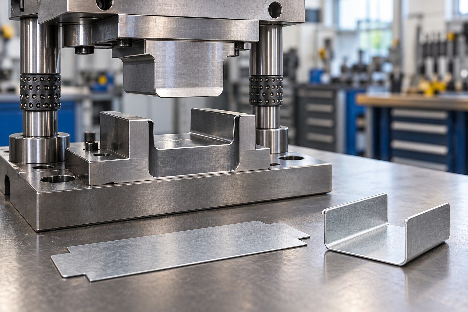
Review bend sequence, support and springback around the finished shape.
Review this tooling scope ↓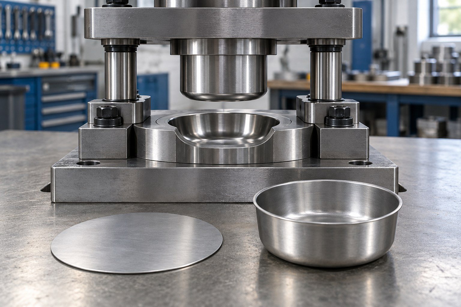
Review material flow, blank holding and draw geometry for your actual stock.
Review this tooling scope ↓FOR YOUR STAMPING PROGRAM
Design, manufacture, tryout, corrections and delivery are separate schedule items.
Share the controlled part, stock specification, quantities and receiving-equipment data.
Resolve location, work sequence, stripping, removal and machine interfaces before cutting the tool.
Define material, treatment, machining, purchased components and assembly checks. Approve substitutions.
Use the agreed stock and equipment basis. Identify samples and record relevant trial observations.
Assign cause review, correction scope, cost responsibility and the next sample requirement.
Confirm the tool revision, records, spares, preservation, ownership and receiving requirements.
FOR YOUR STAMPING PROGRAM
Stock names, tool-steel names and press capacity are different inputs; record each clearly.
Use the actual alloy, temper or condition.
State nominal thickness and the agreed variation.
Identify grain direction and protected faces.
Confirm discrete blanks or coil and strip requirements.
D2 stamping die steel or A2 stamping die steel are candidates for review, not universal selections.
Define heat treatment and verification as quoted.
Identify replaceable punches, dies, pilots or inserts.
Agree material identification and available evidence.
Die footprint, fastening and access.
Shut height, stroke and opening requirements.
Evaluate the operation and press characteristics.
Part, slug, scrap and handling interfaces.
Define visible faces and permitted tool witness marks.
Agree the trial and production basis.
Define service and adjustment allowances.
Identify preservation and maintenance responsibility.
FOR YOUR STAMPING PROGRAM
Agree the relevant input, design decision and check for each operation.
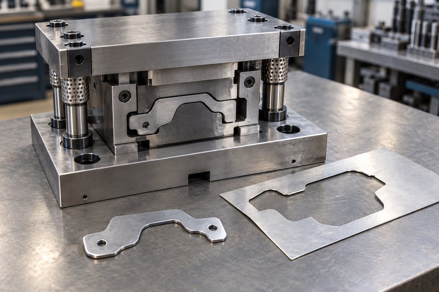
A simple blanking die cuts an outside profile. Review the blank location, stock support and scrap path.
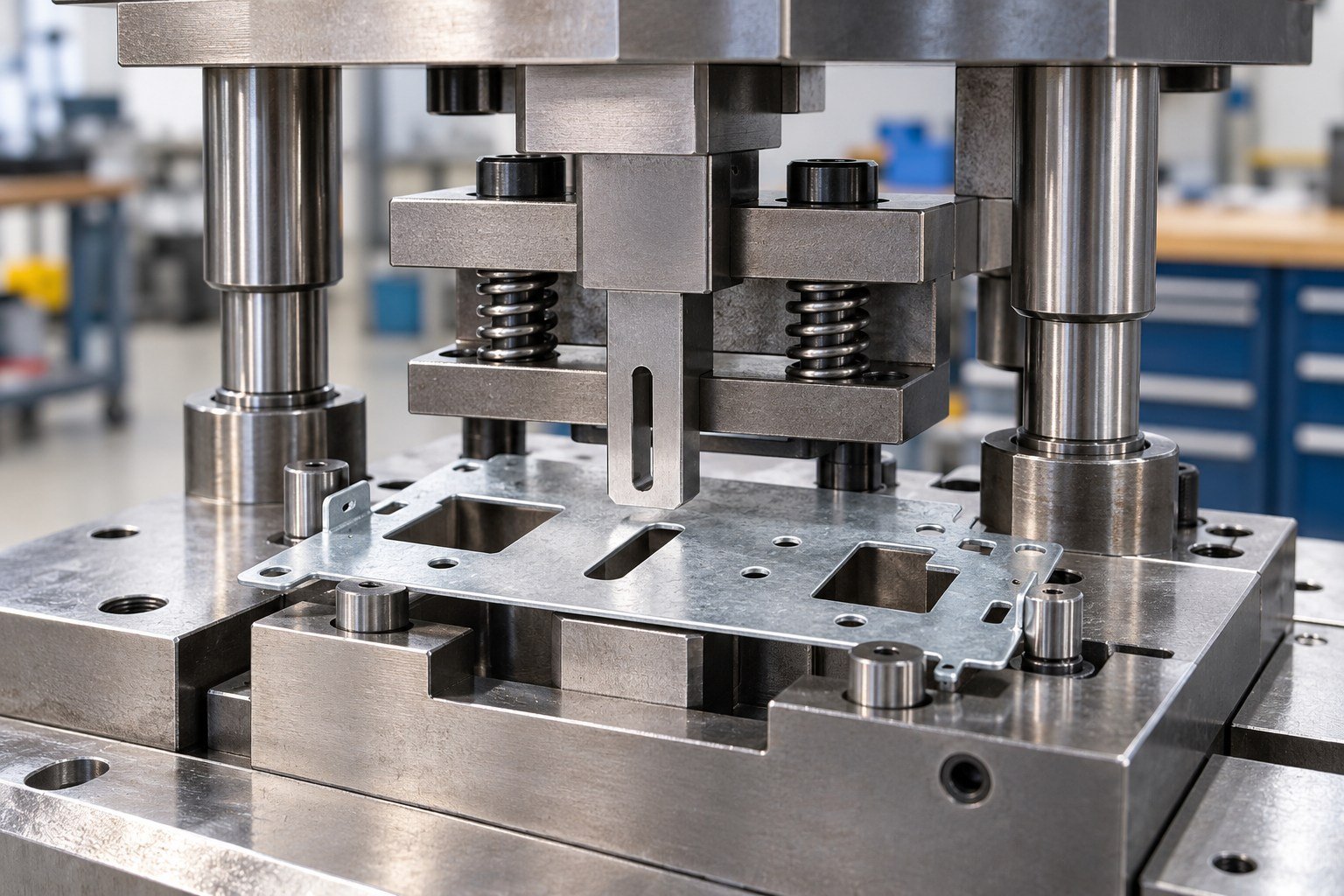
Connect punch locations to the finished-part datums. Do not let an uncontrolled blank edge become the only reference.
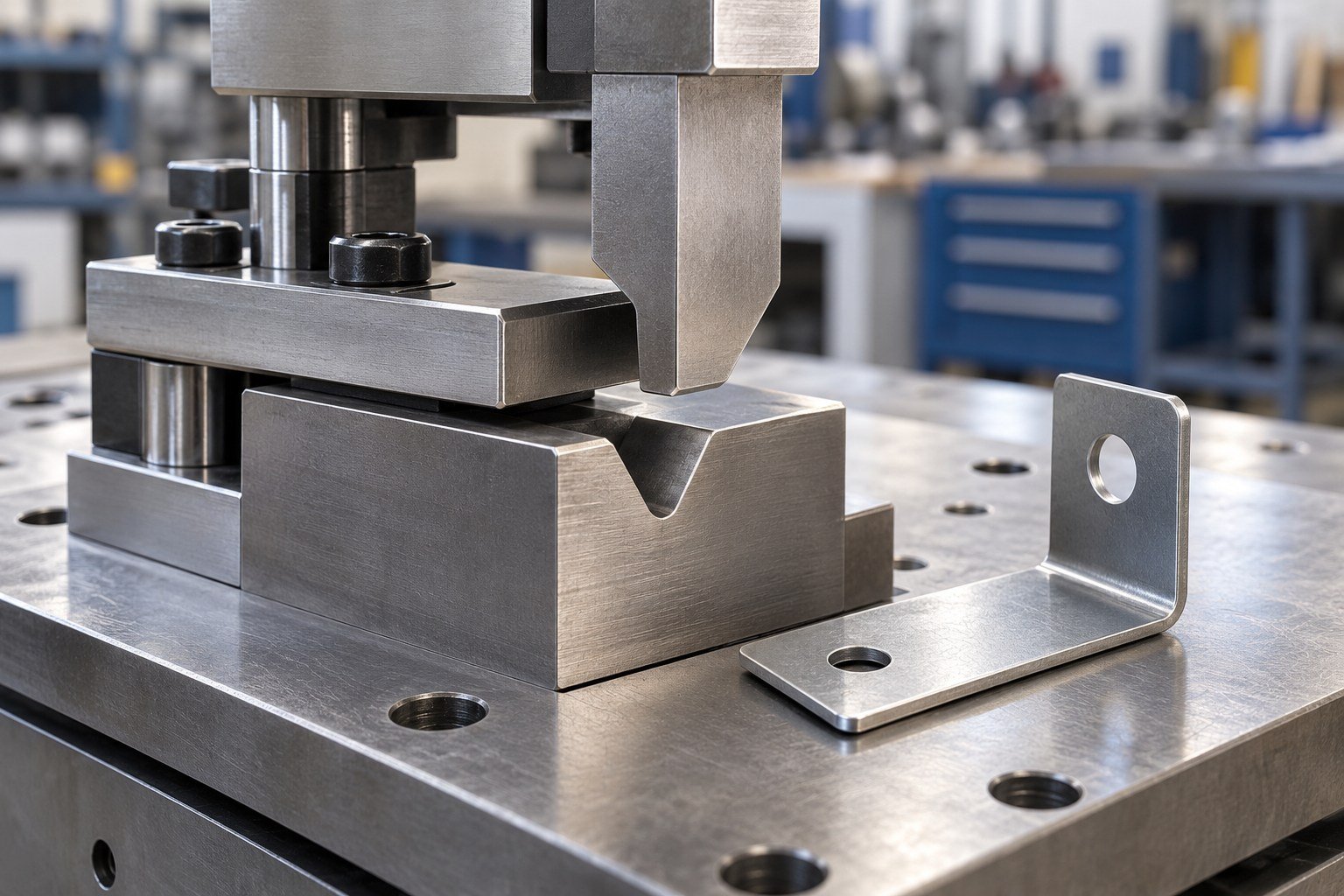
Agree what the tool must produce after the part is released, rather than accepting an angle only while it is loaded.
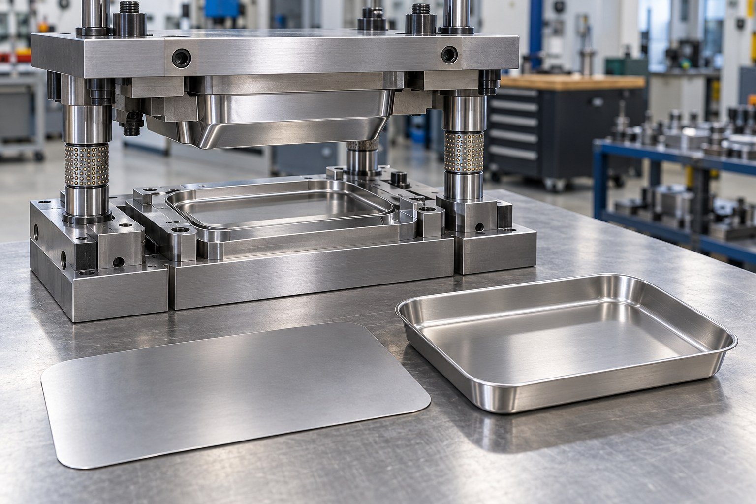
Review the blank, radii and holding concept together. Formability and surface requirements are project-specific.
FOR YOUR STAMPING PROGRAM
The blank, the work-in-process part and the finished drawing need a consistent location and inspection plan.
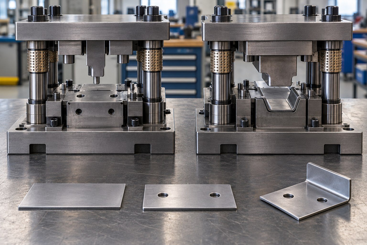
Record these decisions on controlled documents so later operations use the same basis.
FOR YOUR STAMPING PROGRAM
Resolve the features that control cutting, location, forming and repeat use; avoid one-size-fits-all promises.
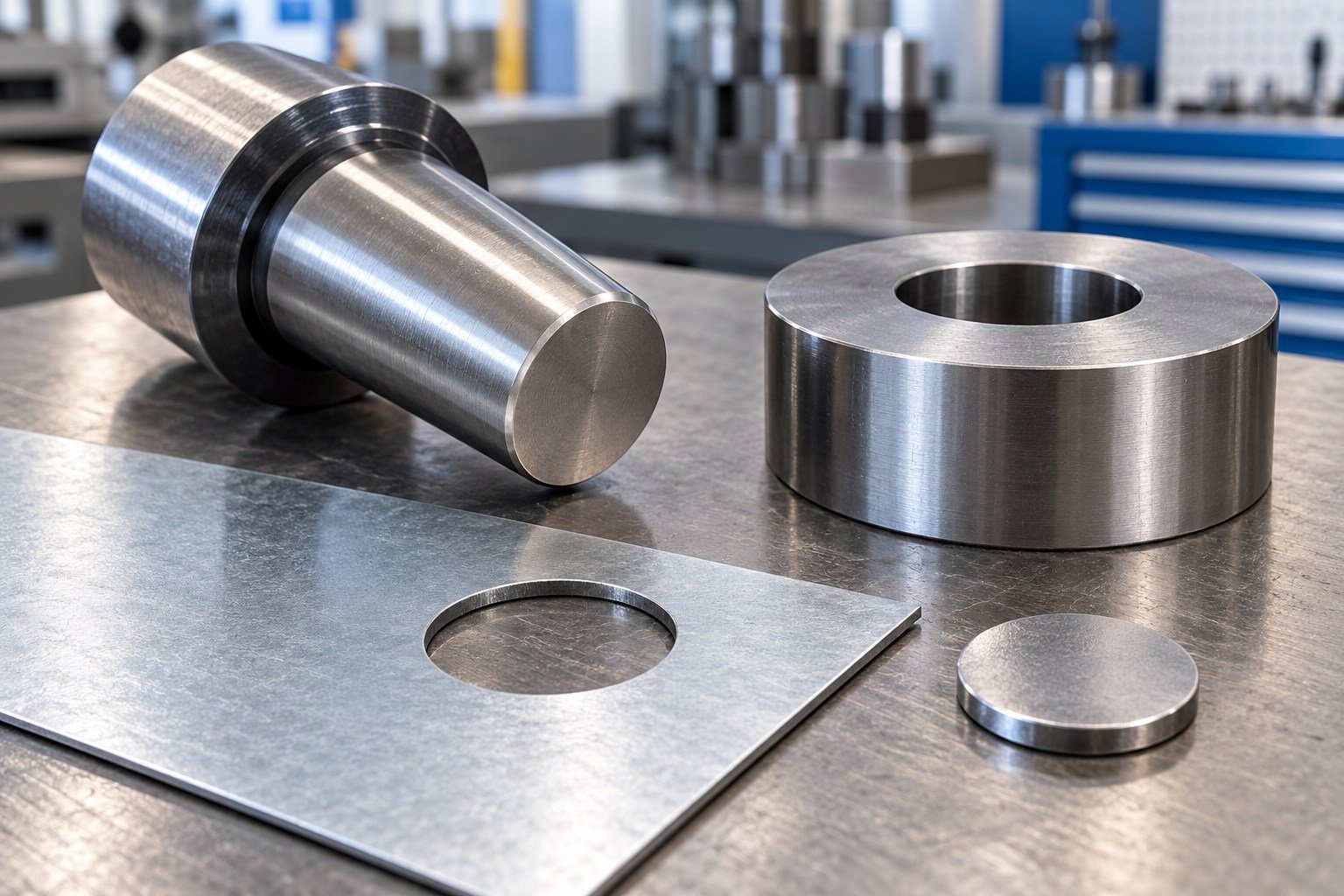
Stamping die clearance depends on material, thickness, punch geometry and the required cut edge. A universal percentage does not define your tool.
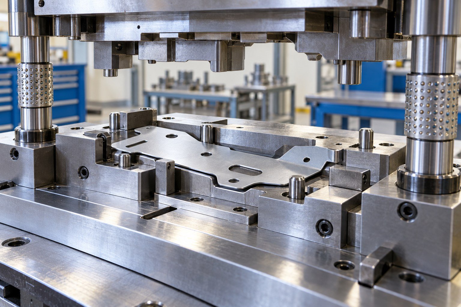
Single station die design must resolve how the blank is supported, located, stripped and removed.
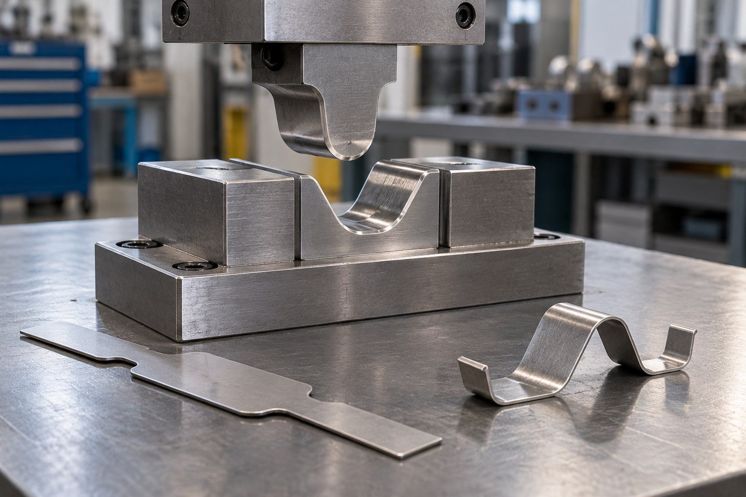
For a single station forming die, connect material variation and bend sequence to the finished geometry.
FOR YOUR STAMPING PROGRAM
Define condition, compatibility and reapproval before committing to work.
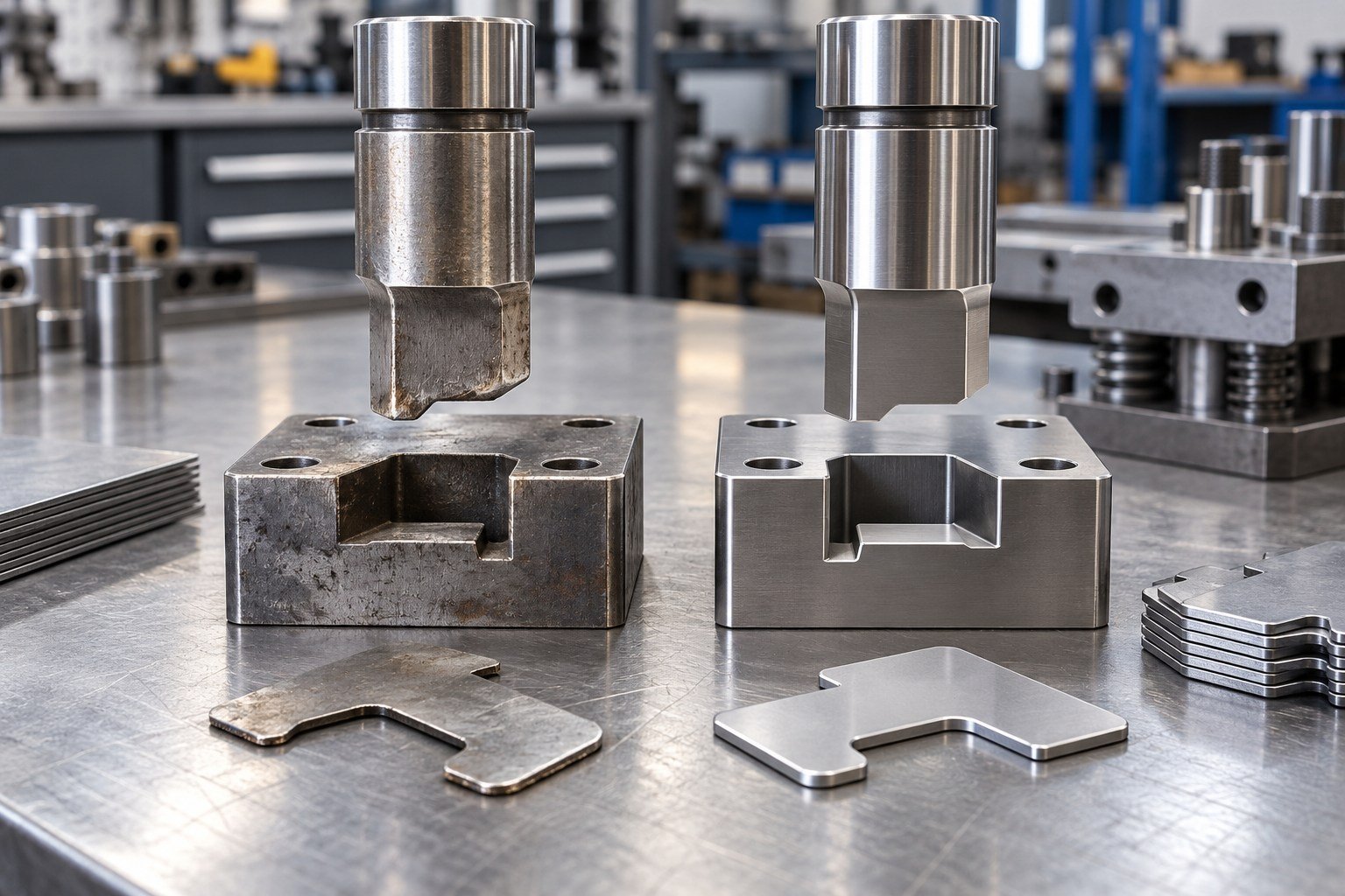
Start with the defect, tool condition and part evidence. Authorize the proposed work before grinding or replacing functional surfaces.
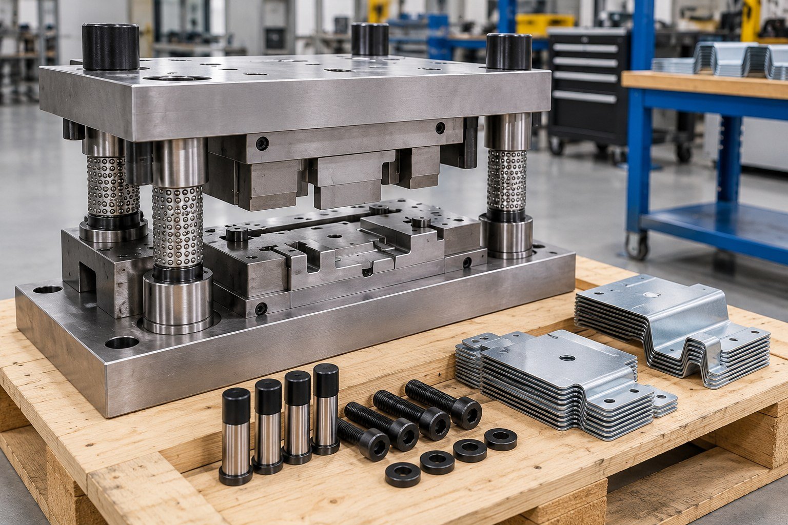
A usable tool needs compatible press interfaces and a defined receiving trial, not just a shipping arrangement.
FOR YOUR STAMPING PROGRAM
Verify the working tool and the produced part as related but separate evidence.
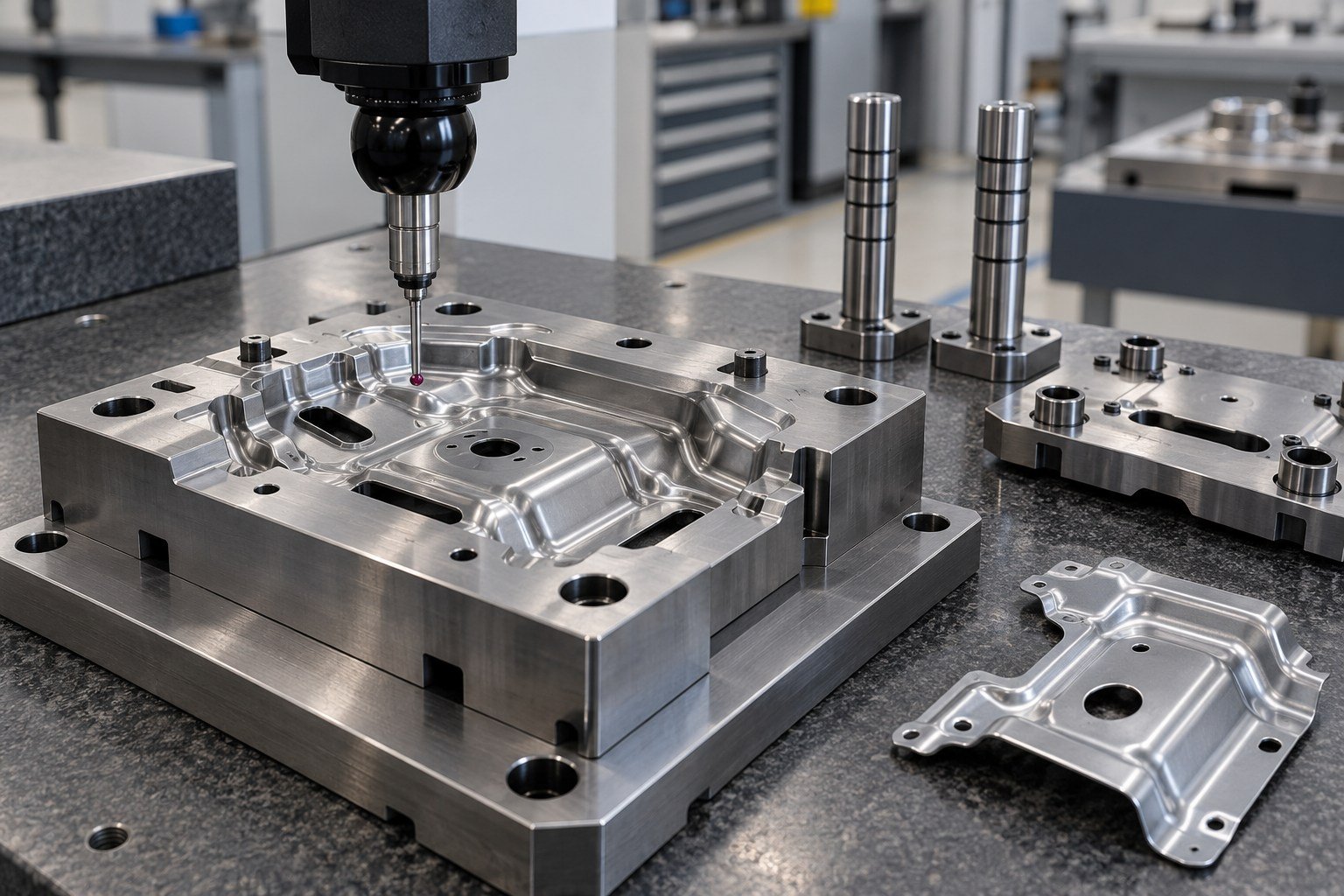
Check agreed punch, die, locator and press-interface features against the approved tool design.
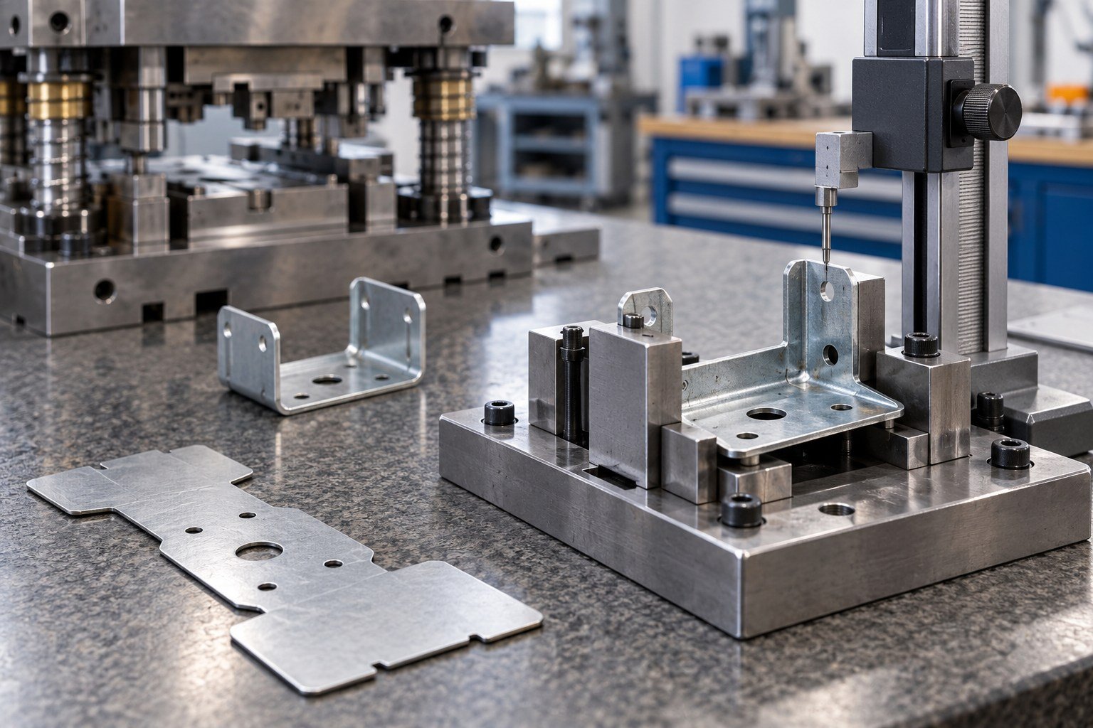
Single station die tryout should connect part results to the stock, setup and drawing revision.
FOR YOUR STAMPING PROGRAM
Agree availability, scope and responsibilities. Images illustrate tooling concepts, not customer reports.
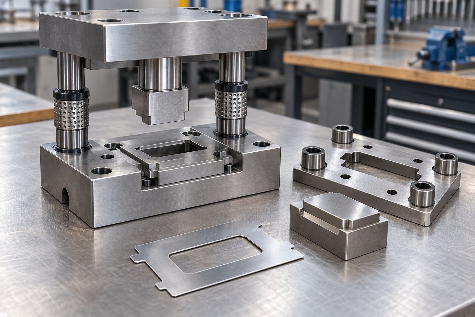
Approve the tool concept before manufacture.
Planning checklist only; not an issued customer or inspection record.
Agree reviewer, evidence, open actions and release responsibility.
Make the supplied die and records checkable.
Planning checklist only; not an issued customer or inspection record.
Agree reviewer, evidence, open actions and release responsibility.
FOR YOUR STAMPING PROGRAM
An industry name does not establish qualification. Define the actual function and acceptance.
Mounting holes, flange geometry and assembly datums.
Small features, burr direction and finish.
Customer validation and traceability requirements.
Repeat location and mating-part fit.
Visible faces, formed edges and hardware interfaces.
Appearance, handling and service conditions.
FOR YOUR STAMPING PROGRAM
China manufacturing and Dallas-area coordination connect drawing questions, trial decisions and delivery planning.
Record tool identification, title, permitted use and retrieval conditions.
Define inspections, sharpening, replacement parts and authorization.
Agree drawings, component IDs and revision information supplied.
Plan spares, preservation, receiving trials and future changes.
FOR YOUR STAMPING PROGRAM
Use these questions to define your actual purchase and approval scope.
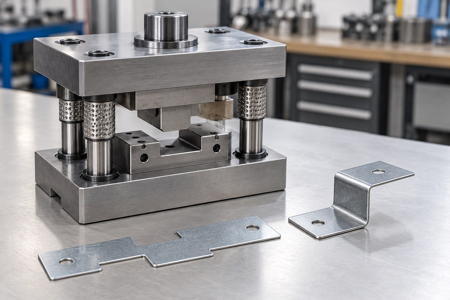
A single station die performs the agreed work at one station. Many single hit dies perform one main operation, with the part moved to another tool for a later operation. Specify the actual cutting or forming work rather than relying on the tool label alone.
A single-station route uses a discrete operation or separate stage dies. A progressive die keeps the work on a connected strip moving through several stations. Compare the whole route: demand, stock format, handling, press and feed equipment, changes, tooling and recurring part cost.
They describe different aspects. Single-station identifies the station arrangement; a compound blanking die can combine cutting operations such as blanking and piercing at one station in one stroke. Confirm the included operations, part support and required accuracy.
Consider single hit stamping dies when the part needs a defined separate operation, staged development, a secondary feature or a route with discrete blanks. Demand alone does not decide the answer. Compare setup, handling, tooling changes and acceptance with the alternatives.
A single station die quote should separate design, die set, punches and inserts, purchased components, tryout stock, sample inspection, corrections, spares and delivery. Single hit die cost depends on the actual geometry, material, press requirements and approval scope.
Agree the start conditions and separate design approval, material procurement, machining, treatment, assembly, tryout, correction and delivery. Quote a project schedule after the drawing, material, receiving press and acceptance scope are defined.
Send controlled part CAD and a dimensioned drawing, stock grade and thickness, critical datums, burr and finish requirements, quantities and receiving-press information. Add current blank or sample details for secondary operation dies. Request an NDA before sharing confidential files.
There is no one life figure for every tool. Stock abrasiveness, thickness, cutting geometry, punch and die material, setup, maintenance and sharpening affect service life. Agree wear limits, replaceable components, records and any contractual duty before ordering.
Clarify the wording. Here, steel blanking die, aluminum blanking die, stainless steel blanking die and copper blanking die identify the sheet being worked. The punch and die steel specification is a separate decision, with its grade and condition stated explicitly.
Review what changes between parts. Interchangeable punches, inserts or controlled stops may support an agreed family, but each variant needs its own identification and acceptance. Do not assume a common die set makes every geometry compatible.
Identify the sample, stock and setup. Review cutting-edge condition, clearance, alignment, stripping and location before authorizing a change. Confirm whether the drawing defines burr side, burr limit and the measurement method.
State whether you need a delivered tool, a tool retained for part production, or both. Review the Metal Stamping page for the part-production scope and keep tool ownership, tooling charges and recurring part charges separate.
FOR YOUR STAMPING PROGRAM
Keep the tooling purchase separate from recurring part-production charges.
Operation, layout and approved revisions.
Die set, punches, inserts and bought-in parts.
Press, feed, handling and scrap interfaces.
Stock, sample quantities and trial conditions.
Datums, measurements, edge and fit checks.
Responsibility, charges and repeat sampling.
Drawings, service, storage and retrieval.
Spares, preservation, packing and receiving trial.