
Simplify Your Design
Remove work that adds no useful function.
Core manufacturing processes for your prototypes, low-volume and repeat production.
Advanced manufacturing and engineering support for your complex, tight-tolerance parts.
Plan inspection, documentation and delivery around your production program.
Choose air- or liquid-cooling components around your thermal and mechanical requirements.
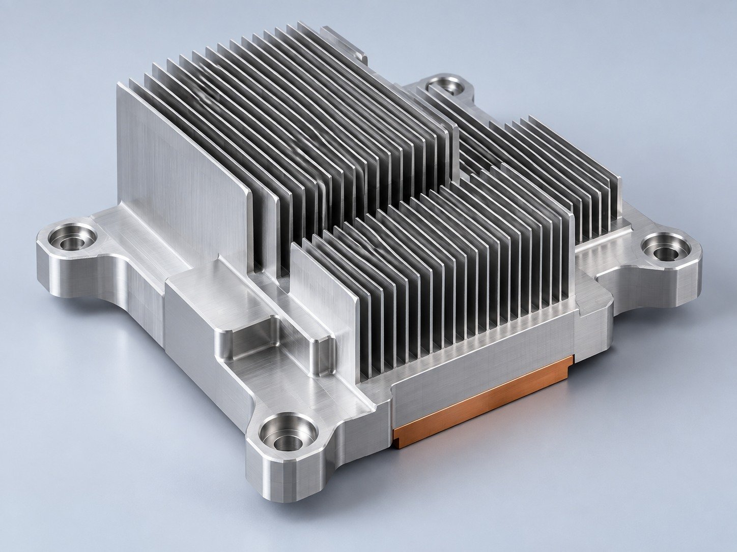
Manufacturing support for your cold plates, manifolds and cooling assemblies.
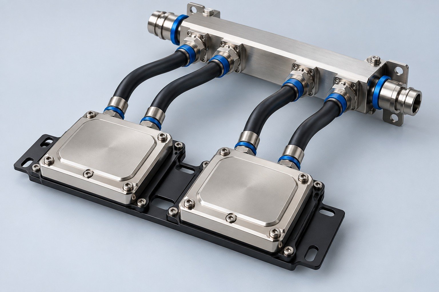
Find components for your power electronics, energy, laser and telecom application.
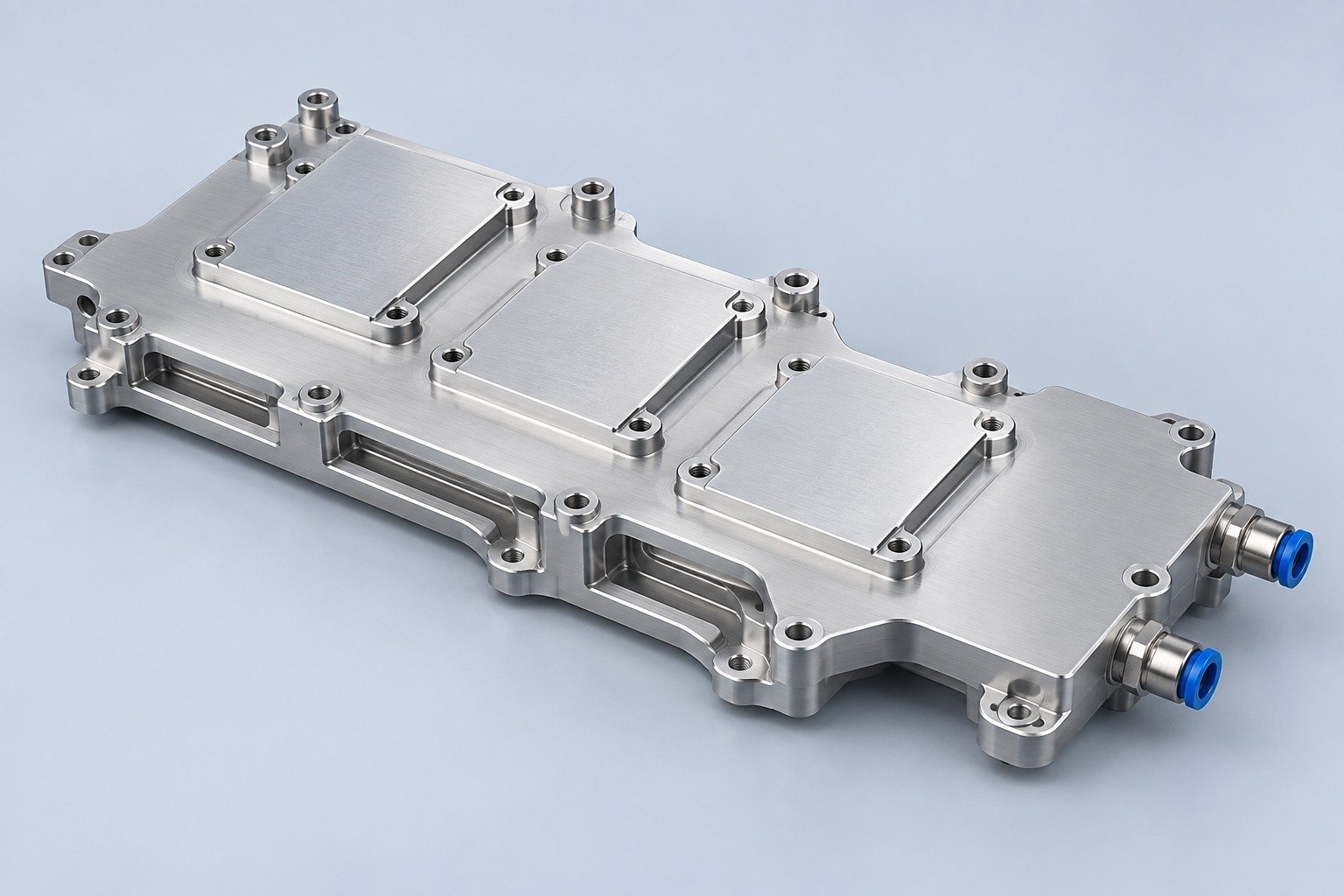
Components for your electronic systems.
Start with your functional and quality requirements.
Build around your operating environment.
Review grade, temper and finish for your metal parts.
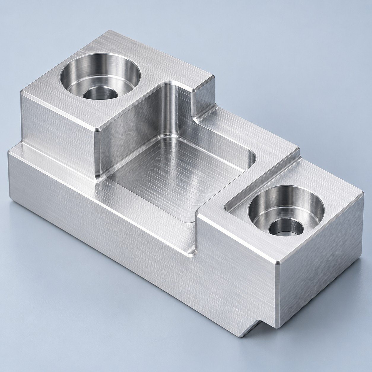 AluminumStrength, weight and machining
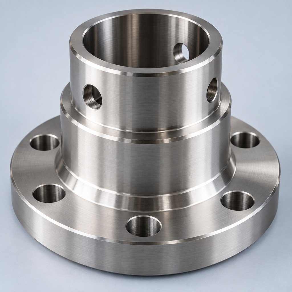 Stainless SteelCorrosion and finish requirements
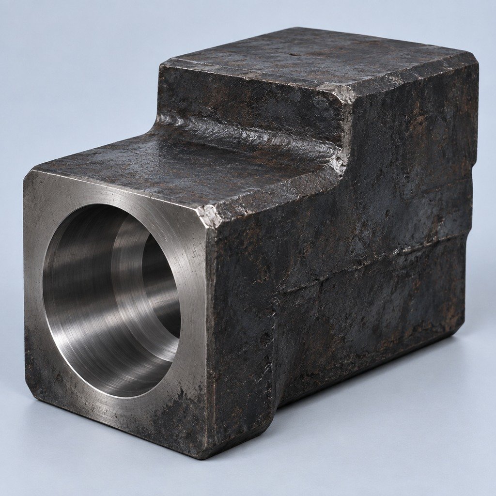 Carbon & Alloy SteelDiscuss grade and heat treatment
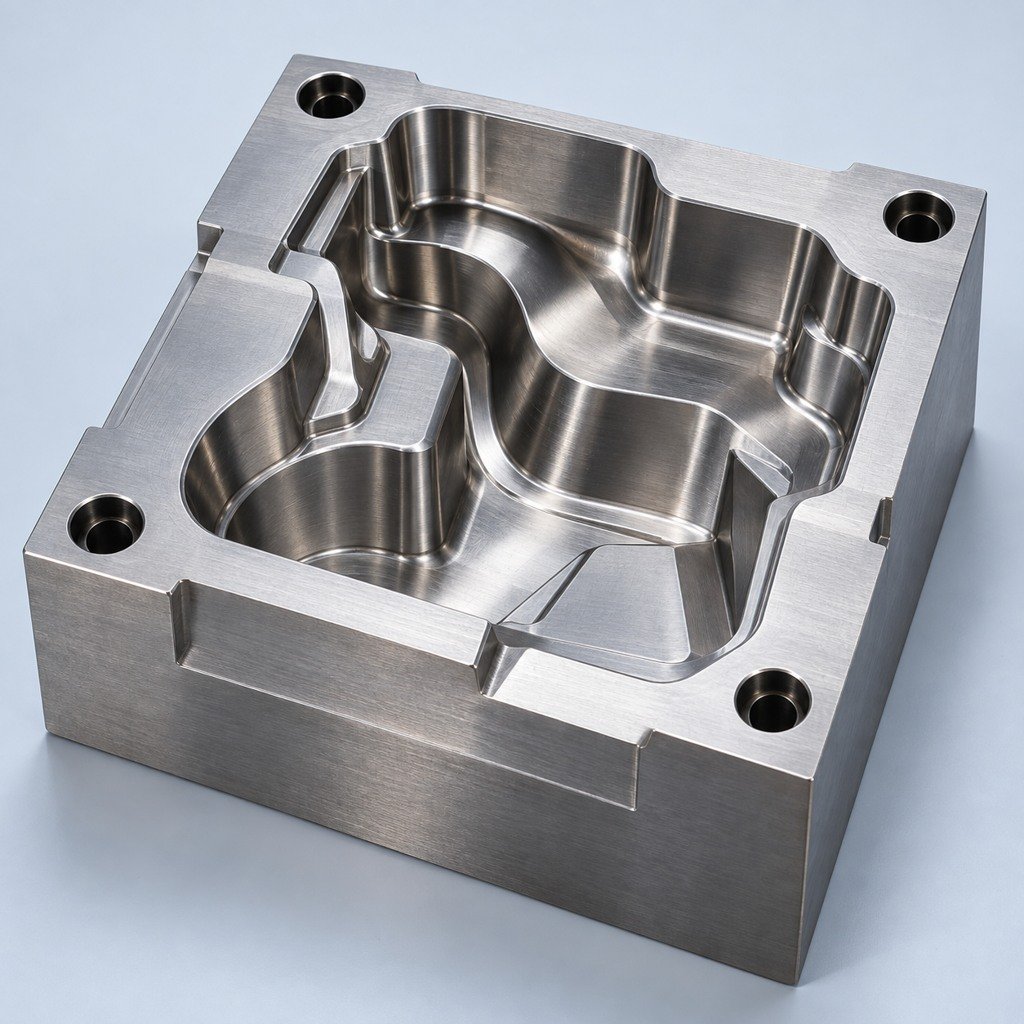 Tool SteelDiscuss tooling and wear needs
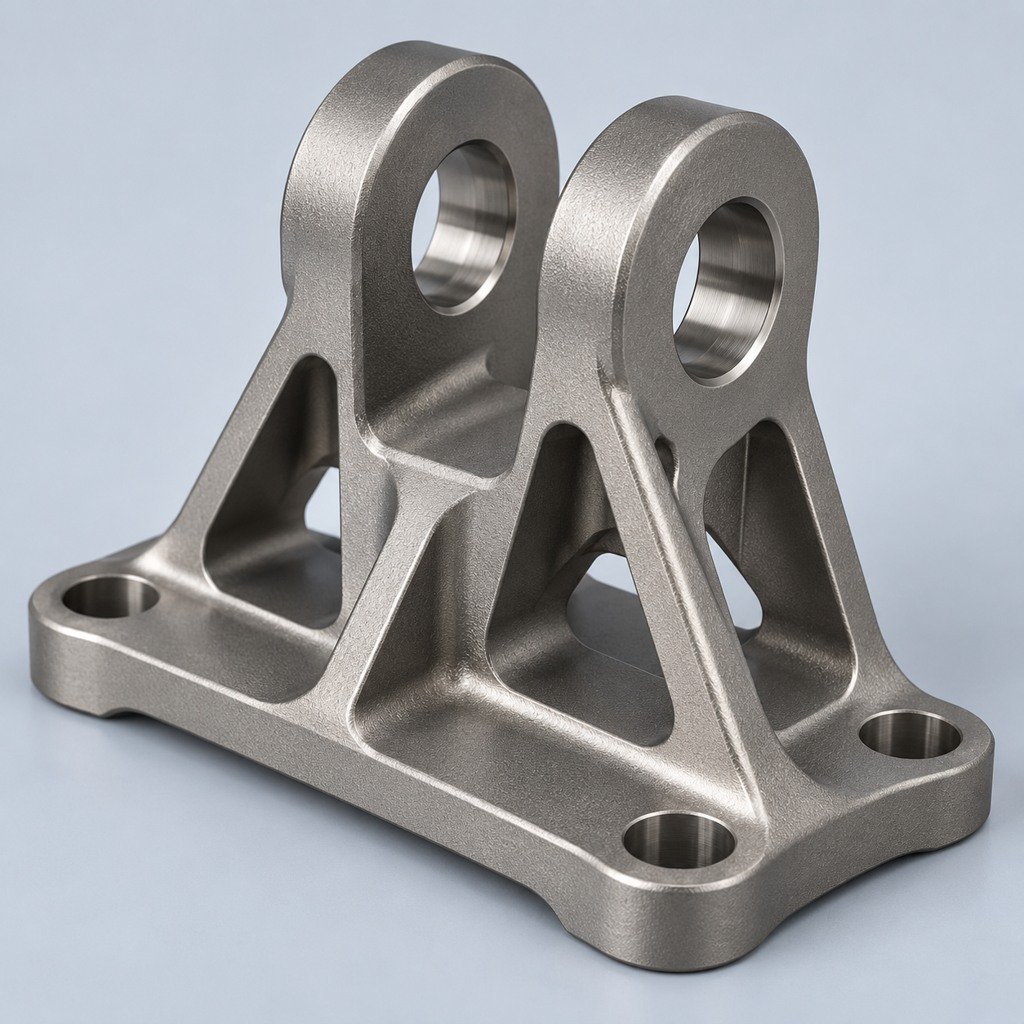 TitaniumReview grade and part geometry
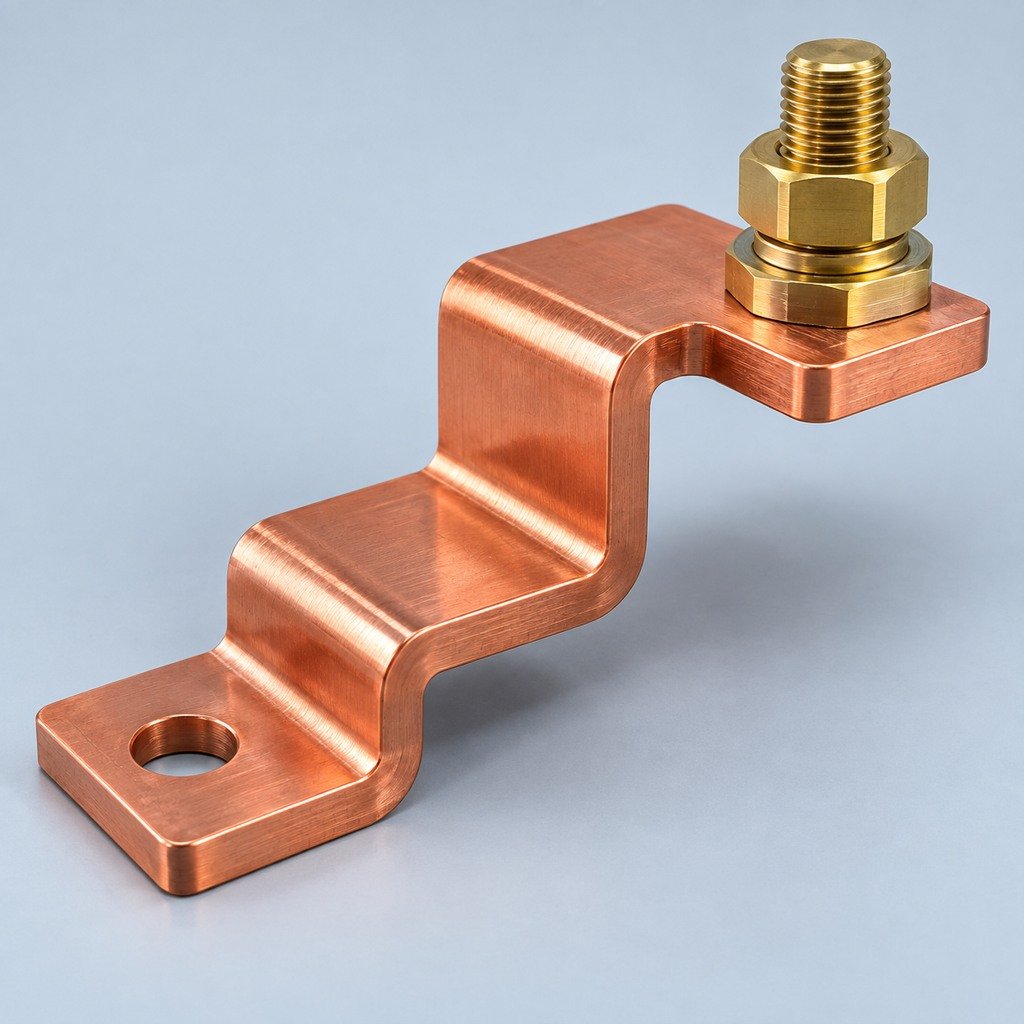 Copper & BrassDiscuss conductivity and machining
Match your polymer to function, process and environment.
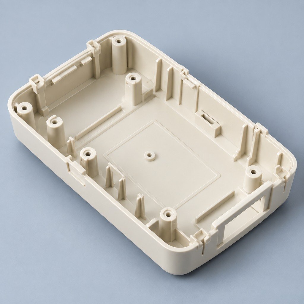 ABSReview enclosure and molding needs
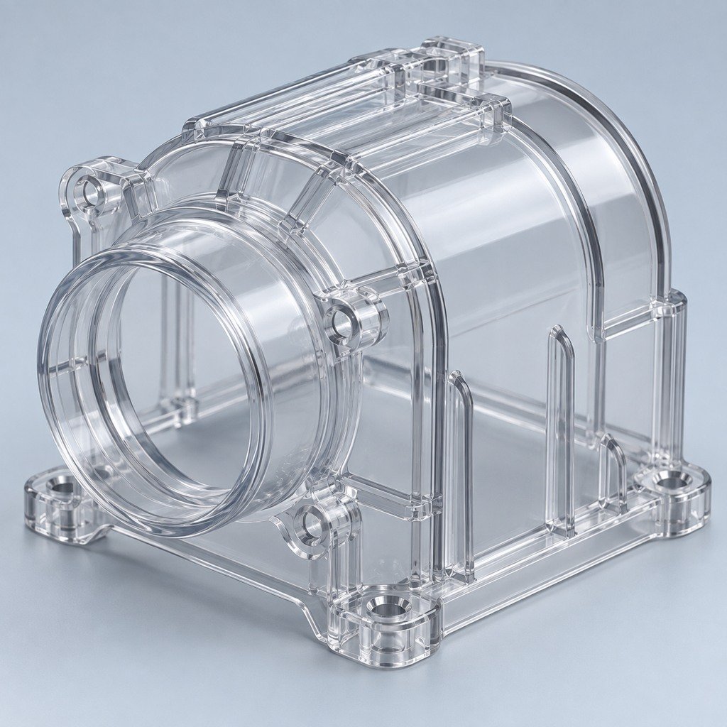 Polycarbonate (PC)Discuss clarity and impact needs
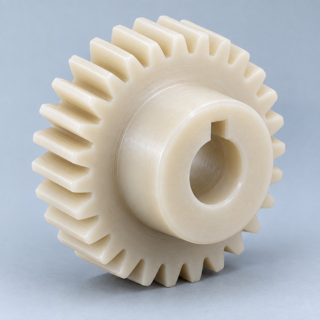 Nylon (PA)Review moisture and wear conditions
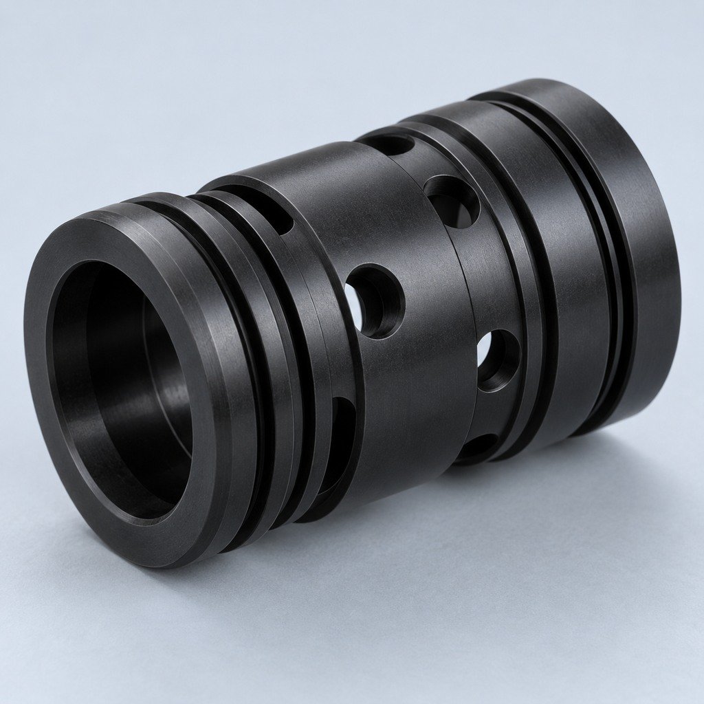 POM / AcetalReview fit and sliding features
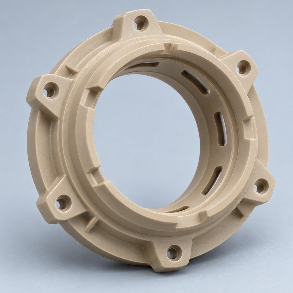 PEEKDiscuss operating conditions
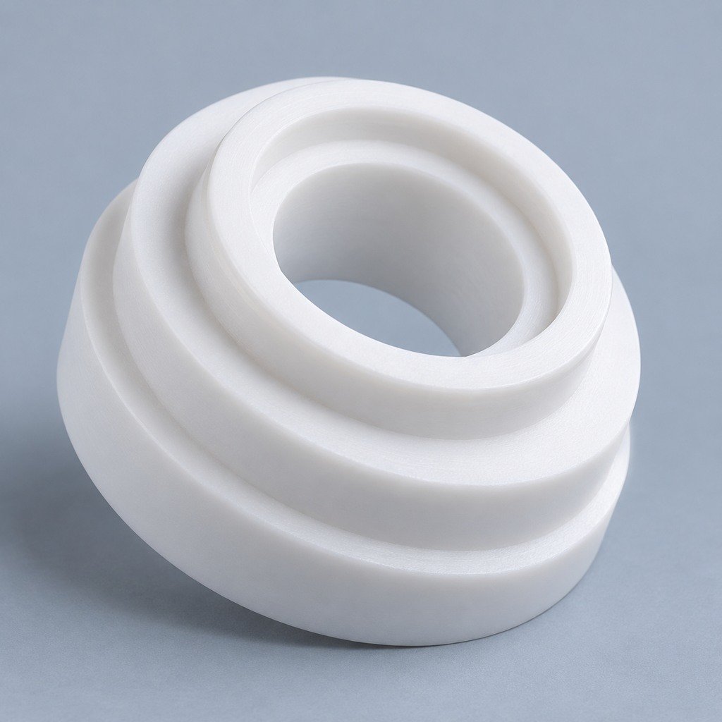 PTFEReview friction and chemical exposure
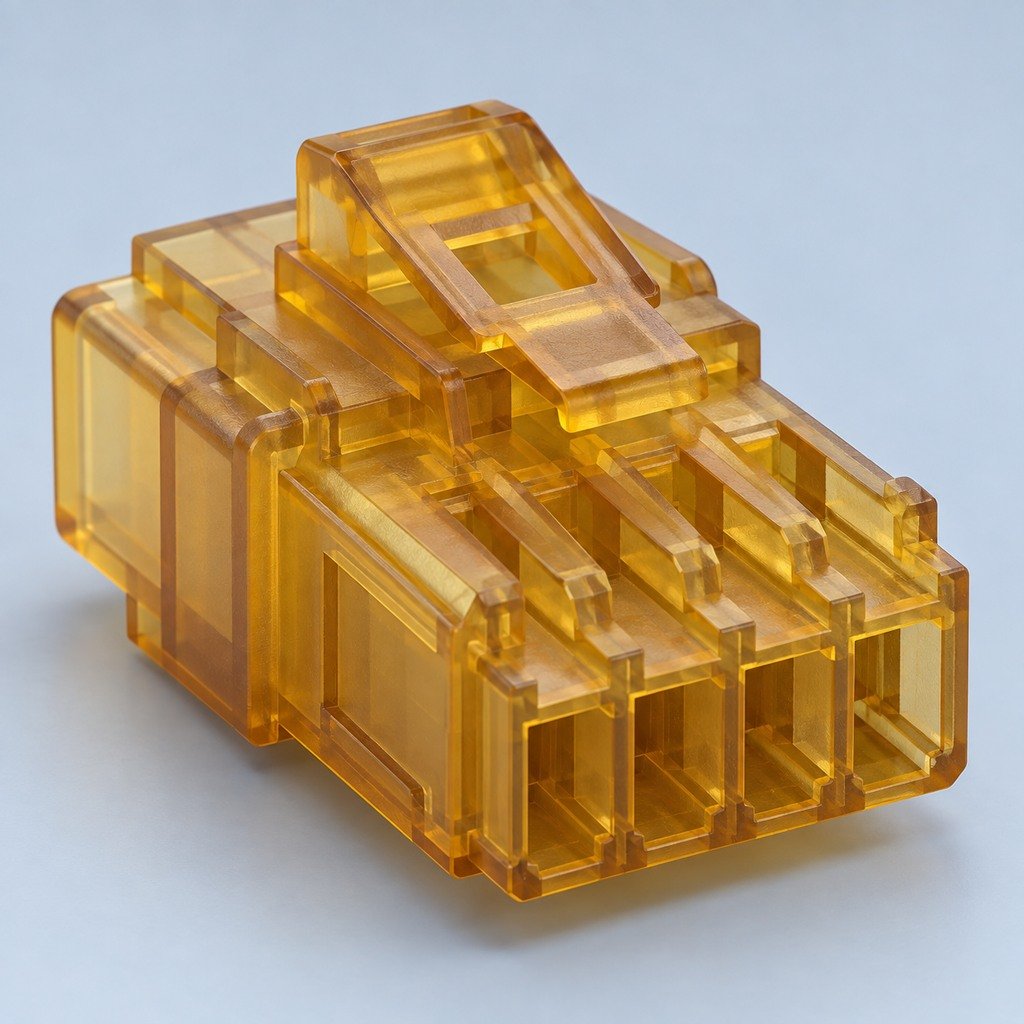 ULTEM / PEIDiscuss thermal and electrical needs
Confirm grade availability and application requirements.
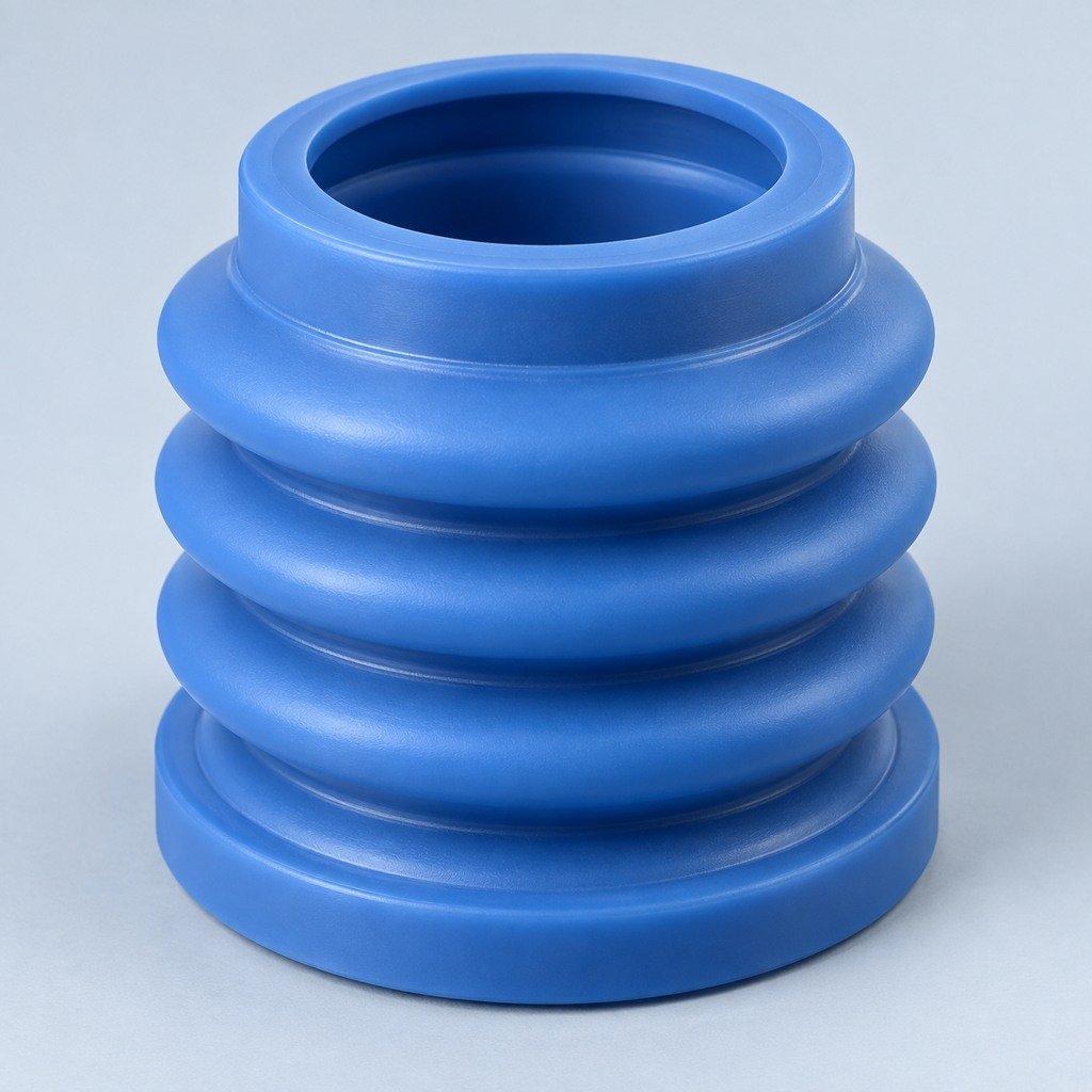 Silicone / LSRDiscuss flexible component needs
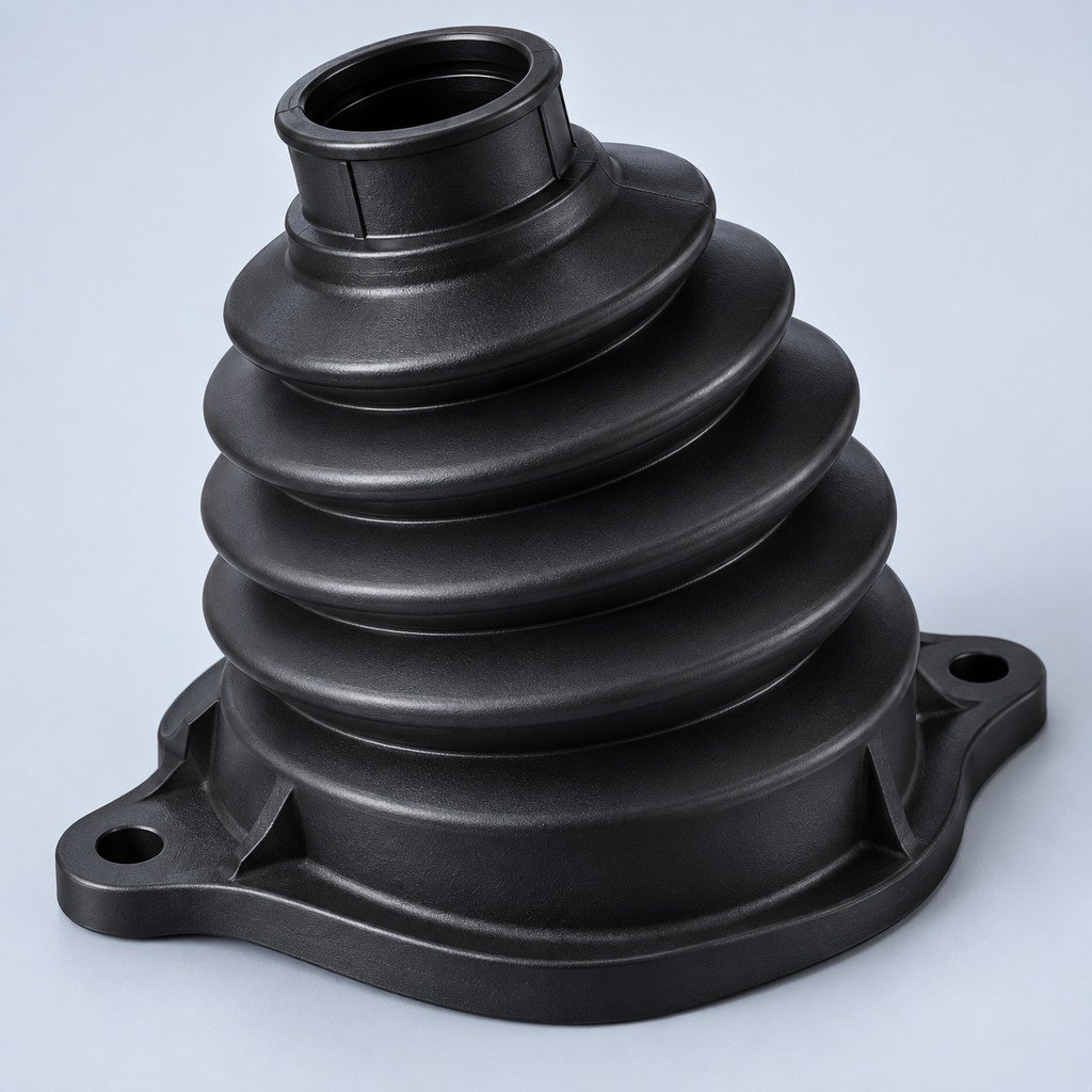 TPU / TPEReview flexibility and processing
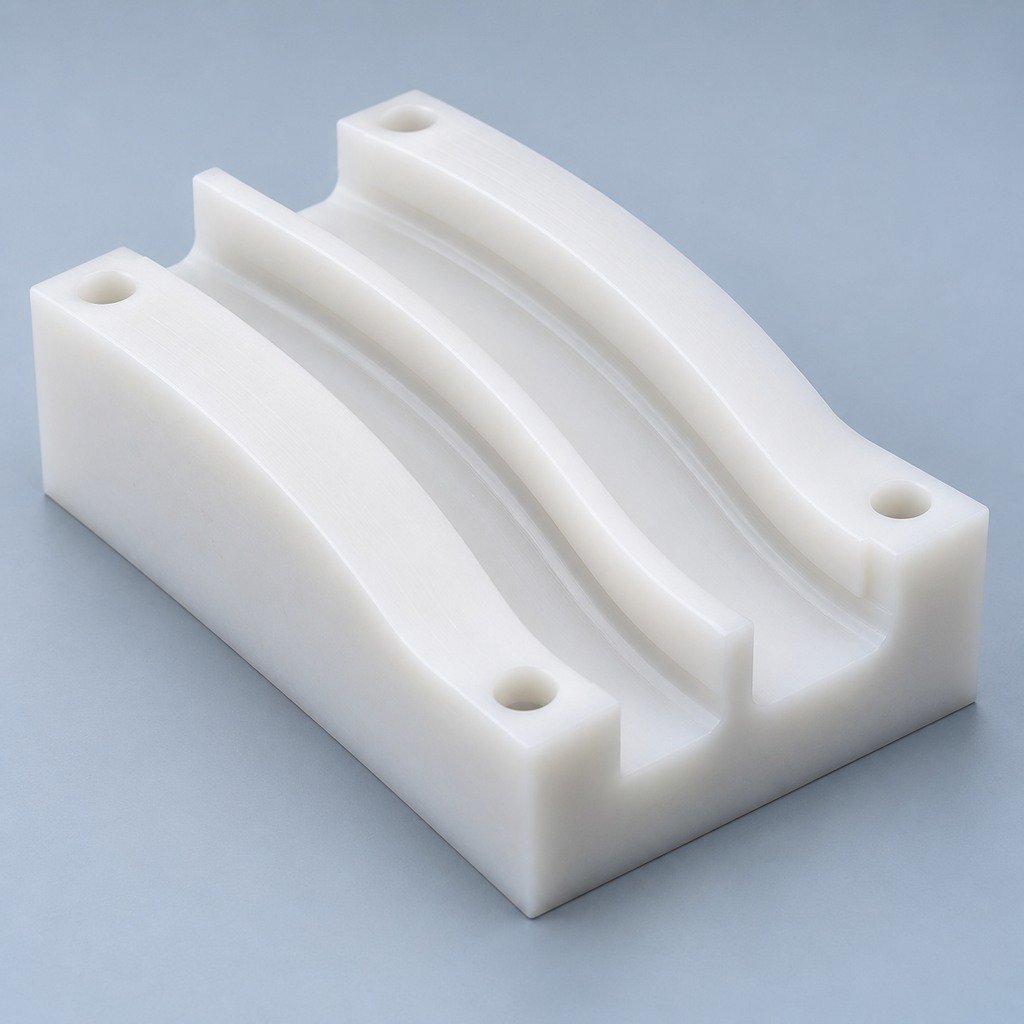 UHMW-PEDiscuss sliding and wear needs
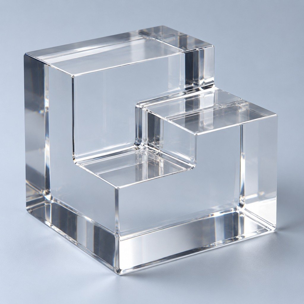 Acrylic / PMMAReview optical and cosmetic needs
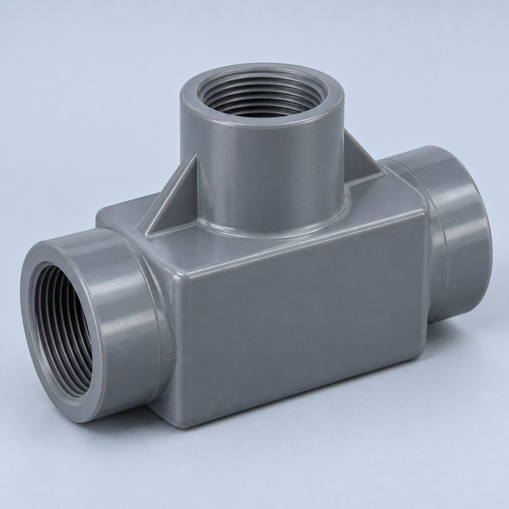 PVCDiscuss chemical exposure and grade
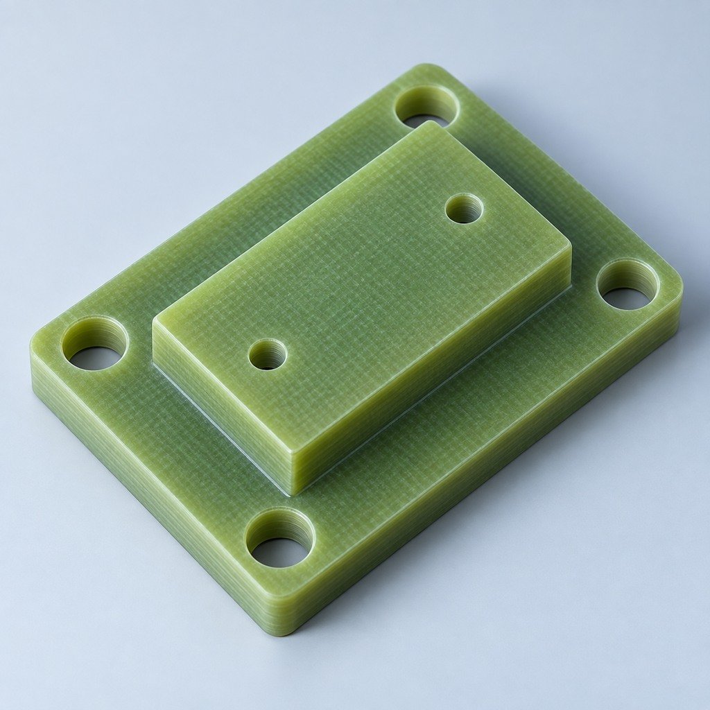 G10 / FR4Review insulation and laminate needs
Practical guidance for your part geometry and material decisions.
Prepare your process, budget and sourcing questions.
Build your knowledge before production.
Learn who we are and how we operate.
Find our U.S. support team or start a conversation.
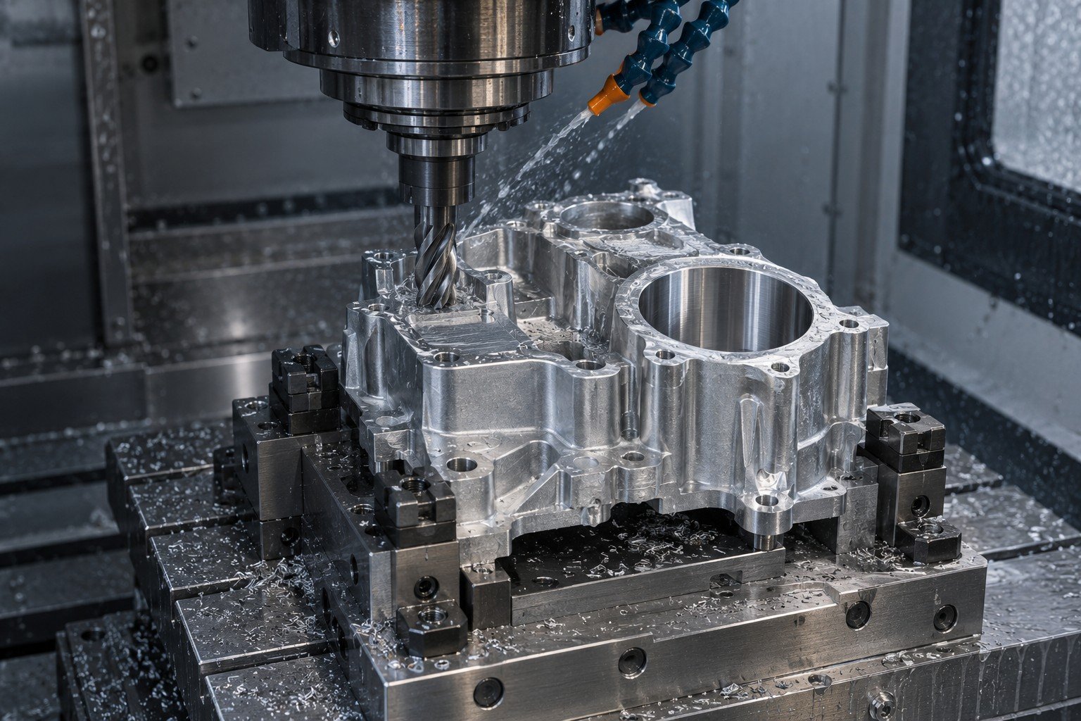
CNC MACHINING · DESIGN & COST
Spend less on avoidable machining work. Keep the features, material and inspection evidence your part actually needs.
← Engineering BlogRemove work that adds no useful function.
Include finishing, inspection and delivery.
Agree what must remain unchanged.
Release the correct drawing revision.
Your price includes more than the time a cutter touches metal. Material preparation, programming, fixtures, machine setup, deburring, surface treatment, inspection and packing can all change the result. Compare quotations against the same drawing revision and acceptance scope before treating the lowest unit price as the lowest project cost.
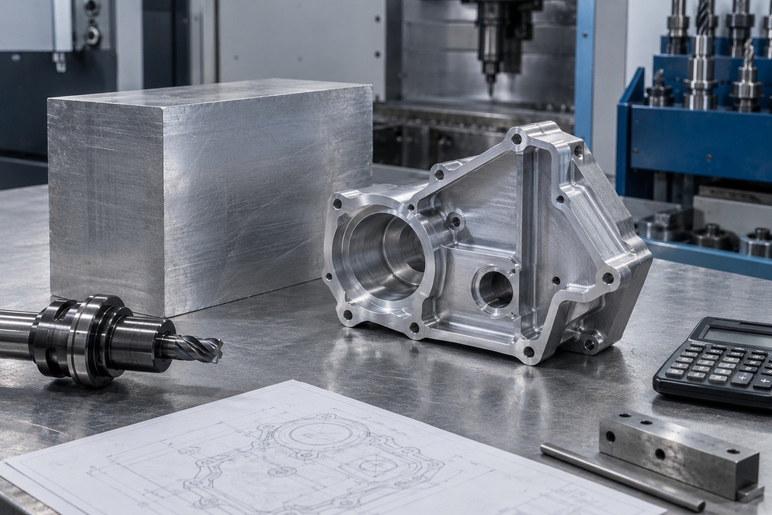
When your mating component allows clearance, a larger internal corner radius can make tool access easier. A sharp inside corner may require another process or a separate relief feature. Ask your supplier to review the corner, pocket depth and tool reach together; a radius cannot be chosen from a generic number alone.
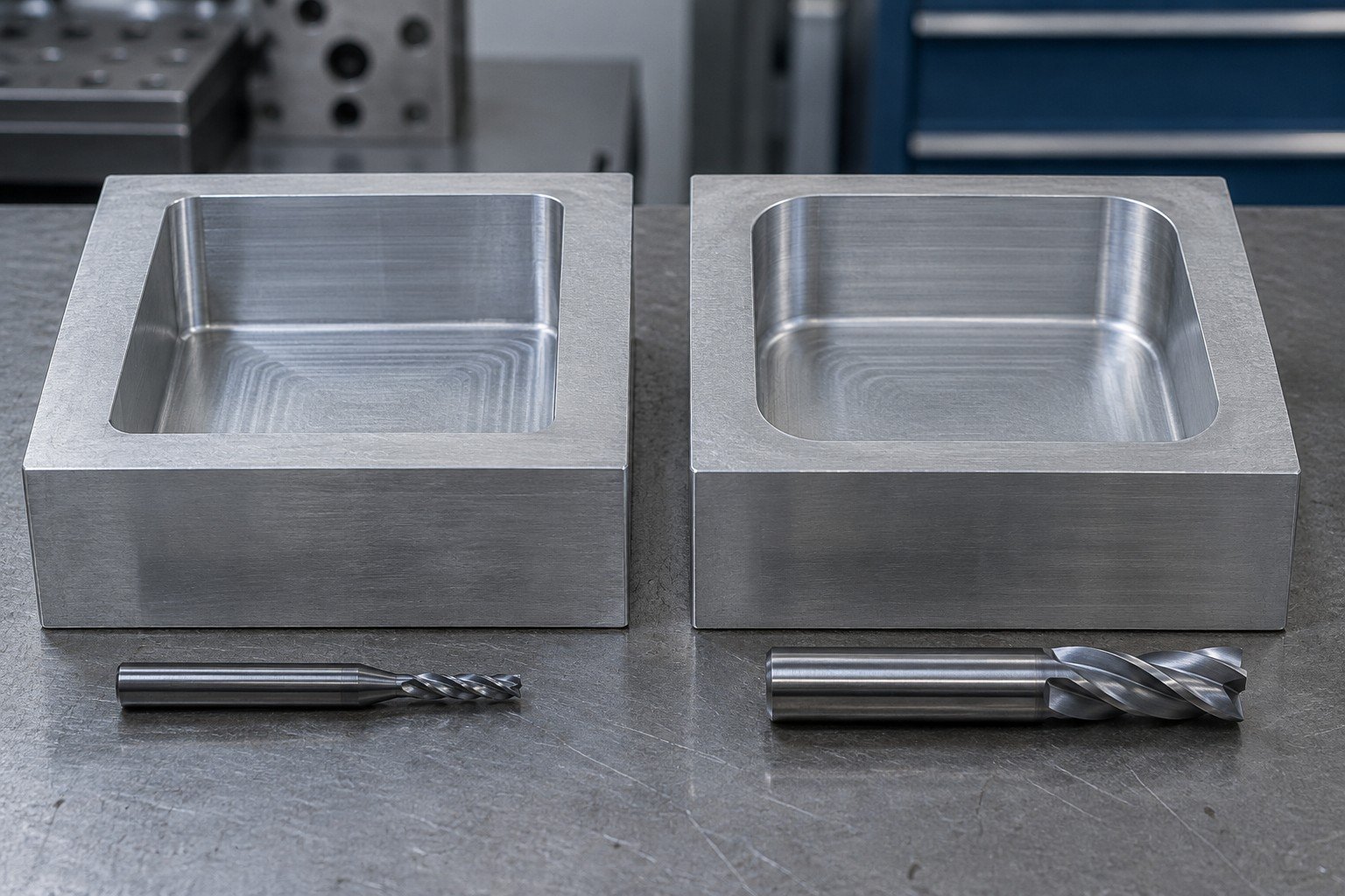
Look for features that cannot be reached with a short, rigid tool. If the depth serves no assembly or clearance purpose, compare a shallower pocket. For a long hole, ask whether access from a second face is possible and how the resulting alignment will be verified. Confirm breakthrough, thread engagement and chip clearance before changing the drawing.
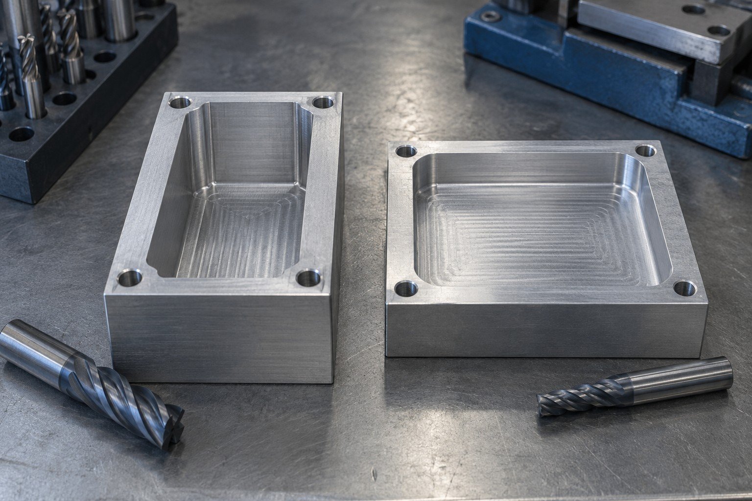
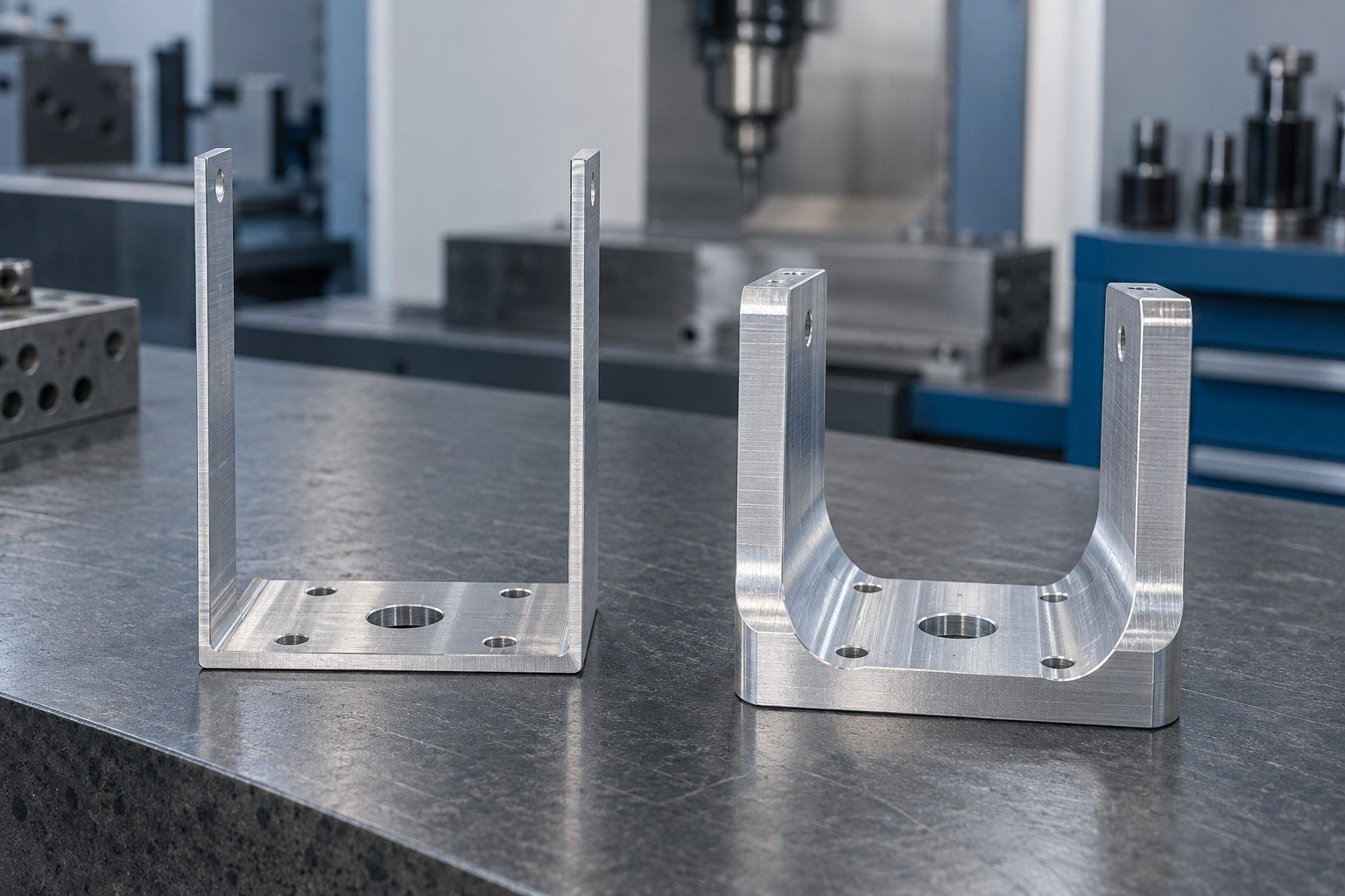
A thin wall may need extra support or a different machining sequence. Review both the finished shape and how the part stays supported while material is removed. A local rib, a thicker noncritical area or a different stock condition may be worth comparing; each change needs a check against weight, fit and operating loads.
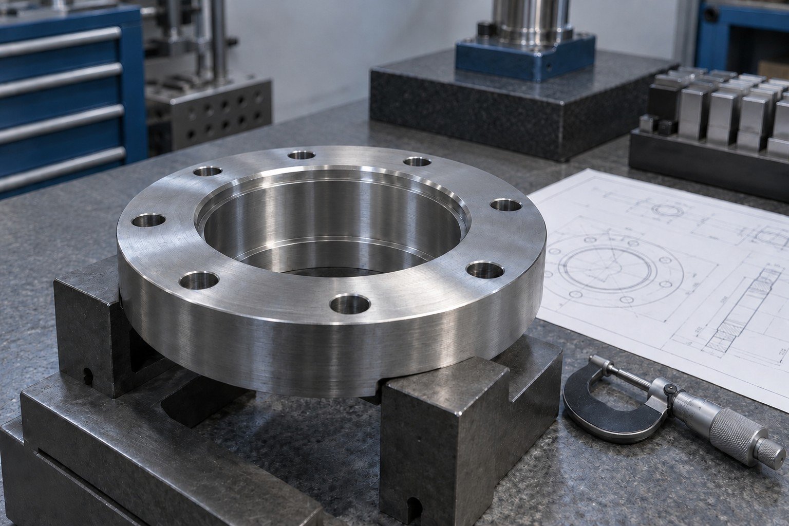
Start with the interfaces that determine performance: a bearing seat, sealing face, locating datum or mating pattern. Tell your supplier which features are critical, how the part is referenced and what inspection evidence you need. Unnecessary tight callouts can add manufacturing and measurement work.
Start with your temperature, load, wear, corrosion, electrical and weight requirements. Then compare material availability, stock shape, machining, finishing and documentation. Your aluminum CNC machining program and a stainless steel CNC machining program may need different tools and schedules; comparing raw material price alone misses the rest of the work.
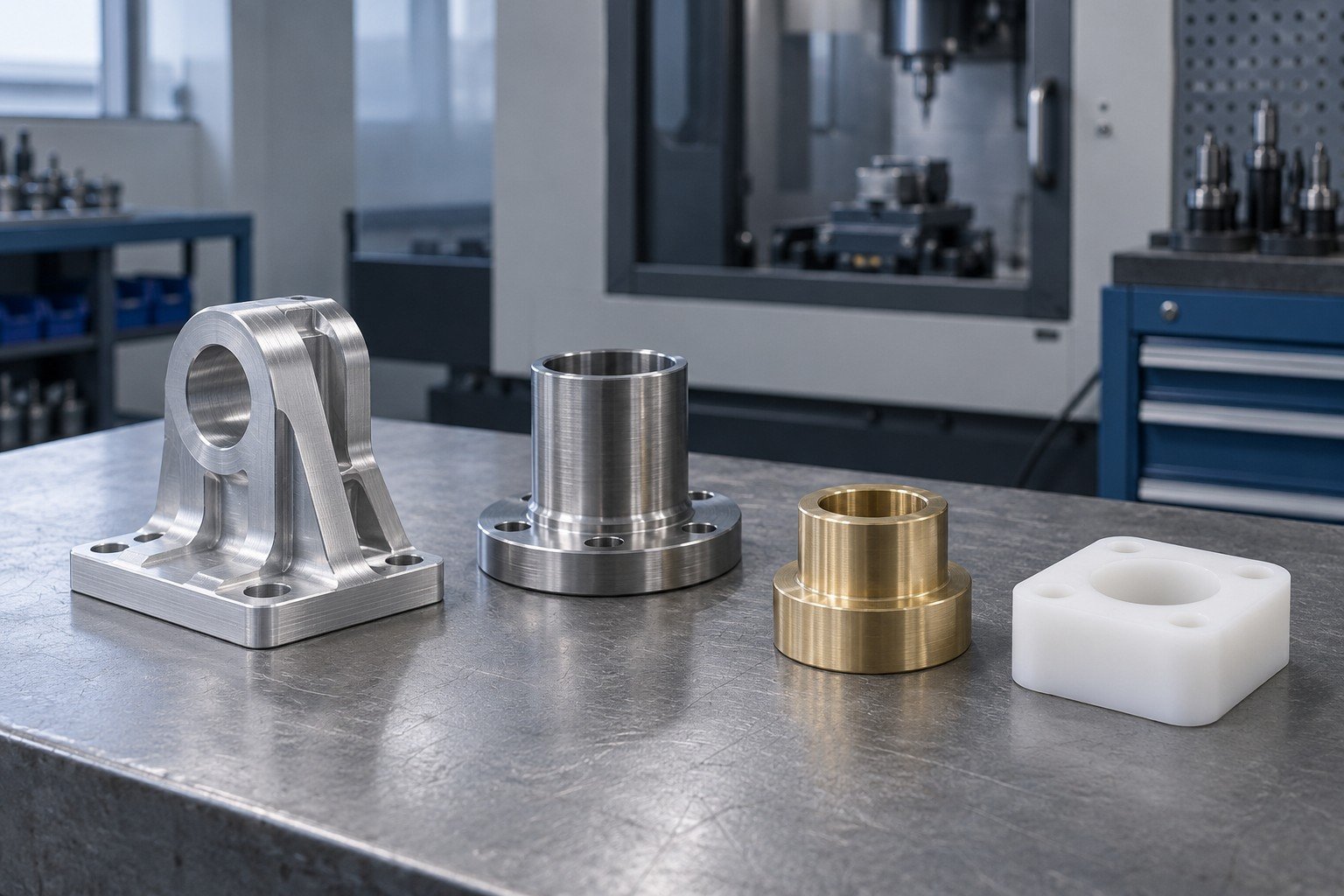
| Material family | Useful review question | Protect in your specification |
|---|---|---|
| Aluminum | Can an available grade and stock shape meet your design? | Alloy, temper, finish and strength needs |
| Stainless steel | Which corrosion and service conditions govern the grade? | Grade, condition and surface requirements |
| Brass | Does the selected grade fit your machining and service needs? | Composition and application restrictions |
| Engineering plastics | How do load, temperature and moisture affect the fit? | Exact grade, stability and acceptance condition |
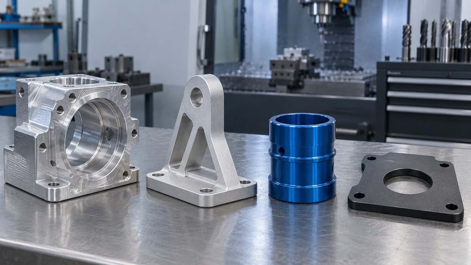
Identify the job each finish performs: corrosion protection, appearance, wear, electrical behavior or a required surface texture. Keep cosmetic requirements focused on visible areas when that suits your design. Your drawing should state masking, contact faces and the dimensions that must remain acceptable after treatment.
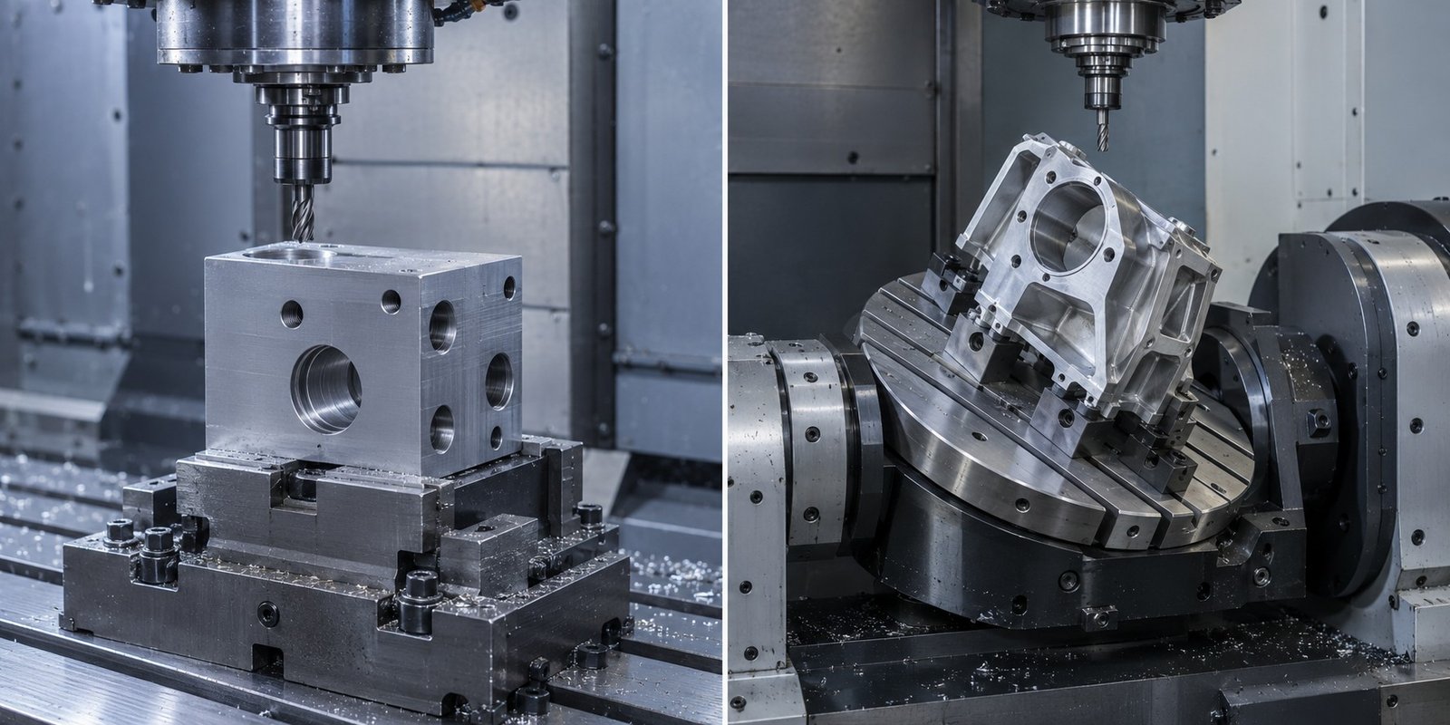
Choose the route by tool access, setups, required accuracy and total work. A prismatic part may be straightforward on a 3-axis machine. Multiple angled interfaces may justify reviewing 5-axis CNC machining services. More axes do not automatically make a part cheaper; the proposed fixture, operations and measurement plan matter.
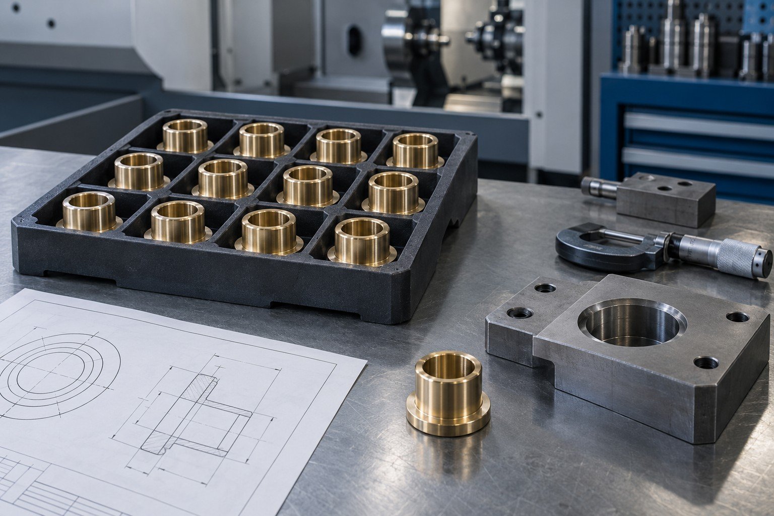
Your initial quantity and expected repeat demand influence the production plan. Ask for comparable price breaks using the same revision and scope. For high volume CNC machining, capacity, dedicated fixtures and repeat inspection may matter as much as the first batch price. Your forecast helps the discussion; it is not a purchase commitment.
This is arithmetic with your own assumptions, not an LK MFG quotation. It excludes material, machining time, finishing, inspection, scrap and shipping.
Setup cost per part = assumed setup cost ÷ batch quantity. Currency is whichever unit you entered.

A useful design for manufacturability review connects your part’s purpose with a proposed route. Ask your precision machining services supplier to separate required changes from optional cost opportunities. Your team retains control of the drawing and acceptance criteria.
There is no useful fixed percentage for every part. Ask for a quotation comparison that shows the changed requirement, price and tradeoff. Keep function and acceptance evidence in the same review.
Only when the alternative meets your application. Check strength, temperature, corrosion, wear and finishing needs; your engineering team approves the grade change.
A larger batch may spread setup cost, but it also increases purchased quantity and inventory exposure. Compare the amount you need, repeat demand and the full order value.
Review noncritical callouts, but retain the limits your fit and performance require. Record any approved change in your drawing revision.
Review it when angled features, tool access or repeated reclamping affect the route. Ask for the operations and inspection plan rather than selecting solely by machine name.
Send your CAD, controlled drawing, material grade, finish, quantities, critical requirements, inspection scope and delivery target. Include the question you want the review to resolve.
Compare general machining guidance with your own drawing and supplier review: Protolabs: machining design considerations; Xometry: CNC cost factors; Xometry: tolerance planning. Their published service limits are not LK MFG guarantees.