

Injection Molding
Tooling and molding for your repeat plastic parts.
From prototype to production, coordinated manufacturing solutions for your custom parts.
View All Services →
Precision parts for your tight tolerances and complex geometry.
Tooling and molding for your repeat plastic parts.

Metal casting options for your part and production volume.

Cutting, forming and welding for your fabricated parts.

Custom profiles for your section, length and finish requirements.

Finishes for your appearance, corrosion and wear requirements.

Sub-assemblies and final builds for your production program.

Production tooling built around your process and volume.

Prototype parts to check fit, function and design.
DFM, process planning and production support for your project.
Inspection, documentation, inventory and delivery planning for your program.
Choose air- or liquid-cooling components around your thermal and mechanical requirements.

Manufacturing support for your cold plates, manifolds and cooling assemblies.

Find components for your power electronics, energy, laser and telecom application.

Components for your electronic systems.
Start with your functional and quality requirements.
Build around your operating environment.
From prototype to production, review material performance, manufacturability and cost for your part.
Review grade, temper and finish for your metal parts.
 AluminumStrength, weight and machining›
 Stainless SteelCorrosion and finish requirements›
 Carbon & Alloy SteelDiscuss grade and heat treatment›
 Tool SteelDiscuss tooling and wear needs›
 TitaniumReview grade and part geometry›
 Copper & Brass & BronzeDiscuss conductivity and machining›
Match your polymer to function, process and environment.
 ABSReview enclosure and molding needs›
 Polycarbonate (PC)Discuss clarity and impact needs›
 Nylon (PA)Review moisture and wear conditions›
 POM / AcetalReview fit and sliding features›
 PEEKDiscuss operating conditions›
 PTFEReview friction and chemical exposure›
 ULTEM / PEIDiscuss thermal and electrical needs›
Confirm grade availability and application requirements.
 Silicone / LSRDiscuss flexible component needs›
 TPU / TPEReview flexibility and processing›
 EPDMReview weathering and chemical exposure.›
 NBRReview oil and fuel exposure.›
 FKMReview temperature and chemical exposure.›
 G10 / FR4Review insulation and laminate needs›
 CompositesReview stiffness, weight and laminate.›Customer-Specified MaterialsConfirm your grade and requirements.›Other Specialty MaterialsDiscuss your application and grade.›
Practical guidance for your part geometry and material decisions.
Prepare your process, budget and sourcing questions.
Build your knowledge before production.
Learn who we are and how we operate.
Find our U.S. support team or start a conversation.

For your C52100 machining inquiry, start with the feature that must stay springy and the surface that must locate. Define strip or bar, supplied temper, mounting support and acceptance before agreeing a cutting or forming route.
For your C52100 phosphor bronze 8% selection, specify the complete product requirement. C52100 chemical composition and temper identify different decisions: alloy acceptance and the supplied state of your stock.
| Your callout | What to confirm |
|---|---|
| UNS C52100 | Wrought phosphor bronze; exact product standard required. |
| CuSn8 / CW453K | Producer comparison for European drawings; full limits govern. |
| Bar or strip | Drawn-product and strip standards describe different products; specify the full ordered requirements. |
For C52100 bronze properties, keep bar and strip references separate. Cu + named elements ≥99.5% is a combined total. Aurubis PNA 283 strip uses Sn 7.5–8.5%, with its own other limits, rather than the selected drawn-product range.
| Selected element | Drawn-product reference · wt.% |
|---|---|
| Tin | 7.0–9.0 |
| Phosphorus | 0.03–0.35 |
| Lead | ≤0.05 |
| Zinc | ≤0.20 |
| Iron | ≤0.10 |
| Copper | Remainder |
Concast ASTM B139/B139M-12(2024) reference; other ordered requirements apply. Not a lot analysis report.
Concast references · common scale 0–10
Free-cutting brass = 100 · common scale 0–100
Selected Concast drawn-product data; indices do not predict your cutting time, cost or spring life. Aurubis PNA 283 strip rates machinability as not recommended. Treat that strip guidance separately from the indicative bar index of 20 and agree your actual route. C54400 has a different leaded chemistry; no automatic substitution is implied.
Concast C52100 ↗ Concast C51000 ↗ Concast C54400 ↗ Aurubis strip reference ↗
Choose the contact, retainer, collar or formed component. Review the supported feature and final measurement state before committing to a route.
For your custom C52100 spring contacts, identify the restrained foot, moving tongues and mating contact. Agree the free shape and any contact-force or electrical test explicitly.
| Your decision | What to define |
|---|---|
| Your fit | Mounting datum, tongue spacing, contact travel and defined test points. |
| Your route | Stock condition, support and finishing sequence. |
| Your approval | Final geometry, surface and receiving evidence. |
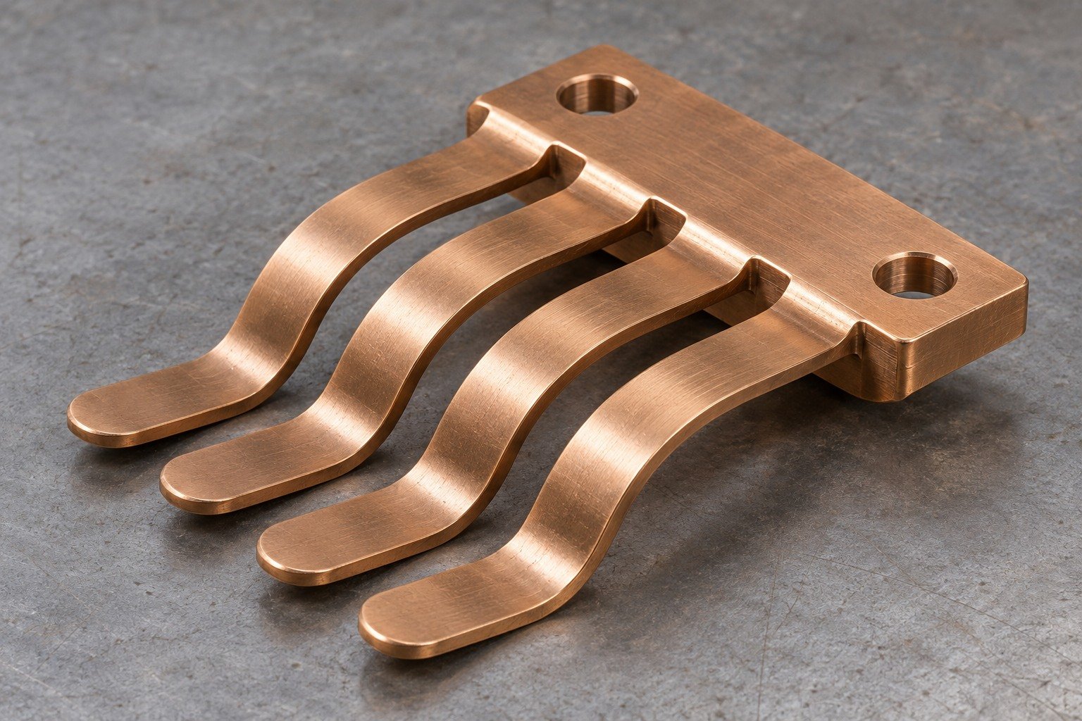
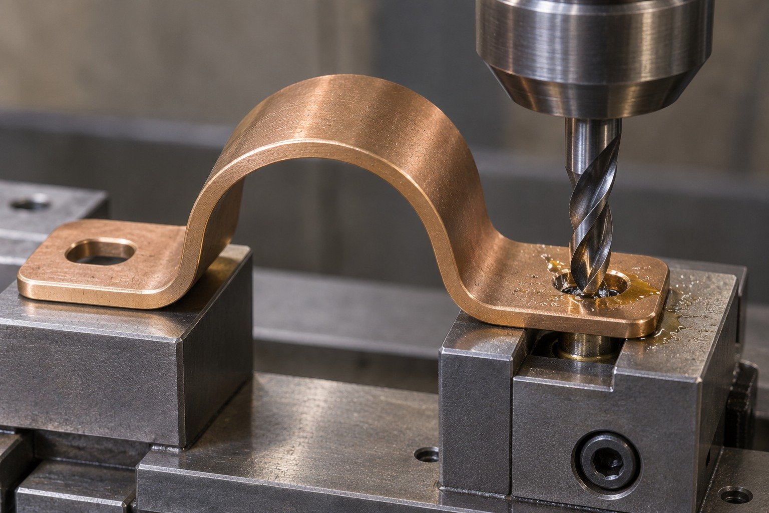
For C52100 drilling, back the mounting foot directly and keep the moving tongues outside clamping loads.
| Your decision | What to define |
|---|---|
| Your fit | Mounting datum, tongue spacing, contact travel and defined test points. |
| Your route | Stock condition, support and finishing sequence. |
| Your approval | Final geometry, surface and receiving evidence. |
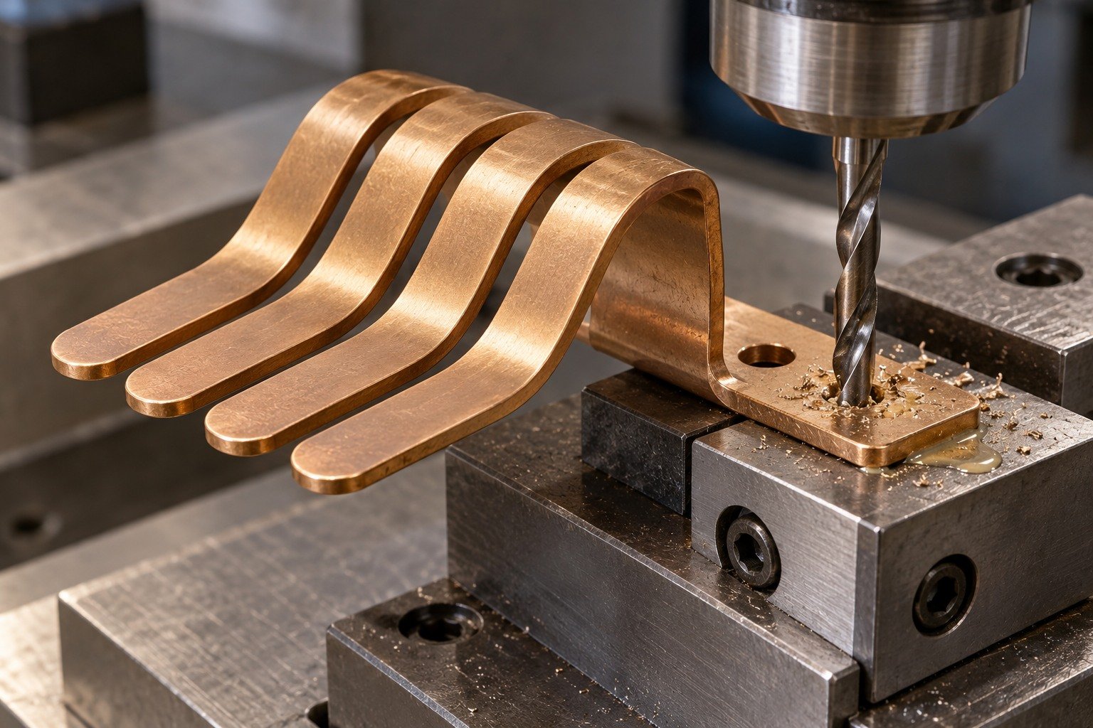
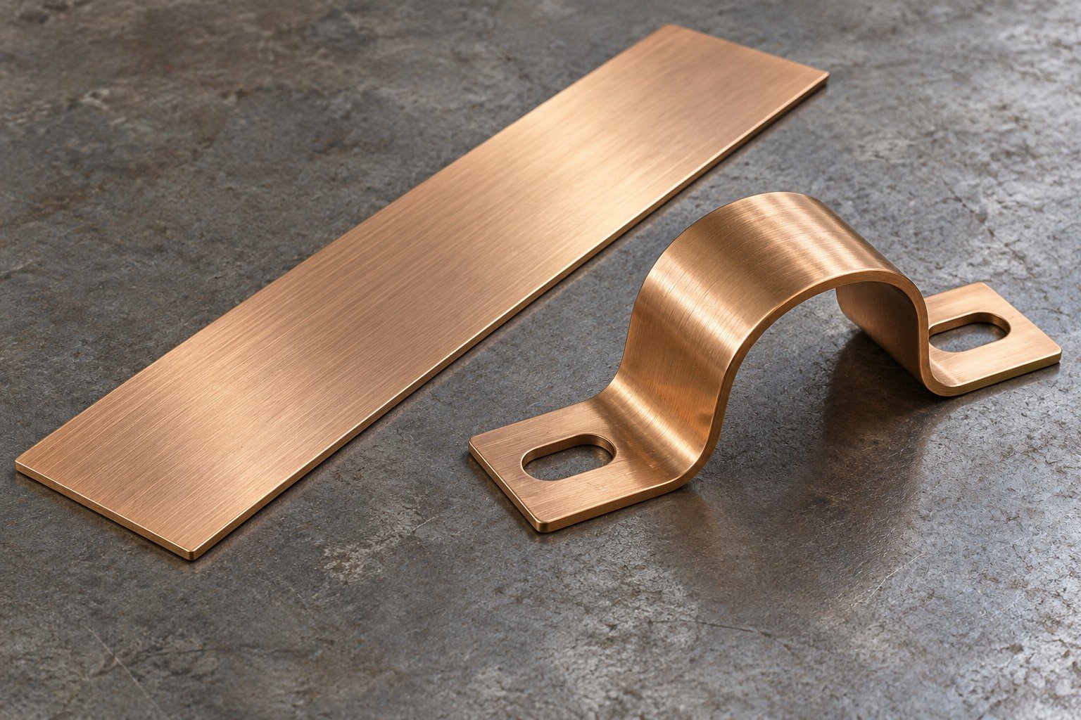
Specify strip thickness, rolling direction and C52100 spring temper using the ordered product standard.
| Your decision | What to define |
|---|---|
| Your fit | Mounting datum, tongue spacing, contact travel and defined test points. |
| Your route | Stock condition, support and finishing sequence. |
| Your approval | Final geometry, surface and receiving evidence. |
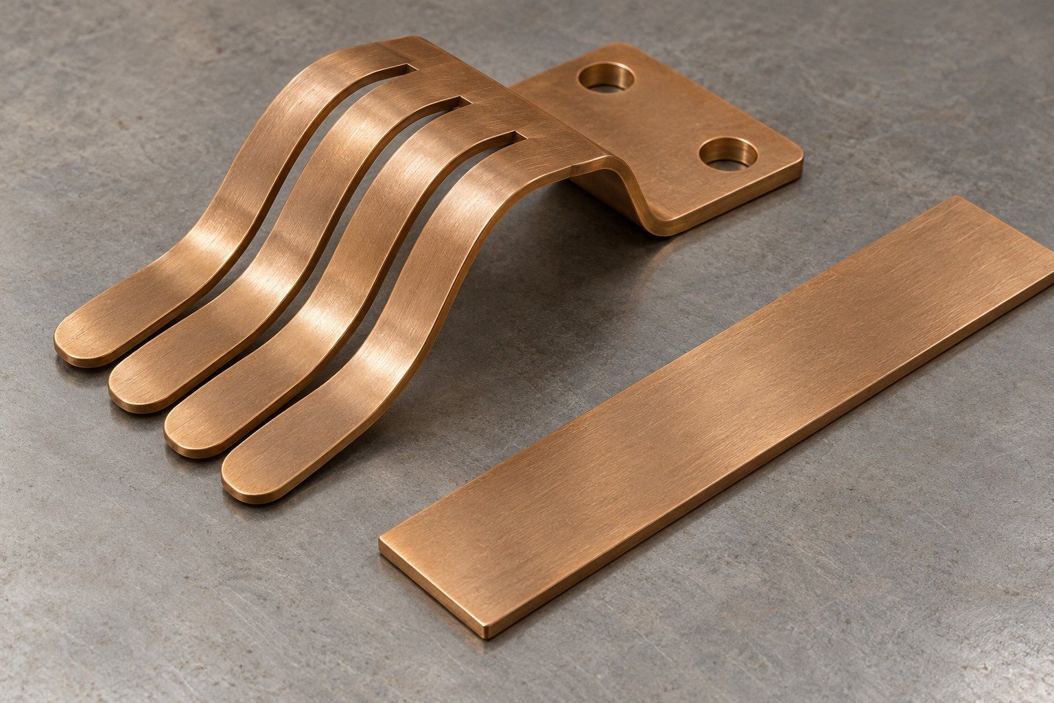
For C52100 spring contacts, separate dimensional acceptance from contact-force, resistance and fatigue testing.
| Your decision | What to define |
|---|---|
| Your fit | Mounting datum, tongue spacing, contact travel and defined test points. |
| Your route | Stock condition, support and finishing sequence. |
| Your approval | Final geometry, surface and receiving evidence. |
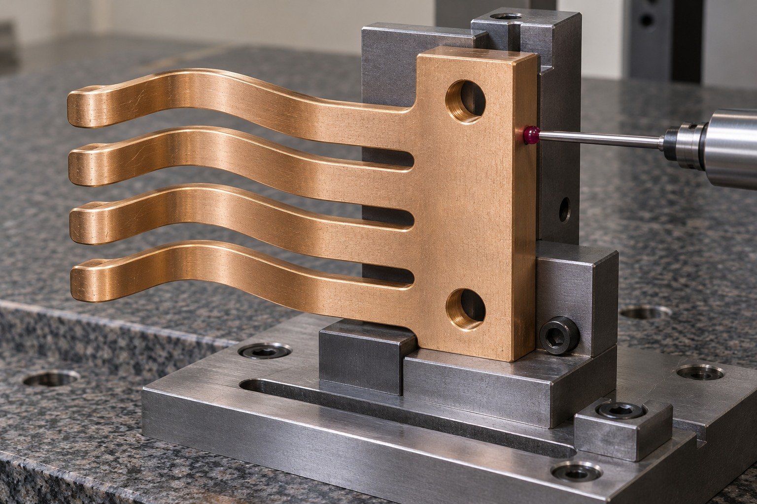
For your custom C52100 spring clips, define the installed restraint and travel. Show which geometry is accepted freely and which is accepted in an assembly fixture.
| Your decision | What to define |
|---|---|
| Your fit | Free clip shape, mounting-wing holes, installed restraint and accepted movement. |
| Your route | Stock condition, support and finishing sequence. |
| Your approval | Final geometry, surface and receiving evidence. |
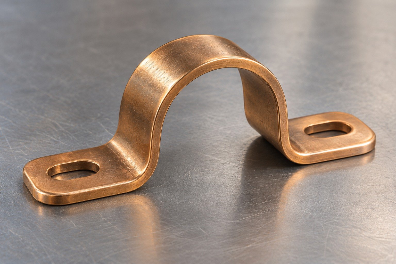
For your C52100 CNC machining review, identify limited cut features on the supported wing; do not load the unsupported arch.
| Your decision | What to define |
|---|---|
| Your fit | Free clip shape, mounting-wing holes, installed restraint and accepted movement. |
| Your route | Stock condition, support and finishing sequence. |
| Your approval | Final geometry, surface and receiving evidence. |
Confirm supplied strip temper and bend direction before tooling or forming decisions.
| Your decision | What to define |
|---|---|
| Your fit | Free clip shape, mounting-wing holes, installed restraint and accepted movement. |
| Your route | Stock condition, support and finishing sequence. |
| Your approval | Final geometry, surface and receiving evidence. |
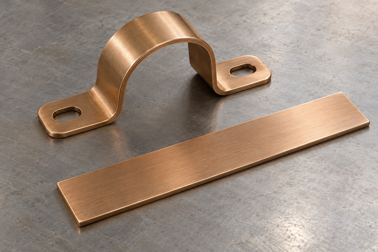
For C52100 spring clips, agree fixture, force points and measurement condition before repeating parts.
| Your decision | What to define |
|---|---|
| Your fit | Free clip shape, mounting-wing holes, installed restraint and accepted movement. |
| Your route | Stock condition, support and finishing sequence. |
| Your approval | Final geometry, surface and receiving evidence. |

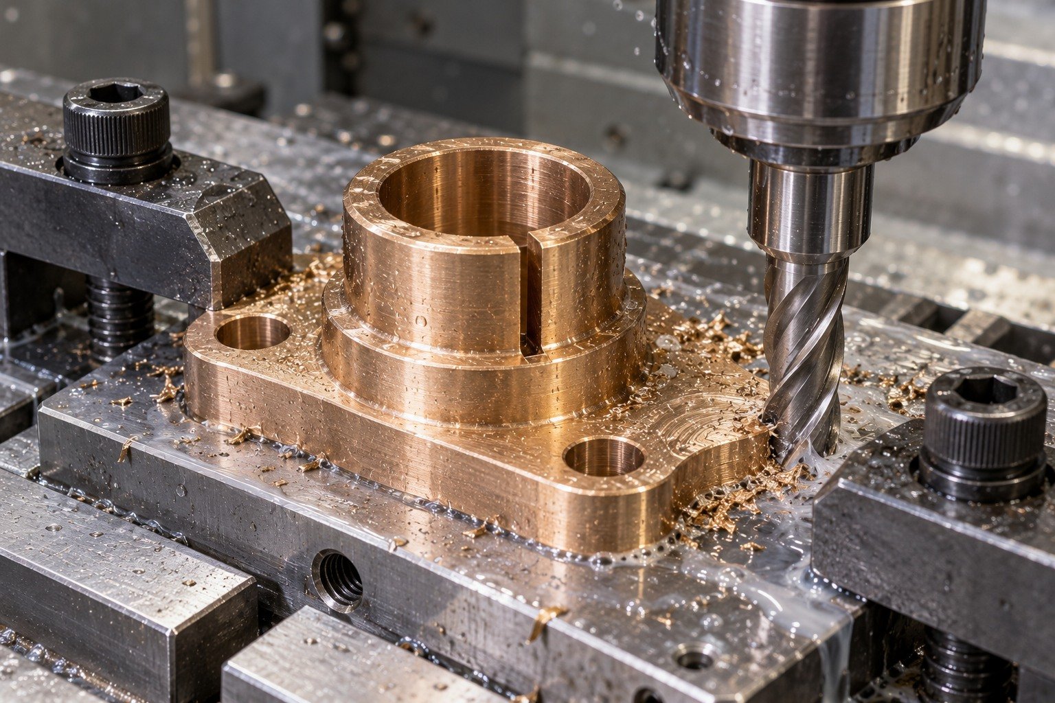
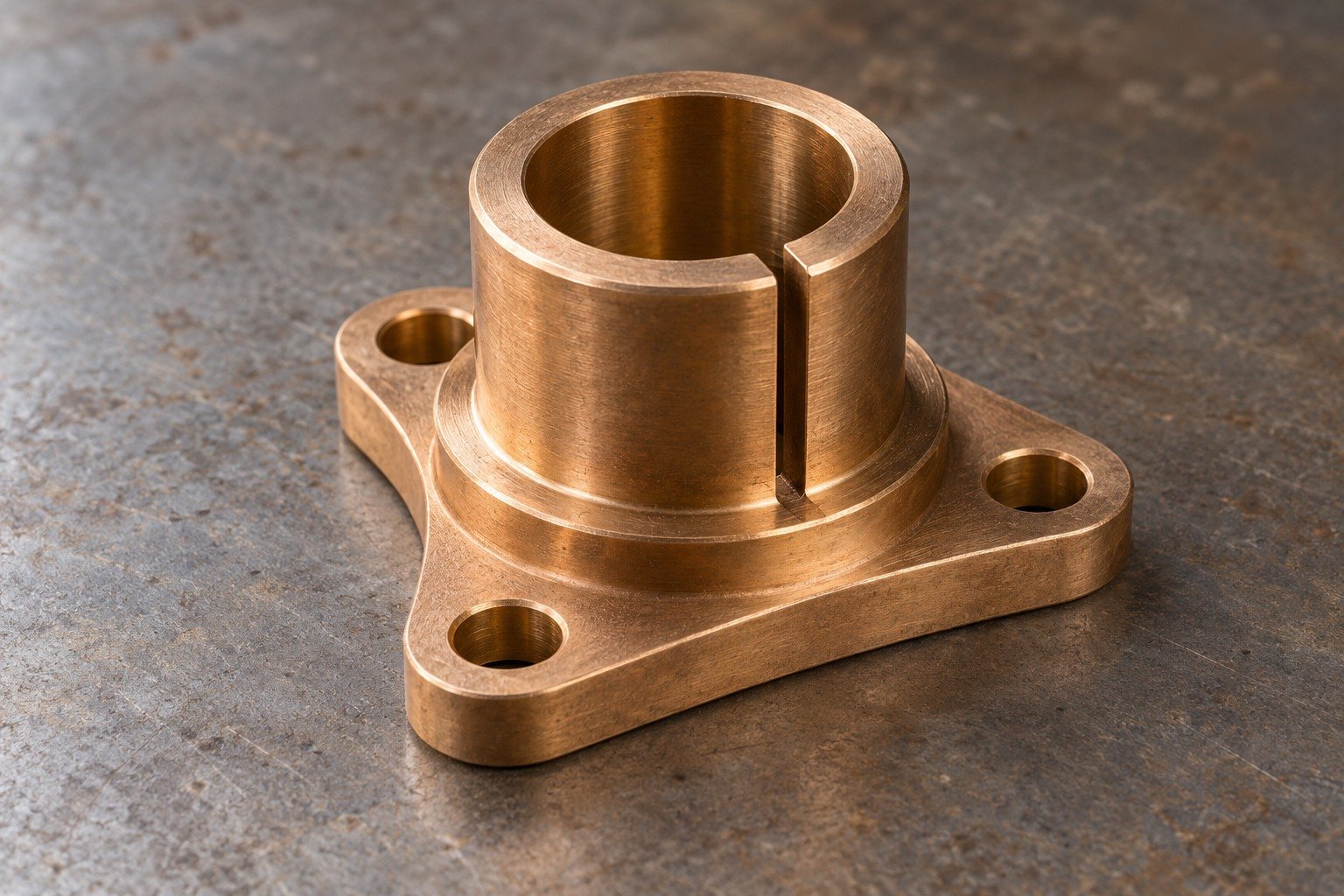
For your custom C52100 connectors, locate the open slot and shoulder from the actual attachment datum. Keep the contact surface distinct from the clamped mounting base.
| Your decision | What to define |
|---|---|
| Your fit | Connector slot, bore, shoulder and mounting-hole relationship. |
| Your route | Stock condition, support and finishing sequence. |
| Your approval | Final geometry, surface and receiving evidence. |
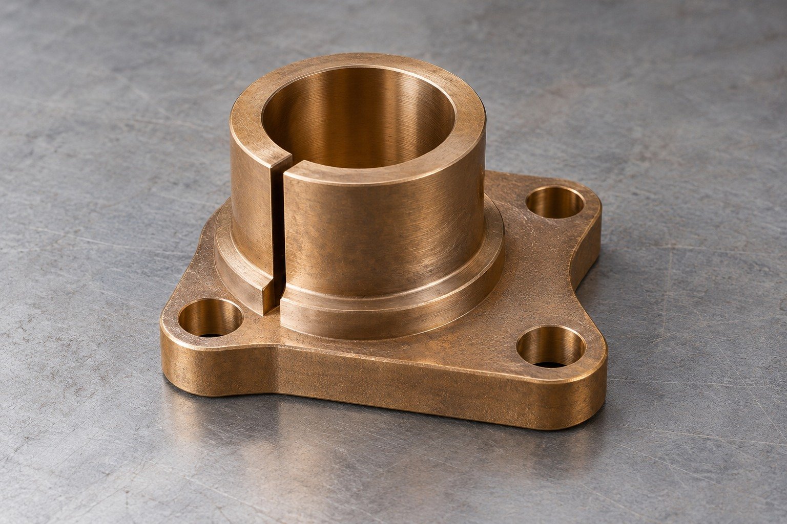
For C52100 milling, review slot access, solid base support and chip removal at internal intersections.
| Your decision | What to define |
|---|---|
| Your fit | Connector slot, bore, shoulder and mounting-hole relationship. |
| Your route | Stock condition, support and finishing sequence. |
| Your approval | Final geometry, surface and receiving evidence. |
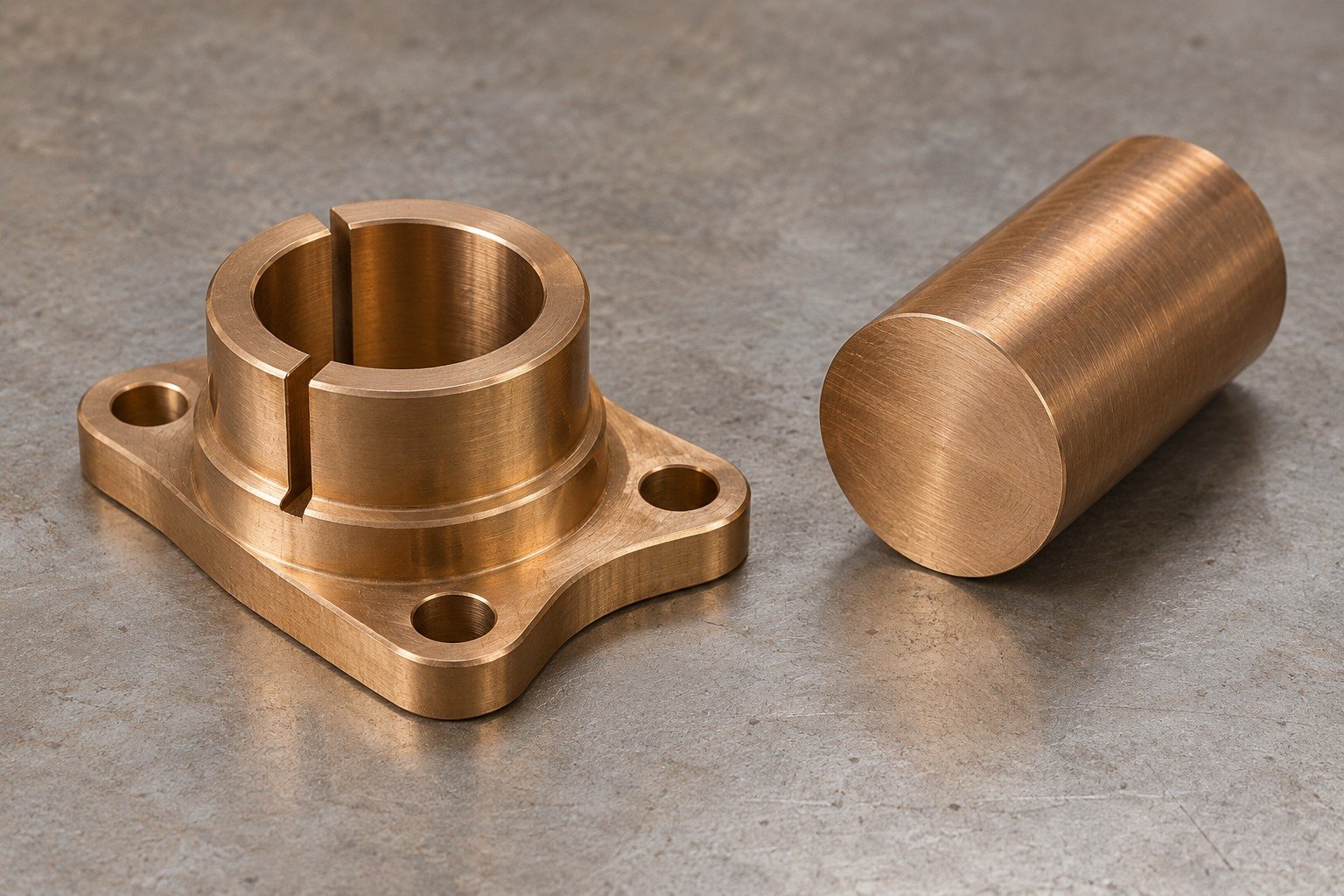
Identify round or other machining stock, supplied condition and usable allowance.
| Your decision | What to define |
|---|---|
| Your fit | Connector slot, bore, shoulder and mounting-hole relationship. |
| Your route | Stock condition, support and finishing sequence. |
| Your approval | Final geometry, surface and receiving evidence. |
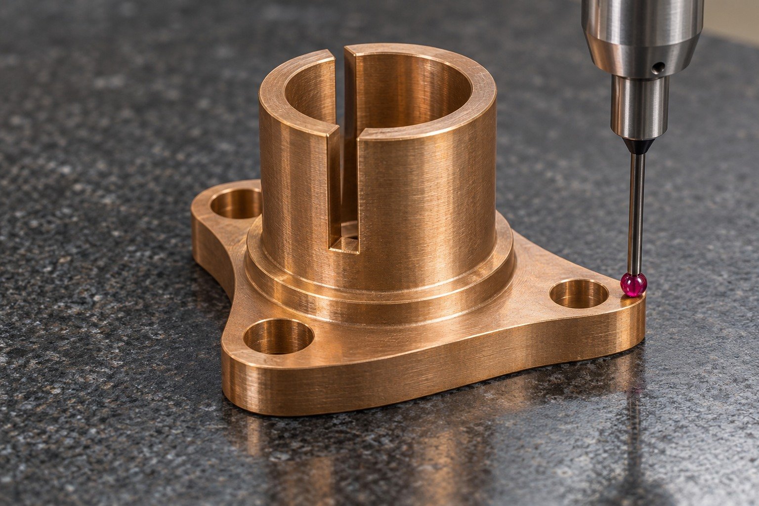
For C52100 connectors, inspect geometry first; any current, resistance or mating-force acceptance needs a defined test.
| Your decision | What to define |
|---|---|
| Your fit | Connector slot, bore, shoulder and mounting-hole relationship. |
| Your route | Stock condition, support and finishing sequence. |
| Your approval | Final geometry, surface and receiving evidence. |
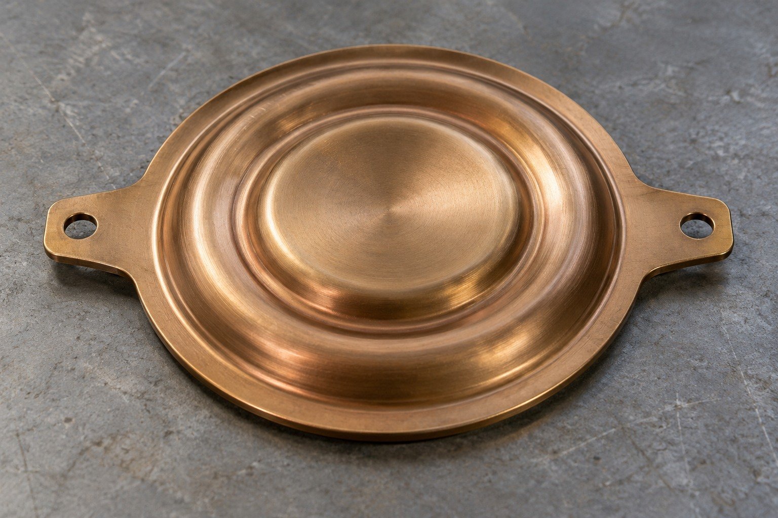
For your custom C52100 formed parts, show the blank, mounting tabs and working shape. A shallow diaphragm requires its own forming and functional review.
| Your decision | What to define |
|---|---|
| Your fit | Corrugation geometry, supported mounting tabs and working deflection. |
| Your route | Stock condition, support and finishing sequence. |
| Your approval | Final geometry, surface and receiving evidence. |
For C52100 forming and limited tab drilling, agree tool access, support and the final accepted geometry.
| Your decision | What to define |
|---|---|
| Your fit | Corrugation geometry, supported mounting tabs and working deflection. |
| Your route | Stock condition, support and finishing sequence. |
| Your approval | Final geometry, surface and receiving evidence. |
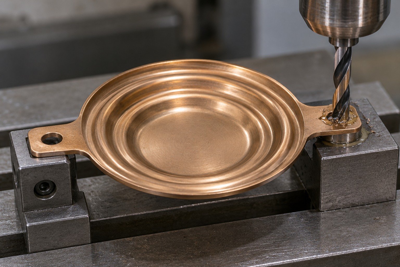
Specify strip product, thickness, supplied temper and forming sequence; do not infer stock state from alloy colour.
| Your decision | What to define |
|---|---|
| Your fit | Corrugation geometry, supported mounting tabs and working deflection. |
| Your route | Stock condition, support and finishing sequence. |
| Your approval | Final geometry, surface and receiving evidence. |
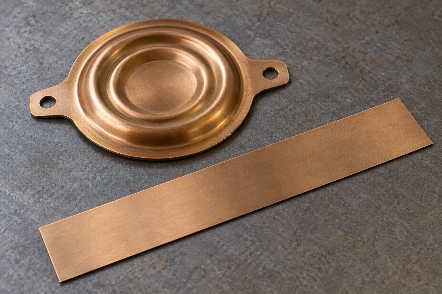
For C52100 formed parts, separate tab dimensions from any deflection, force or leak test.
| Your decision | What to define |
|---|---|
| Your fit | Corrugation geometry, supported mounting tabs and working deflection. |
| Your route | Stock condition, support and finishing sequence. |
| Your approval | Final geometry, surface and receiving evidence. |
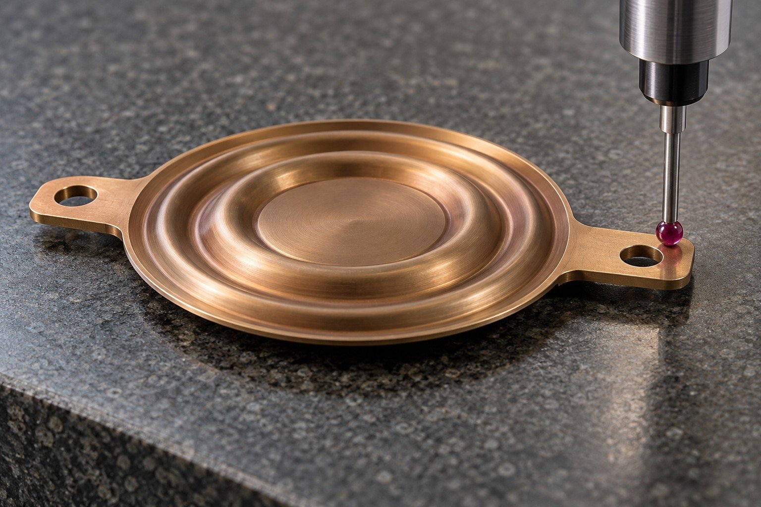
For C52100 chemical composition acceptance, state the product standard and supplier certificate scope. A narrow strip range is not the same acceptance range as a drawn-product reference.
Show the working feature and allowed edge condition.
Agree stock, support and final surface.
Inspect the actual finished state.
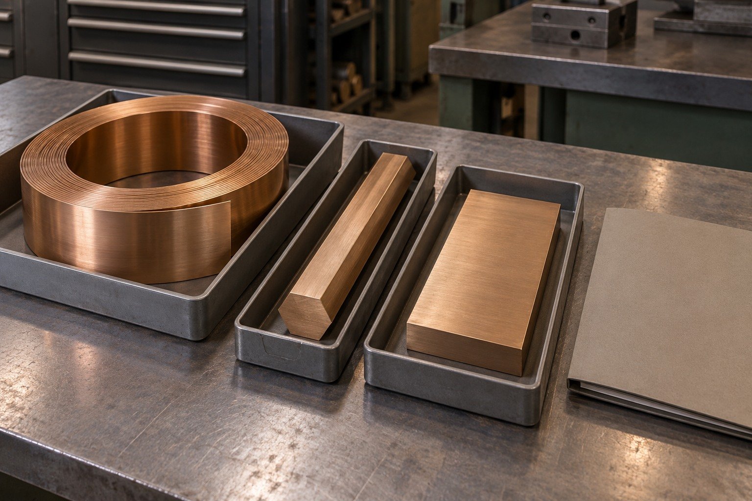
Show open slot, bore and shoulder relationships. Agree internal-edge access and cleaning without damaging the finished contact land.
Show the working feature and allowed edge condition.
Agree stock, support and final surface.
Inspect the actual finished state.
Specify rolling direction, thickness, supplied temper and final bend. C52100 hardness depends on product and condition; a single alloy-wide hardness is not a drawing requirement.
Show the working feature and allowed edge condition.
Agree stock, support and final surface.
Inspect the actual finished state.
Mark allowed burrs, edge breaks and contact tips. A dimensional report alone does not confirm an acceptable working edge.
Show the working feature and allowed edge condition.
Agree stock, support and final surface.
Inspect the actual finished state.

Show contact surfaces, coating limits and accepted texture. Review any plating thickness and its effect on final mating geometry separately.
Show the working feature and allowed edge condition.
Agree stock, support and final surface.
Inspect the actual finished state.

Define support and restraint for the actual thin part. Agree free and installed states, datums and any separately specified force or deflection method.
Show the working feature and allowed edge condition.
Agree stock, support and final surface.
Inspect the actual finished state.

For your C52100 machining services inquiry, distinguish supported cut features from the thin working section. Your review confirms whether forming, stamping and secondary machining can meet the same controlled drawing.

Control the collar shoulder and contact bore from the agreed datum and stock condition.
Review the Process →
Keep the connector slot accessible and the eccentric mounting base fully supported.
Review the Process →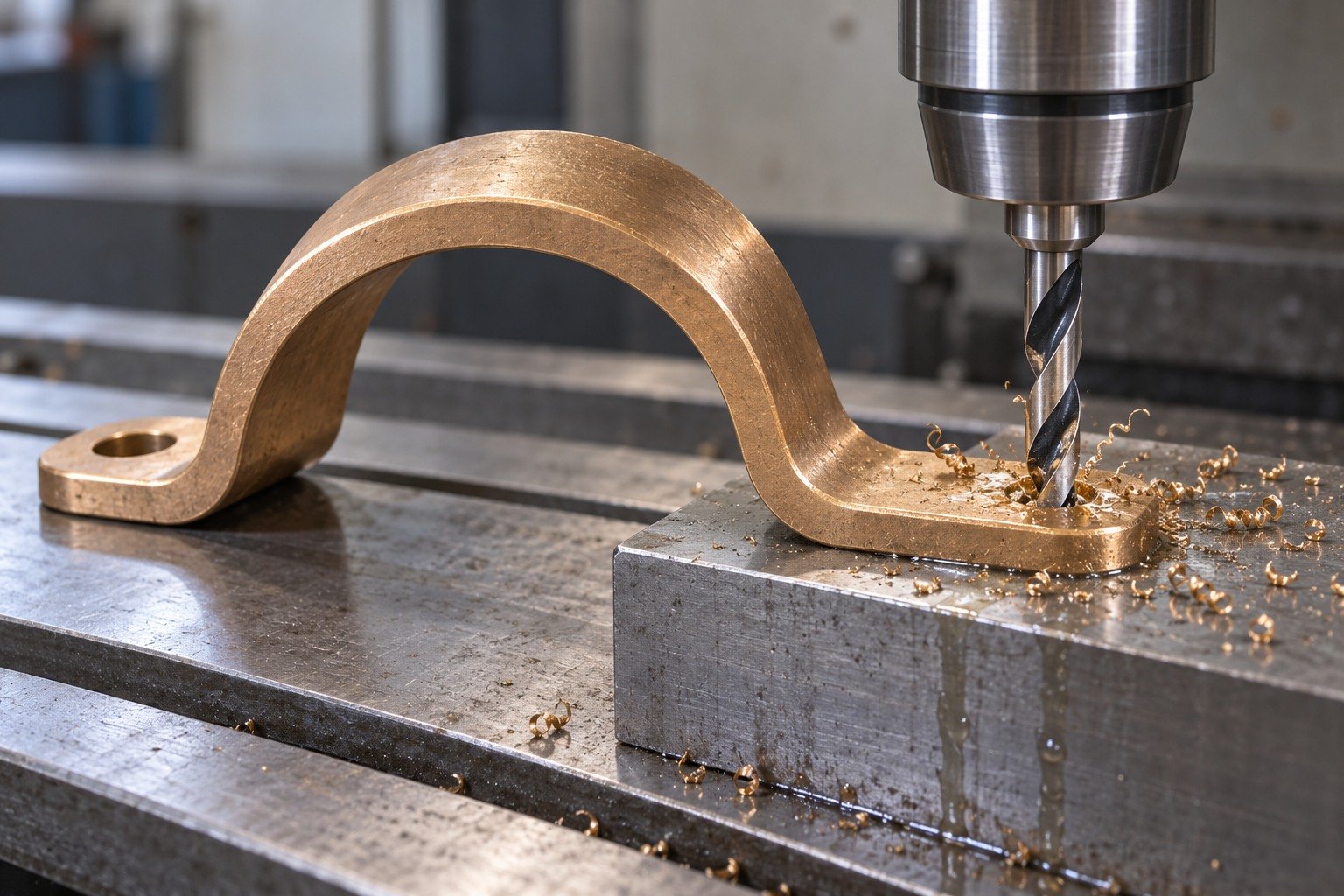
Define wing-hole backing and allowed exit edges without distorting the clip.
Review the Process →
For C52100 stamping services, agree the flat blank, corrugation tooling and final diaphragm state before a production route is quoted.
Review the Process →Grade, product standard and supplied state.
Supported dimensions and accepted edges.
Final function requirements and receiving records.
For your custom C52100 parts, define C52100 material certification by the exact product standard, supplied condition, traceable lot and required document scope. Do not substitute a generic datasheet for a lot record.
Sampling and evidence scope are agreed with your quote.
Quality Assurance →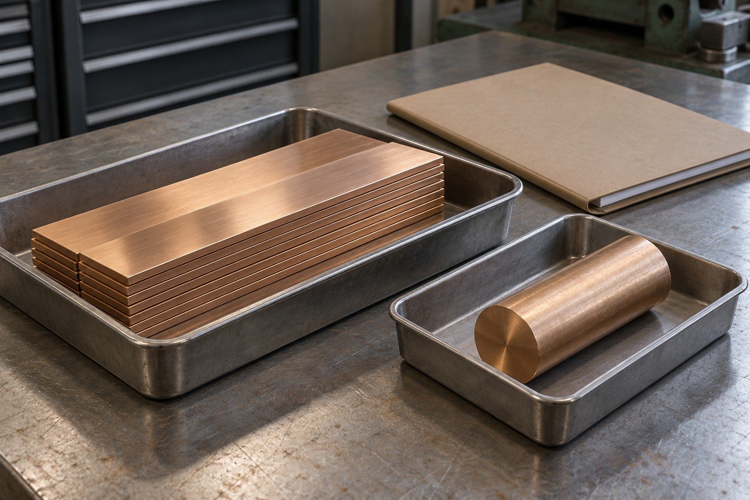
Review mounting datums, supported dimensions and contact edges on a complete first sample. Any contact-force test needs agreed points and restraint.
Sampling and evidence scope are agreed with your quote.
Quality Assurance →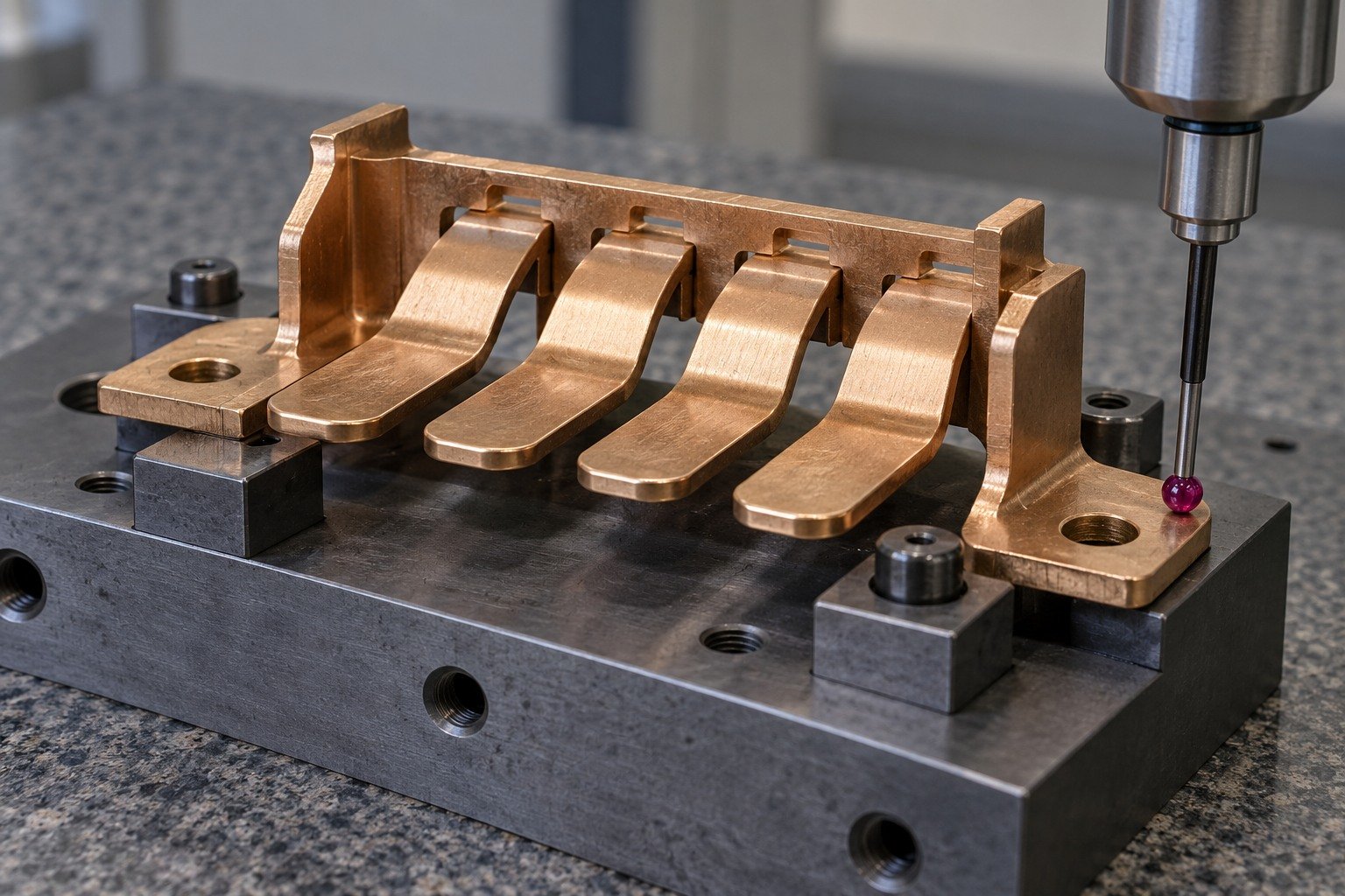
Accept the actual final state after agreed cutting, forming and finishing. Keep dimensional inspection distinct from functional qualification.
Sampling and evidence scope are agreed with your quote.
Quality Assurance →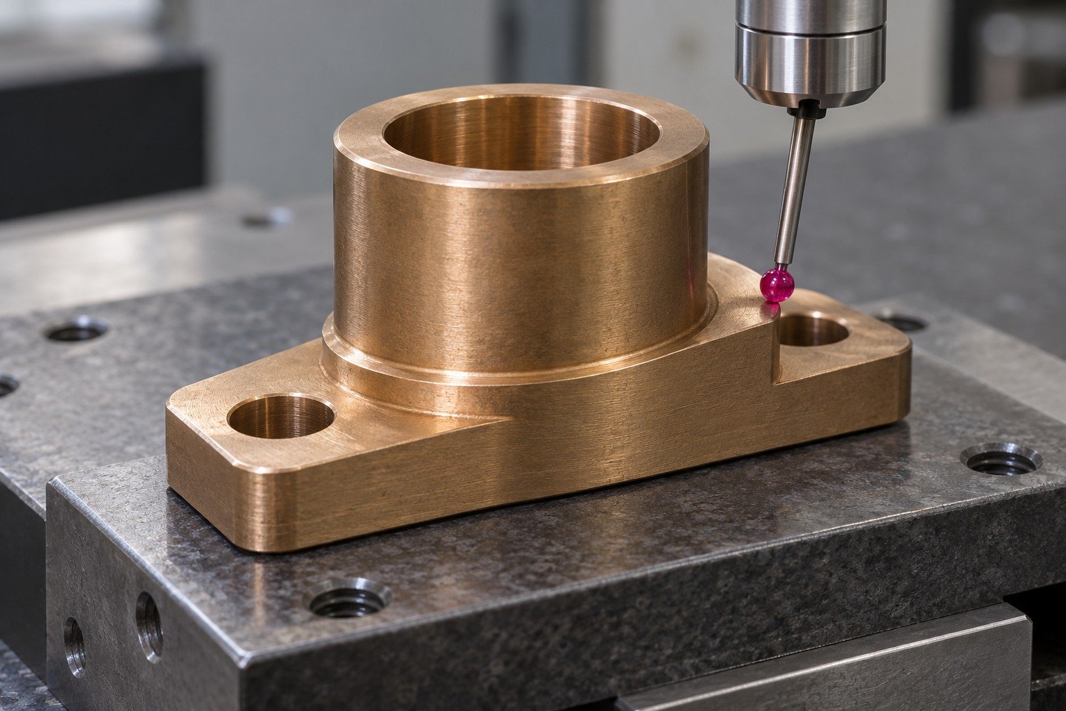
Your C52100 machined parts manufacturer review should agree lot records, part separation, contact protection and receiving-document scope.
Sampling and evidence scope are agreed with your quote.
Quality Assurance →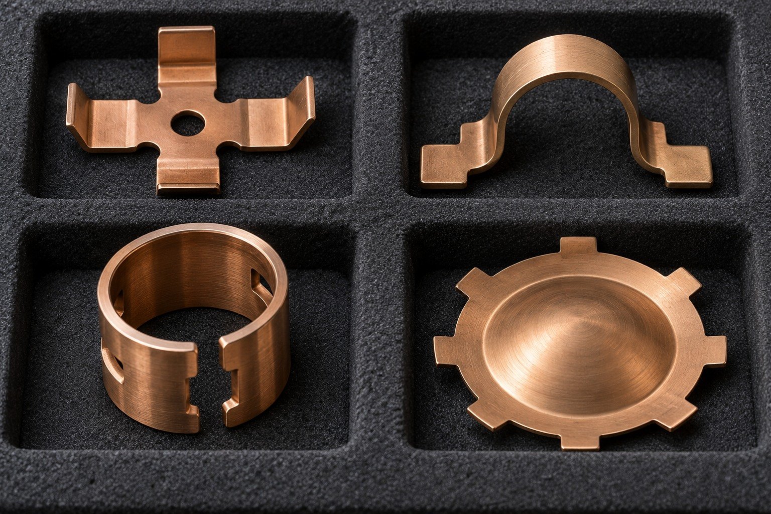
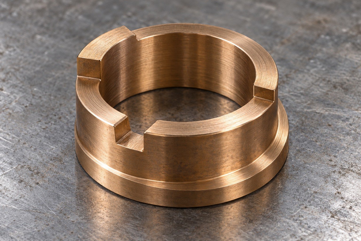


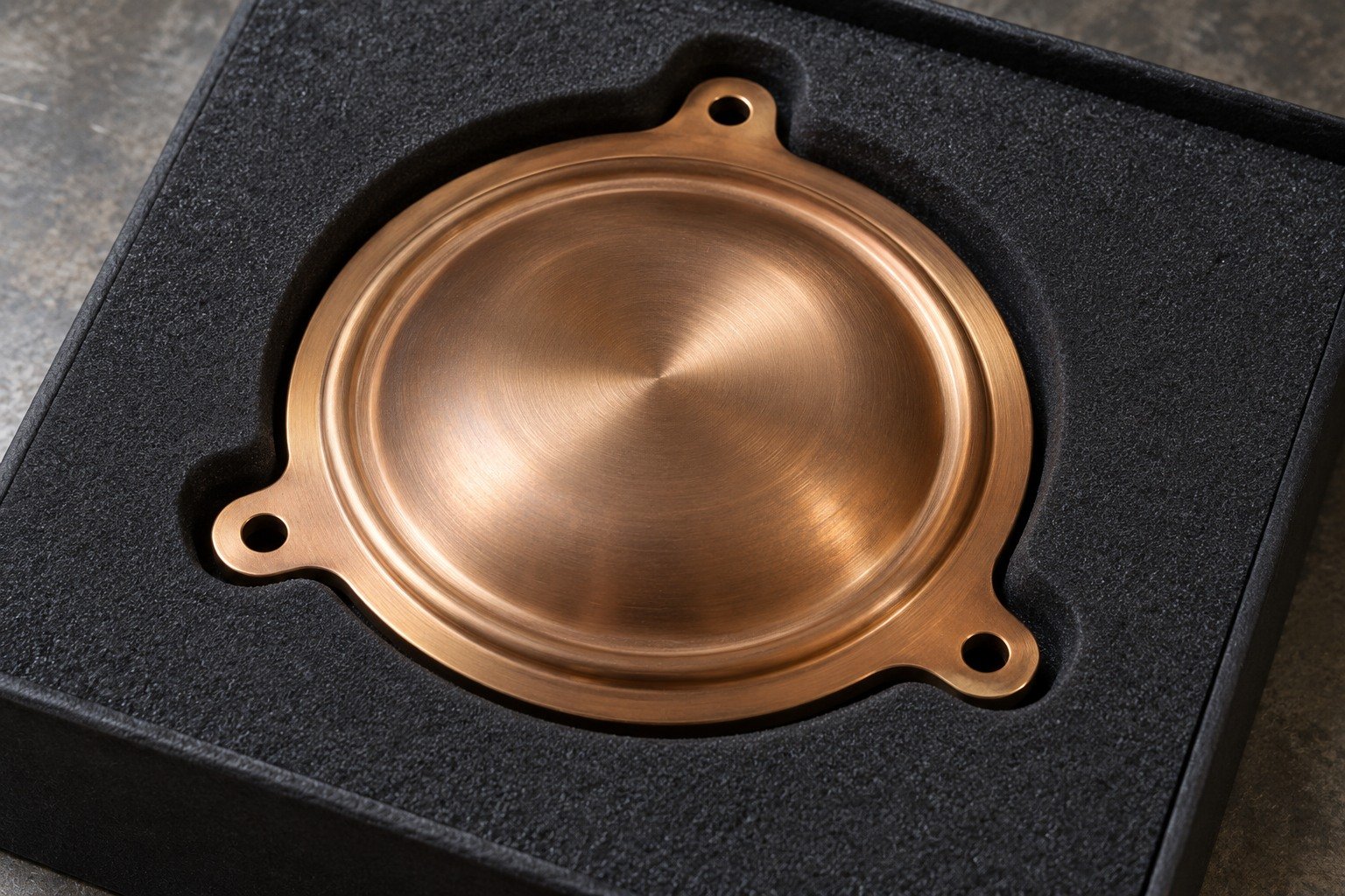
Illustrative concepts. Agree contact texture, edge acceptance, cleaning and handling protection; a photograph does not specify a finish system.
Surface Finishing →| Your check | What to approve |
|---|---|
| Tin and product limits | Use selected C52100 drawn-product Sn 7–9%; European strip specifications can differ. |
| Temper and bend | Specify the actual strip state, rolling direction and final geometry. |
| Working function | State movement, mating contact and any force or electrical test. |
| European name | CuSn8 / CW453K is a qualified C52100 comparison; approve full requirements. |
A cutting index or a higher tin content does not approve an alloy substitution.
Bronze Alloy Overview →
Connect China manufacturing with Dallas-area coordination for drawing review, sample decisions and delivery requirements.
Your C52100 machining quote should use the same product specification, mounting support, functional-test scope and accepted final geometry.
C52100 is a wrought phosphor-bronze designation commonly described by nominal 8% tin. Order the exact product, specification and supplied condition, then define the working geometry.
For C52100 machinability, Concast drawn-product data lists an indicative index of 20. Aurubis PNA 283 strip rates machining as not recommended. Review stock form and actual cut features rather than transferring one assessment to every product.
Provide controlled CAD and drawing, exact grade and product standard, strip or bar dimensions and temper, quantities, working surfaces and material records. Add any force or electrical test with its method and acceptance.
Specify feature limits, supported datums, measurement restraint and final state. Your quotation confirms the reviewed acceptance; thin spring geometry and rigid collar features need different support.
State the ordered product standard, supplied state, lot traceability and certificate type or required content. Material documents do not replace dimensional or functional test evidence.
Eight percent is a nominal alloy description, not an exact analysis for every lot. Selected Concast drawn-product limits are 7–9 wt.% Sn; Aurubis PNA 283 strip uses 7.5–8.5 wt.% with separate other limits.
For C52100 stamping, identify the blank, thickness, forming sequence, tool access and final state. Any secondary cut features need adequate support and accepted edges. Your quote confirms the available route and tooling scope.
Aurubis and Kemper identify this as a comparable C52100 reference. Confirm the complete ordered limits, product form and supplied condition; a short name does not approve automatic replacement.





