Injection Molding
Tooling and molding for your repeat plastic parts.
From prototype to production, coordinated manufacturing solutions for your custom parts.
View All Services →
Precision parts for your tight tolerances and complex geometry.
Tooling and molding for your repeat plastic parts.

Metal casting options for your part and production volume.

Cutting, forming and welding for your fabricated parts.

Custom profiles for your section, length and finish requirements.

Finishes for your appearance, corrosion and wear requirements.

Sub-assemblies and final builds for your production program.

Production tooling built around your process and volume.

Prototype parts to check fit, function and design.
DFM, process planning and production support for your project.
Inspection, documentation, inventory and delivery planning for your program.
Choose air- or liquid-cooling components around your thermal and mechanical requirements.

Manufacturing support for your cold plates, manifolds and cooling assemblies.

Find components for your power electronics, energy, laser and telecom application.

Components for your electronic systems.
Start with your functional and quality requirements.
Build around your operating environment.
From prototype to production, review material performance, manufacturability and cost for your part.
Review grade, temper and finish for your metal parts.
 AluminumStrength, weight and machining›
 Stainless SteelCorrosion and finish requirements›
 Carbon & Alloy SteelDiscuss grade and heat treatment›
 Tool SteelDiscuss tooling and wear needs›
 TitaniumReview grade and part geometry›
 Copper & Brass & BronzeDiscuss conductivity and machining›
Match your polymer to function, process and environment.
 ABSReview enclosure and molding needs›
 Polycarbonate (PC)Discuss clarity and impact needs›
 Nylon (PA)Review moisture and wear conditions›
 POM / AcetalReview fit and sliding features›
 PEEKDiscuss operating conditions›
 PTFEReview friction and chemical exposure›
 ULTEM / PEIDiscuss thermal and electrical needs›
Confirm grade availability and application requirements.
 Silicone / LSRDiscuss flexible component needs›
 TPU / TPEReview flexibility and processing›
 EPDMReview weathering and chemical exposure.›
 NBRReview oil and fuel exposure.›
 FKMReview temperature and chemical exposure.›
 G10 / FR4Review insulation and laminate needs›
 CompositesReview stiffness, weight and laminate.›Customer-Specified MaterialsConfirm your grade and requirements.›Other Specialty MaterialsDiscuss your application and grade.›
Practical guidance for your part geometry and material decisions.
Prepare your process, budget and sourcing questions.
Build your knowledge before production.
Learn who we are and how we operate.
Find our U.S. support team or start a conversation.
YOUR CONTACT FACES. YOUR APPEARANCE. YOUR FINISHED FIT.
For surface finish selection for machined parts, start with the substrate, working environment, mating features and visible surfaces. Agree what is measured and what is judged visually before release.

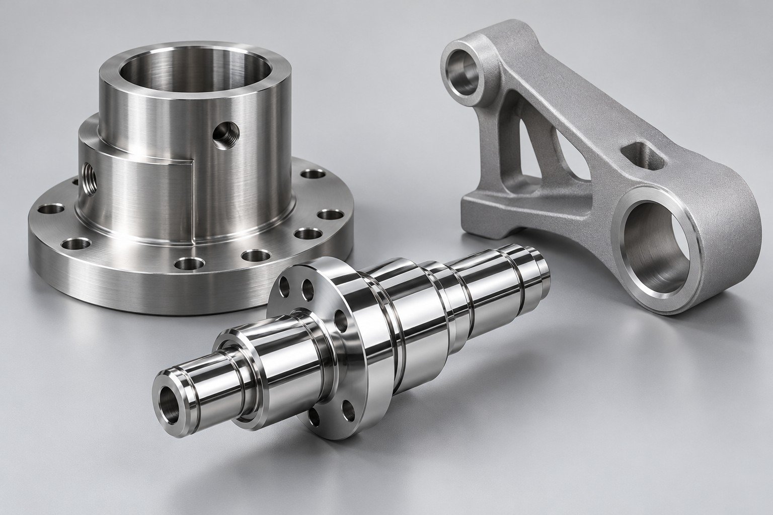
Identify substrate, exposure, cleaning and the applicable test or acceptance specification. A finish name alone does not establish service life.
Mark mating fits, threads, electrical contacts and sealing faces that need protection or post-finish inspection.
Define visible zones, color or texture references, permissible marks and an agreed viewing condition.
For anodizing dimensional allowance, distinguish the specified coating thickness from the change in the outside dimension. Do not apply the deposited-layer example below to anodizing without process-specific review.
Assume a uniform deposited layer t on each of two opposing flat faces. Gap reduction = 2t. Zero baseline0–30μm.
Assumed geometry only. These are not prescribed coating thicknesses, measured results or an anodizing growth model. Real growth, distribution and substrate removal depend on the specified process.
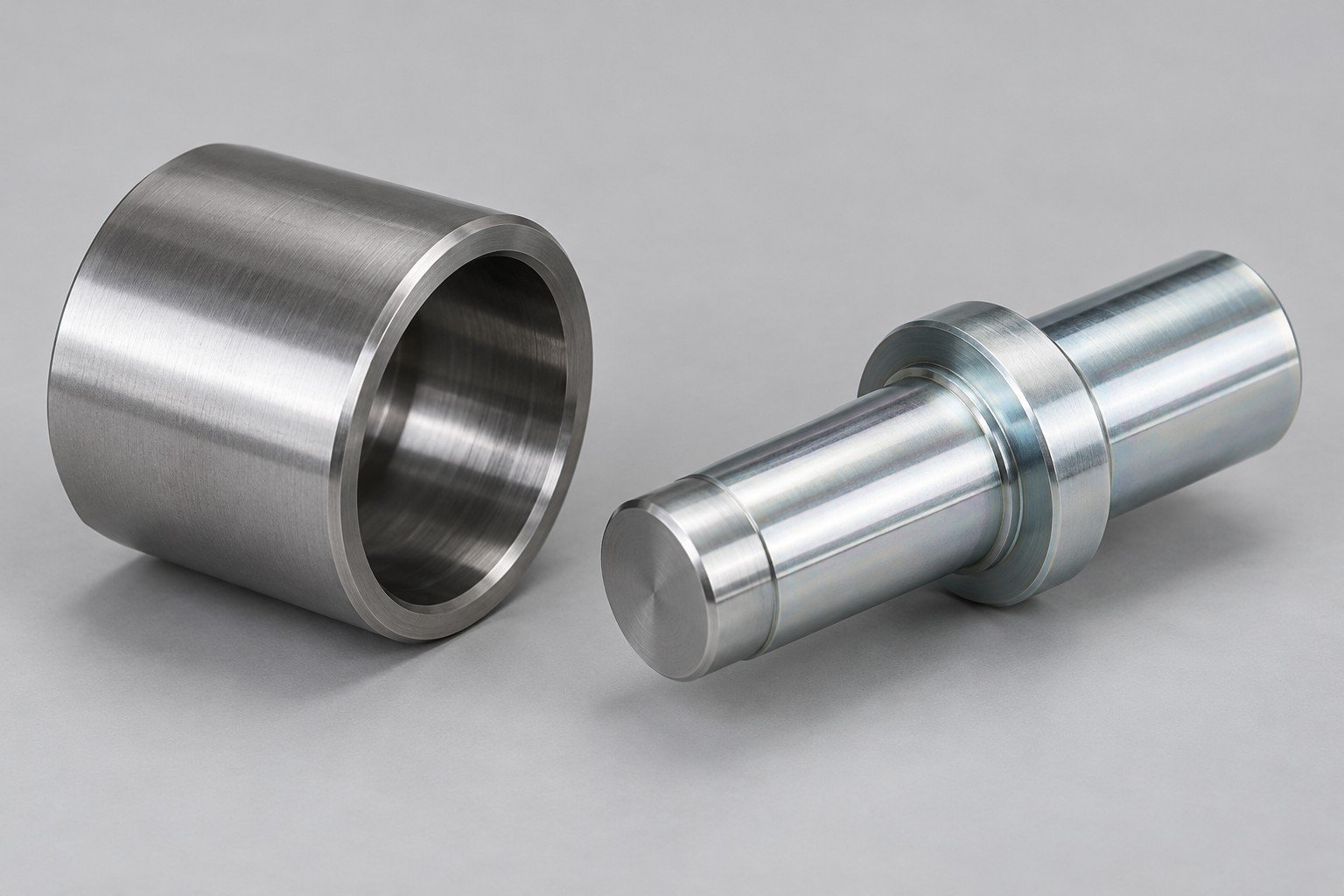
A matching appearance does not prove a matching fit. Background on finish-related dimensions: Protocase finish tolerance guidance →. Its supplier-specific values are not LK MFG specifications.
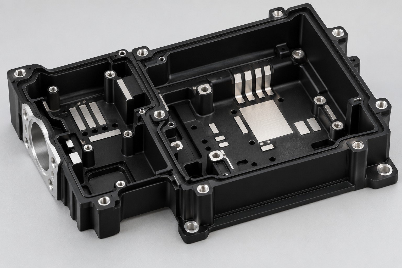
Mark masked zones and the required condition after finishing. Review practical boundaries and inspection access rather than relying on a color rendering.
Identify contact pads, bonding areas and the required surface condition.
Show which bores, seats or threads require protection or a controlled finished dimension.
Agree mask boundary locations, handling marks and appearance expectations near transitions.
Background: Protolabs finishing and masking overview →. The photograph is an illustrative concept,not evidence of a measured coating.
Surface roughness requirements on drawings should identify the controlled surface,parameter,units and applicable measurement conditions.
Cosmetic surface acceptance criteria should identify visible zones,reference samples,lighting,viewing condition and permissible marks.
Agree which records support dimensional,coating and appearance acceptance. A glossy photograph is not a roughness report.
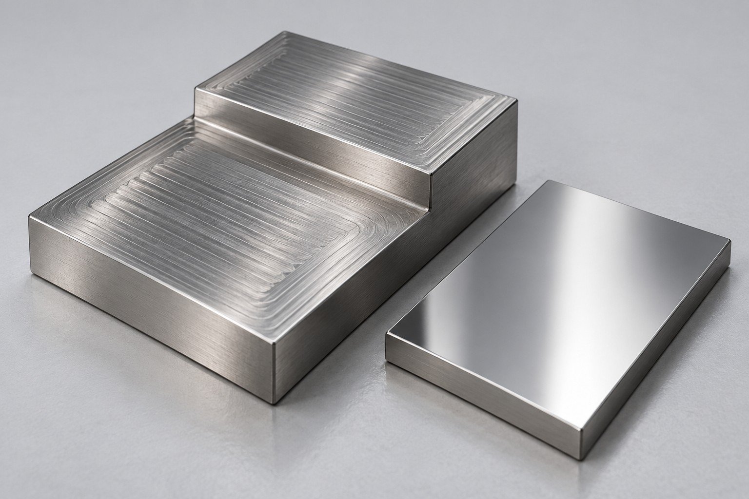
No numerical roughness value is assigned to either concept surface.
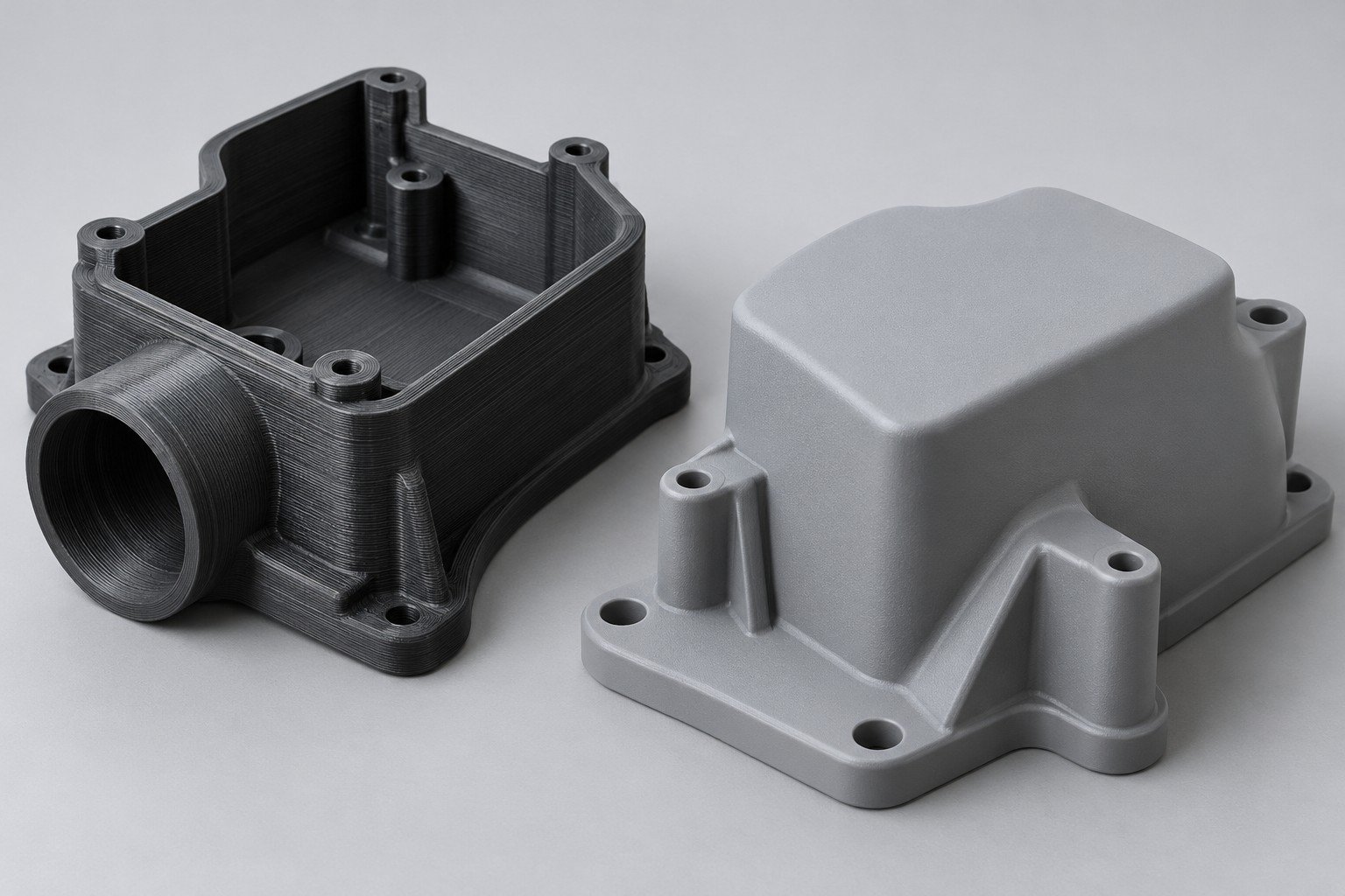
A 3D printed surface finish depends on build process,material,orientation,support contacts and the selected post-processing route. Agree how finishing affects details and mating features.
Identify surfaces where texture or support removal matters to function or appearance.
Review cleaning,sanding,blasting,painting or another proposed route for your actual material. Availability is confirmed by project.
Define any critical surfaces that require measurement after finishing rather than judging fit from appearance.
The two components are different illustrative concepts,not a before-and-after test. Reference topics: Xometry process-specific finish options →.

State the required acceptance condition explicitly. Identify finished fits,threads,masked areas and any dimensions that must also be controlled before treatment.
Do not assume they are identical. Review the alloy,pretreatment,anodizing specification and dimensional change with the finishing supplier.
No. Specify the surface parameter and measurement conditions. Judge cosmetic requirements against a separately agreed visual standard.
No. Confirm substrate compatibility,process availability,functional requirements and final acceptance before ordering.
Review finishing services → · Connect finish to inspection → · Review part design →