Injection Molding
Tooling and molding for your repeat plastic parts.
From prototype to production, coordinated manufacturing solutions for your custom parts.
View All Services →
Precision parts for your tight tolerances and complex geometry.
Tooling and molding for your repeat plastic parts.

Metal casting options for your part and production volume.

Cutting, forming and welding for your fabricated parts.

Custom profiles for your section, length and finish requirements.

Finishes for your appearance, corrosion and wear requirements.

Sub-assemblies and final builds for your production program.

Production tooling built around your process and volume.

Prototype parts to check fit, function and design.
DFM, process planning and production support for your project.
Inspection, documentation, inventory and delivery planning for your program.
Choose air- or liquid-cooling components around your thermal and mechanical requirements.

Manufacturing support for your cold plates, manifolds and cooling assemblies.

Find components for your power electronics, energy, laser and telecom application.

Components for your electronic systems.
Start with your functional and quality requirements.
Build around your operating environment.
From prototype to production, review material performance, manufacturability and cost for your part.
Review grade, temper and finish for your metal parts.
 AluminumStrength, weight and machining›
 Stainless SteelCorrosion and finish requirements›
 Carbon & Alloy SteelDiscuss grade and heat treatment›
 Tool SteelDiscuss tooling and wear needs›
 TitaniumReview grade and part geometry›
 Copper & Brass & BronzeDiscuss conductivity and machining›
Match your polymer to function, process and environment.
 ABSReview enclosure and molding needs›
 Polycarbonate (PC)Discuss clarity and impact needs›
 Nylon (PA)Review moisture and wear conditions›
 POM / AcetalReview fit and sliding features›
 PEEKDiscuss operating conditions›
 PTFEReview friction and chemical exposure›
 ULTEM / PEIDiscuss thermal and electrical needs›
Confirm grade availability and application requirements.
 Silicone / LSRDiscuss flexible component needs›
 TPU / TPEReview flexibility and processing›
 EPDMReview weathering and chemical exposure.›
 NBRReview oil and fuel exposure.›
 FKMReview temperature and chemical exposure.›
 G10 / FR4Review insulation and laminate needs›
 CompositesReview stiffness, weight and laminate.›Customer-Specified MaterialsConfirm your grade and requirements.›Other Specialty MaterialsDiscuss your application and grade.›
Practical guidance for your part geometry and material decisions.
Prepare your process, budget and sourcing questions.
Build your knowledge before production.
Learn who we are and how we operate.
Find our U.S. support team or start a conversation.

YOUR MATING PARTS. YOUR DATUMS. YOUR RELEASED REVISION.
For your industrial equipment parts manufacturer review, connect the component drawing to its installed function. Share mating interfaces, material condition and sample acceptance before agreeing the manufacturing route.
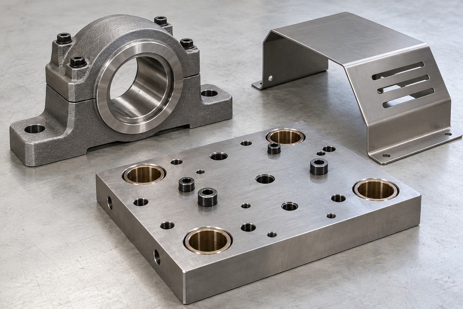
Identify bearing seats, mounting faces, bores and fastener access against the mating assembly.
Review locating features, support surfaces, replaceable inserts and inspection access.
For custom machine guards fabrication, share the released enclosure drawing, mounting details and required machine-owner approval.
Component manufacture does not establish machine safety compliance or approval of an installed guard.
For industrial replacement parts machining, identify which features are worn, repaired or modified. A sample alone cannot define the original material, intended fit or allowable variation.
Share the equipment model, part identity, installed position and any available controlled drawing.
Provide mating components and mark wear, damage, repairs and known fit problems.
Approve the replacement drawing, material condition and defined checks before repeat manufacture.
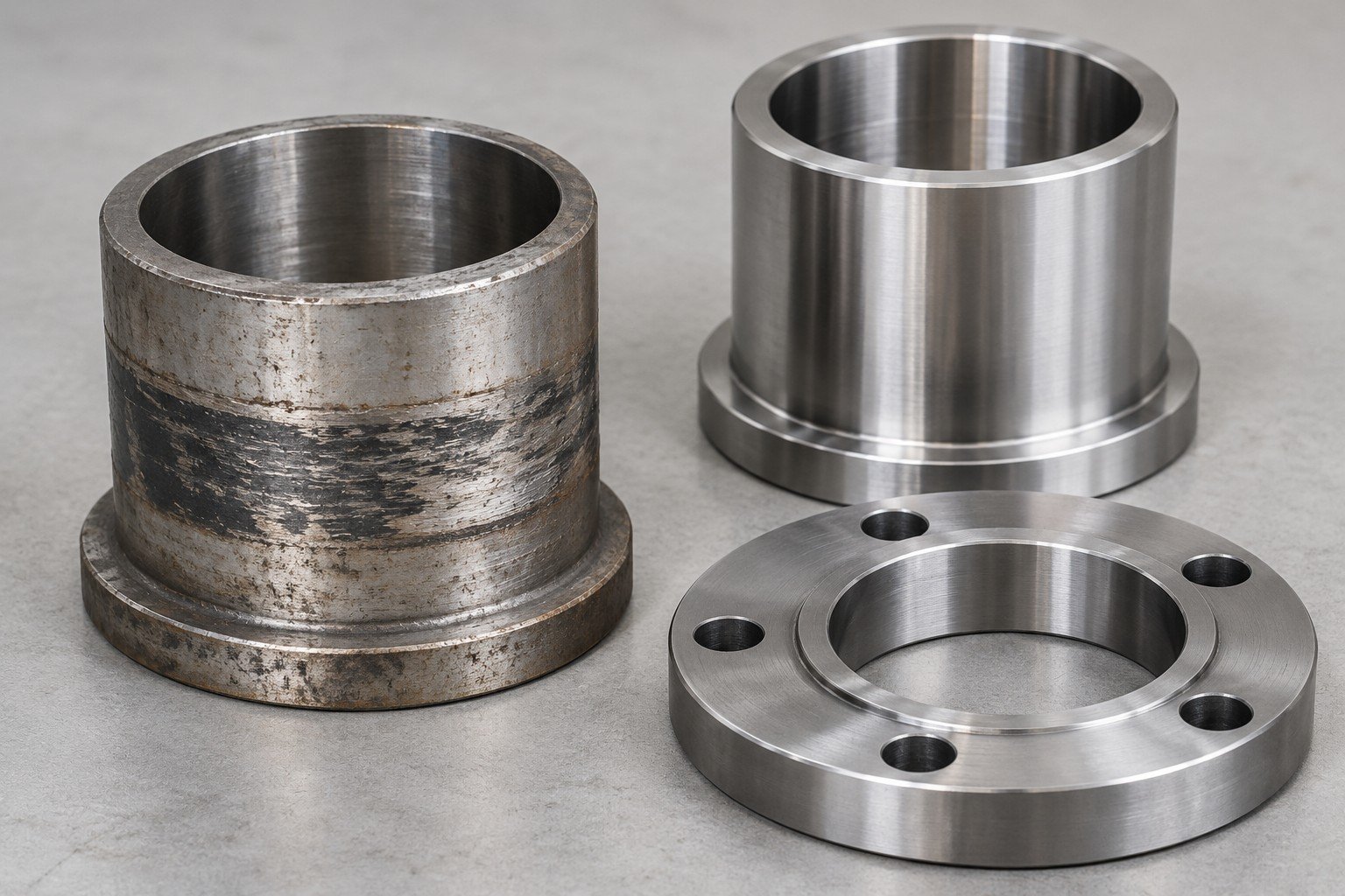
Confirm your authority to reproduce the component and any equipment-owner restrictions.
For industrial equipment fixture machining, show which surfaces establish the part position and which fasteners apply holding force.

For a suitable prismatic workpiece, this reference arrangement distributes locating contacts across three faces. Review your actual geometry, forces and loading method before applying it.
Common plane-locating arrangement; zero baseline 0–3 contacts.
3 + 2 + 1 = 6 locating contacts. Contact count is not a repeatability, tolerance, clamping-force or safety rating.
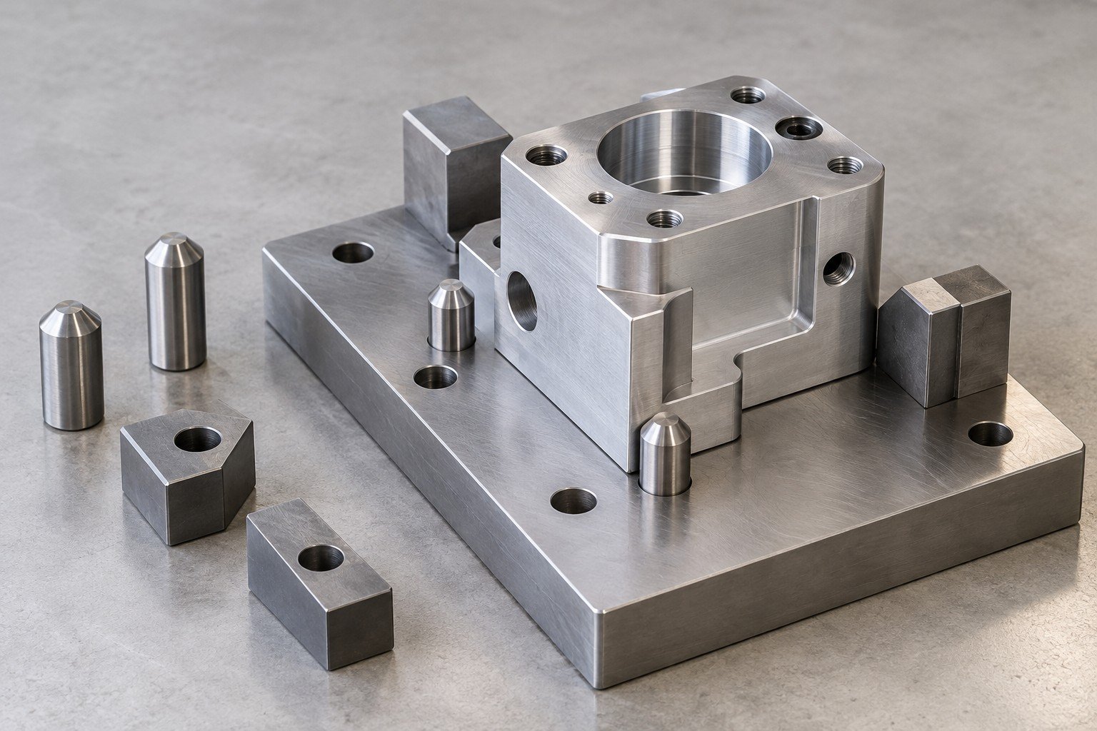
Support locations, workpiece rigidity, access for loading and inspection, cutting-force direction, holding-force review and chip clearance all require your specific part.
| Reference role | Contact count | Review on your part |
|---|---|---|
| Primary face | 3 | Use separated, non-collinear support locations appropriate to the surface and load. |
| Secondary face | 2 | Review side location without unnecessary redundant constraint. |
| Tertiary face | 1 | Review the remaining end location and loading access. |
Locators establish the reference; holding/clamping must be reviewed separately. Cylindrical or irregular workpieces may need a different arrangement. Illustrative planning comparison, not an approved fixture design.
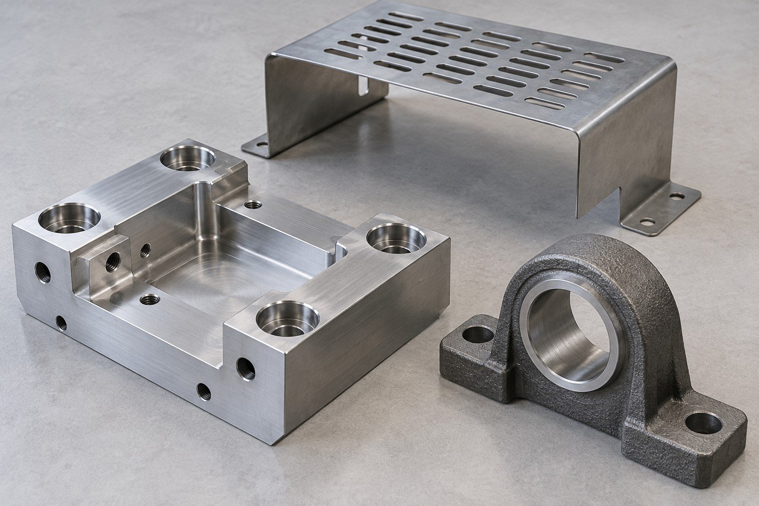
Tie critical dimensions to locating and mating function before choosing the process and final finishing.
| Your component | Route to review | Before your approval |
|---|---|---|
| Bores, locating shoulders and mounting faces | CNC machining | Datums, fit, tool access and final-condition inspection |
| Formed covers and machine guards | Sheet-metal fabrication | Bends, edges, hardware and machine-owner safety review |
| Repeat complex housing geometry | Casting plus machining where appropriate | Material, draft, tooling and critical machined interfaces |
| Multi-part supports and tooling groups | Mechanical assembly | Component revisions, fastening, alignment and sample scope |
Tooling investment, economical quantity and delivery depend on the drawing and order scope. No universal break-even quantity or delivery promise is implied.
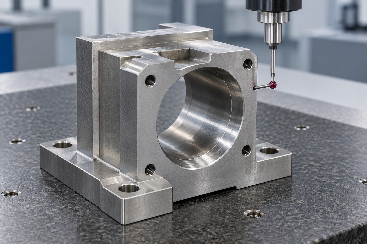
When reviewing wear resistant industrial machine components, specify the mating material, contact conditions, lubrication and required final hardness or treatment where applicable. Material name alone does not establish service life.
Confirm the released revision and agreed substitutions.
Define heat treatment, coating and any post-treatment machining.
Review the selected bores, datum faces and mounting interfaces.
Agree dimensions, sampling and required material/process evidence.
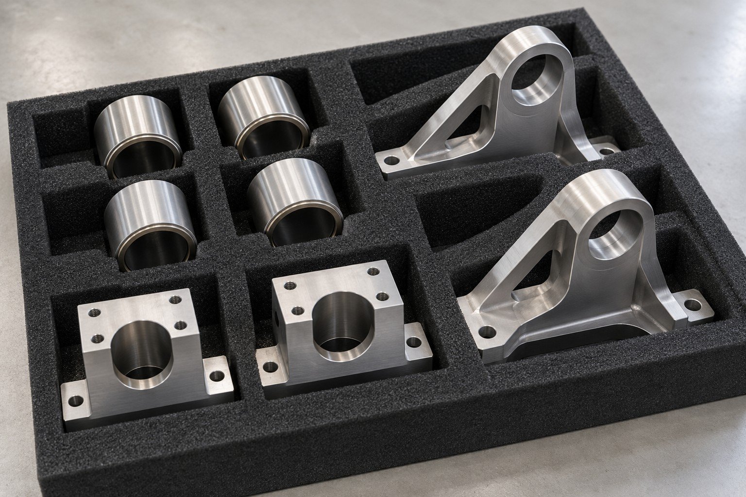
Identify the part, mating assembly and drawing revision.
Review material, access and manufacturing sequence.
Check the defined fit and selected interfaces.
Record accepted features, treatment and evidence.
Confirm repeat scope, packing and delivery requirements.
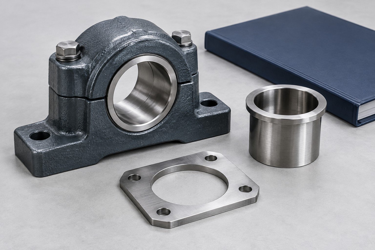
Share the sample condition, available drawings, mating parts and intended function. Agree a controlled replacement drawing and acceptance requirements; do not assume worn dimensions are the original design.
No. It describes reference contacts for suitable geometry. Actual location, stiffness, holding forces, manufacturing variation and inspection must be reviewed for your workpiece.
Identify the contact pair, load, motion, environment, lubrication and required treatment or hardness. Agree the evidence and service-validation scope rather than relying on a generic material label.
Manufacturing scope and component inspection are separate from machine risk assessment and installed guarding approval. The machine owner or designated responsible organization must define that approval.
Connect bores, datum faces and tool access to the route. Explore machining →
Review bends, hardware and assembly seams. Explore fabrication →
Agree the dimensions and records your team needs. Explore inspection →