

Injection Molding
Tooling and molding for your repeat plastic parts.
From prototype to production, coordinated manufacturing solutions for your custom parts.
View All Services →
Precision parts for your tight tolerances and complex geometry.
Tooling and molding for your repeat plastic parts.

Metal casting options for your part and production volume.

Cutting, forming and welding for your fabricated parts.

Custom profiles for your section, length and finish requirements.

Finishes for your appearance, corrosion and wear requirements.

Sub-assemblies and final builds for your production program.

Production tooling built around your process and volume.

Prototype parts to check fit, function and design.
DFM, process planning and production support for your project.
Inspection, documentation, inventory and delivery planning for your program.
Choose air- or liquid-cooling components around your thermal and mechanical requirements.

Manufacturing support for your cold plates, manifolds and cooling assemblies.

Find components for your power electronics, energy, laser and telecom application.

Components for your electronic systems.
Start with your functional and quality requirements.
Build around your operating environment.
From prototype to production, review material performance, manufacturability and cost for your part.
Review grade, temper and finish for your metal parts.
 AluminumStrength, weight and machining›
 Stainless SteelCorrosion and finish requirements›
 Carbon & Alloy SteelDiscuss grade and heat treatment›
 Tool SteelDiscuss tooling and wear needs›
 TitaniumReview grade and part geometry›
 Copper & Brass & BronzeDiscuss conductivity and machining›
Match your polymer to function, process and environment.
 ABSReview enclosure and molding needs›
 Polycarbonate (PC)Discuss clarity and impact needs›
 Nylon (PA)Review moisture and wear conditions›
 POM / AcetalReview fit and sliding features›
 PEEKDiscuss operating conditions›
 PTFEReview friction and chemical exposure›
 ULTEM / PEIDiscuss thermal and electrical needs›
Confirm grade availability and application requirements.
 Silicone / LSRDiscuss flexible component needs›
 TPU / TPEReview flexibility and processing›
 EPDMReview weathering and chemical exposure.›
 NBRReview oil and fuel exposure.›
 FKMReview temperature and chemical exposure.›
 G10 / FR4Review insulation and laminate needs›
 CompositesReview stiffness, weight and laminate.›Customer-Specified MaterialsConfirm your grade and requirements.›Other Specialty MaterialsDiscuss your application and grade.›
Practical guidance for your part geometry and material decisions.
Prepare your process, budget and sourcing questions.
Build your knowledge before production.
Learn who we are and how we operate.
Find our U.S. support team or start a conversation.
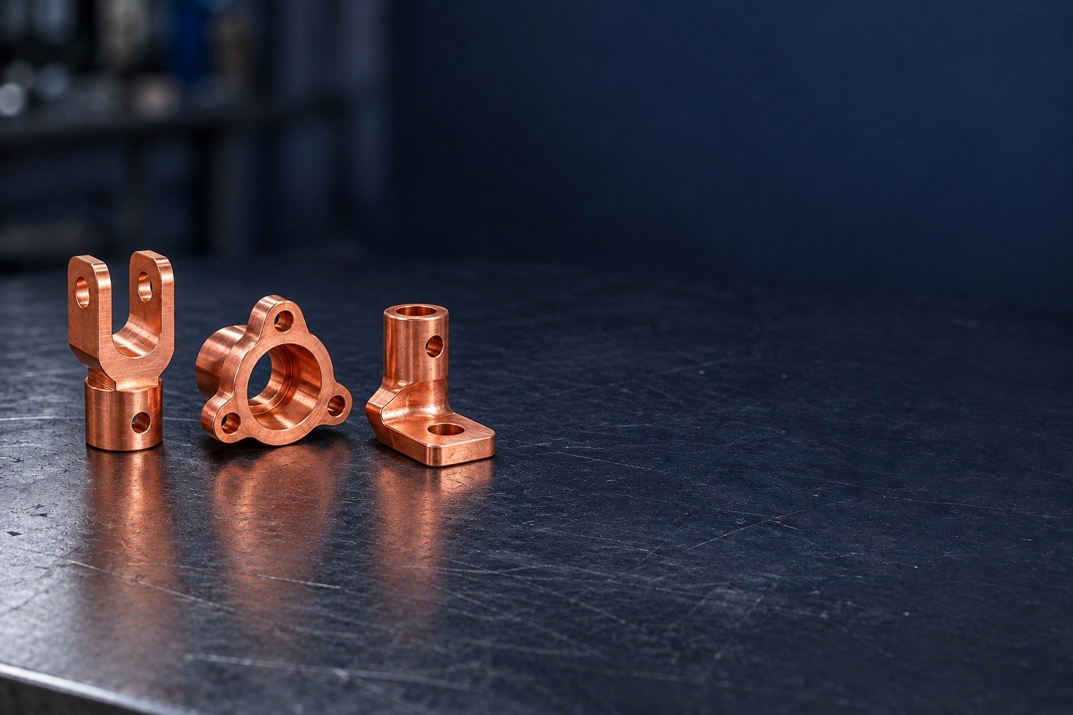
For your C145 tellurium copper machining services inquiry, connect contact geometry, stock temper and accepted edges. Plan your C145 copper CNC machining around the finished assembly.
For C14500 machining and tellurium copper machining, confirm the ordered product form and condition before choosing the route. Tellurium is the selected alloy addition; the combined composition value below is not a pure-copper minimum.
| Identifier | Your purchasing review |
|---|---|
| UNS | C14500 copper / UNS C14500 |
| Common name | Tellurium copper / copper tellurium alloy |
| European reference | CuTeP / CW118C · compare exact specification |
| Material state | Product form, ordered temper and final requirement |
| Acceptance | Controlled standard, lot and receiving records |
| Selected composition | wt.% |
|---|---|
| Cu + Ag + Te + P combined | ≥99.90 · combined value |
| Tellurium (Te) | 0.40–0.70 |
| Phosphorus (P) | 0.004–0.012 |
Wieland Concast selected C14500 reference. The combined minimum includes silver, tellurium and phosphorus; do not add the listed ranges to a supposed 99.90% pure-copper value. Your ordered specification governs.
| Decision | What to separate |
|---|---|
| C145 copper thermal conductivity | Confirm the applicable producer value, temperature and material condition; a finished heat-sink rating requires an assembly assessment. |
| Electrical contact | Define contact pressure, mating area and accepted working surface. |
| Stock and final fit | Identify the actual temper, datums and condition at inspection. |
For your C145 copper machining review, compare the working requirement before changing materials. A machining index is not a cycle-time or cost ratio.
Selected annealed reference at 20°C · % IACS · common scale 0–110
Free-cutting brass = 100 · common scale 0–100
Selected thyssenkrupp alloy brochure: conductivity is for the annealed condition at 20°C; hard temper may differ. Machinability is approximate relative data. Charts are not a lot analysis, finished-part guarantee or substitution approval.
Wieland Concast C14500 ↗ bedra C14500 / CW118C reference ↗ thyssenkrupp alloy brochure ↗
Select a contact, terminal or thermal geometry, then review the operation and evidence your assembly needs.
For your custom C145 copper parts, define the forked contact shoe by its blunt working fingers, rear bridge and mounting pattern. Contact pressure and current-path acceptance belong to your assembly drawing.
| Your decision | What to define |
|---|---|
| Your fit | Finger thickness, spacing, rear datum and counterbored attachment pattern. |
| Your route | Stock condition, support and finishing sequence. |
| Your approval | Final geometry, surface and receiving evidence. |

For C145 copper milling, support the bridge and keep cutter engagement clear of unsupported contact fingers. Agree which faces must remain untouched by clamping.
| Your decision | What to define |
|---|---|
| Your fit | Finger thickness, spacing, rear datum and counterbored attachment pattern. |
| Your route | Stock condition, support and finishing sequence. |
| Your approval | Final geometry, surface and receiving evidence. |
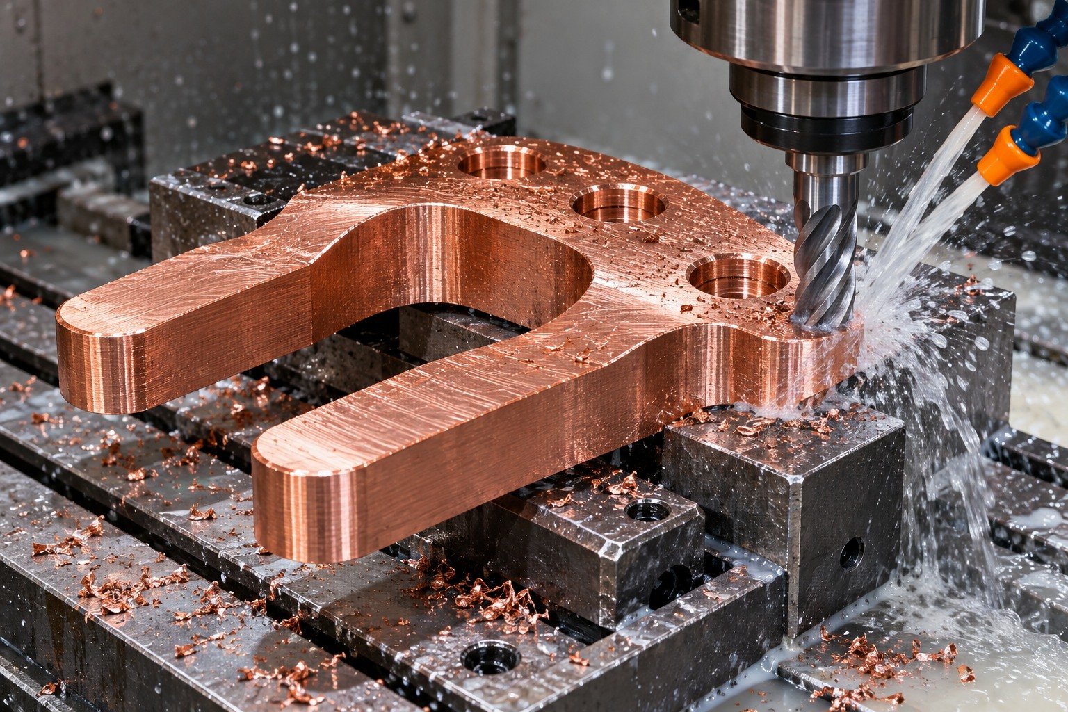
Name the supplied form and temper. Review the relationship between any forming step and the final contact geometry before stock is released.
| Your decision | What to define |
|---|---|
| Your fit | Finger thickness, spacing, rear datum and counterbored attachment pattern. |
| Your route | Stock condition, support and finishing sequence. |
| Your approval | Final geometry, surface and receiving evidence. |
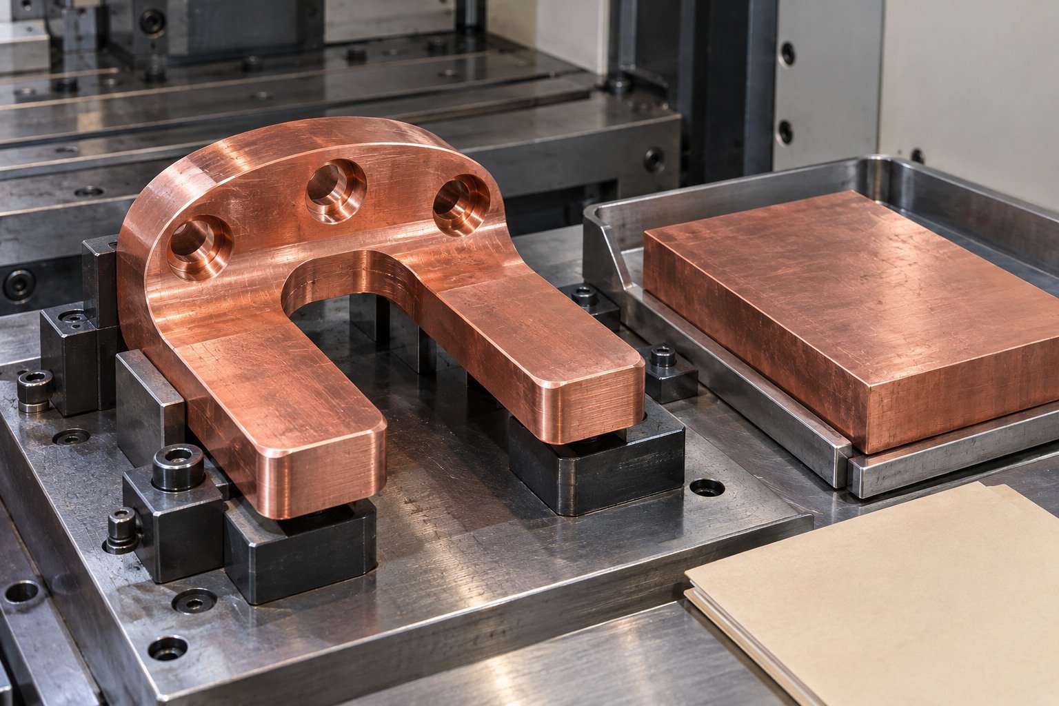
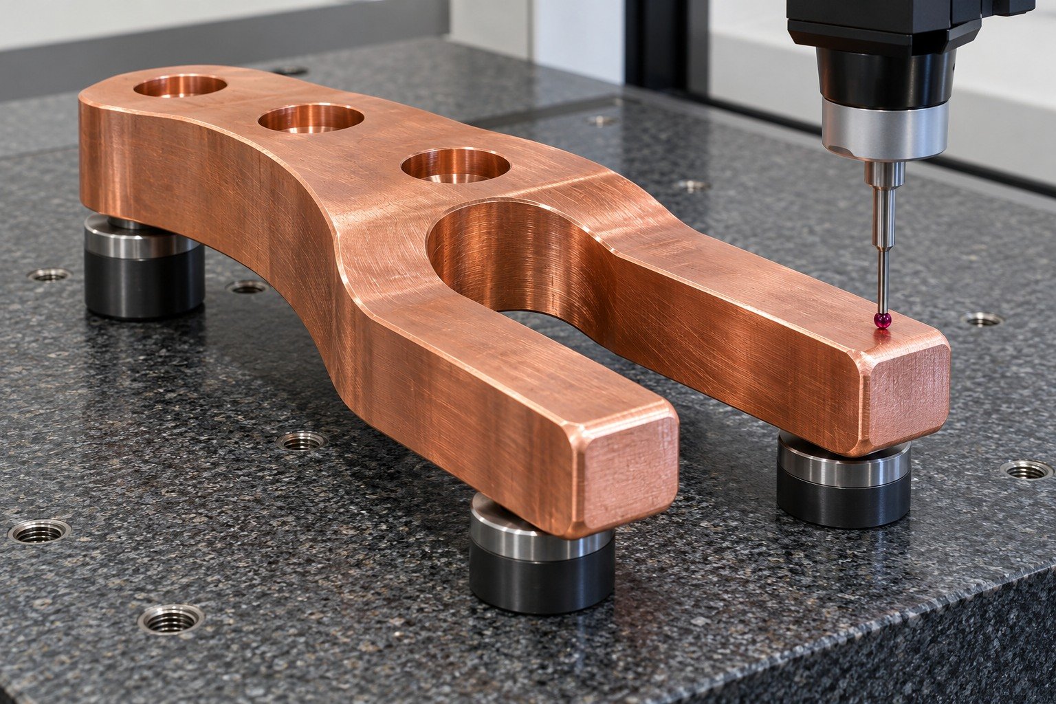
Verify finger spacing, hole location and accepted edges after machining. Keep electrical acceptance distinct from dimensional inspection.
| Your decision | What to define |
|---|---|
| Your fit | Finger thickness, spacing, rear datum and counterbored attachment pattern. |
| Your route | Stock condition, support and finishing sequence. |
| Your approval | Final geometry, surface and receiving evidence. |
Connect a flanged connector sleeve to its actual mating bore, shoulder position and radial access holes. A generic smooth copper finish does not define connector performance.
| Your decision | What to define |
|---|---|
| Your fit | Through-bore fit, flange datums, shoulder length and radial hole access. |
| Your route | Stock condition, support and finishing sequence. |
| Your approval | Final geometry, surface and receiving evidence. |
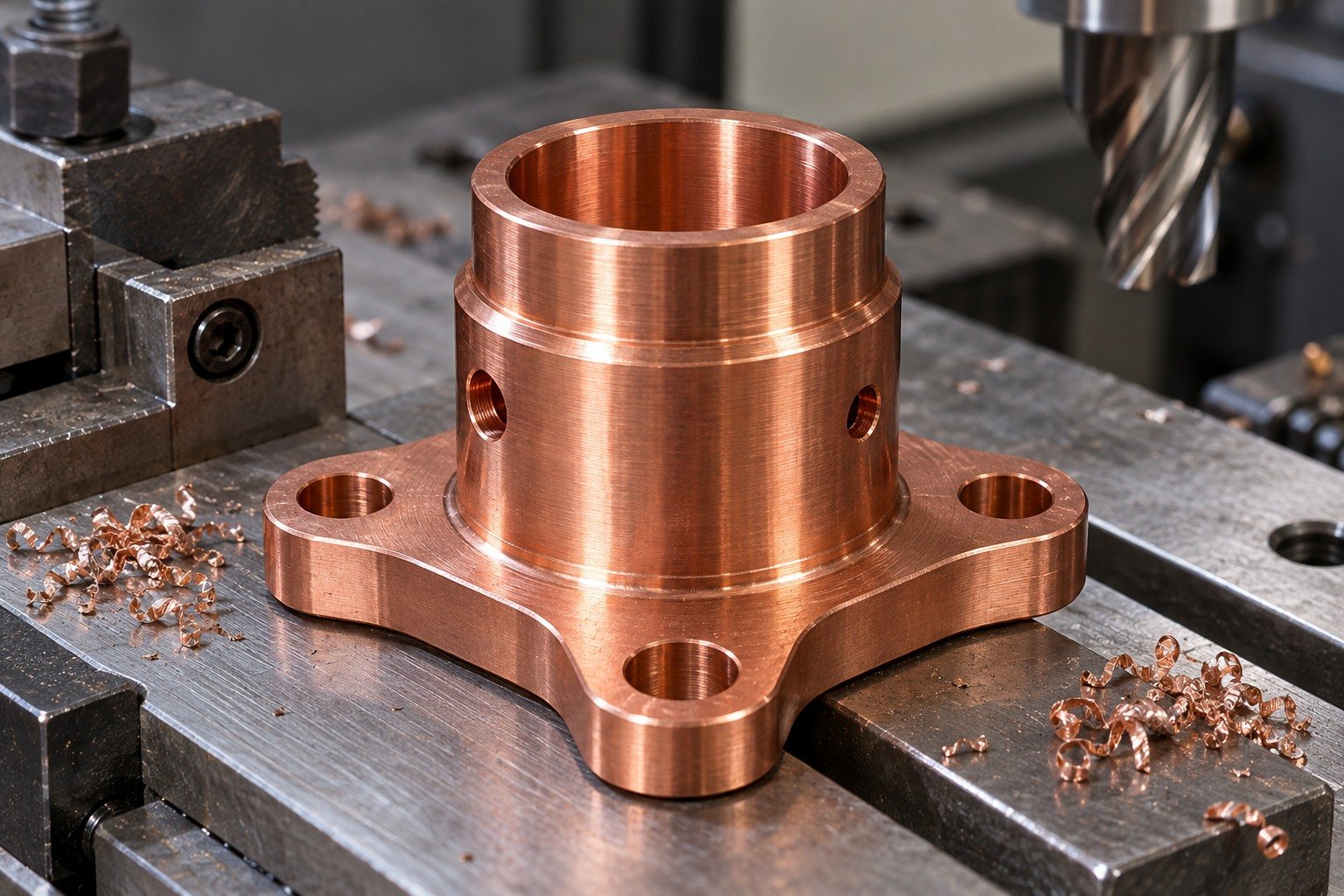
For C145 copper turning, plan firm chuck engagement and short supported shoulders. Review cross-hole entry and the internal edge after drilling.
| Your decision | What to define |
|---|---|
| Your fit | Through-bore fit, flange datums, shoulder length and radial hole access. |
| Your route | Stock condition, support and finishing sequence. |
| Your approval | Final geometry, surface and receiving evidence. |

Keep product form and ordered temper visible in the purchase requirement. A different stock state needs review against the same controlled drawing.
| Your decision | What to define |
|---|---|
| Your fit | Through-bore fit, flange datums, shoulder length and radial hole access. |
| Your route | Stock condition, support and finishing sequence. |
| Your approval | Final geometry, surface and receiving evidence. |
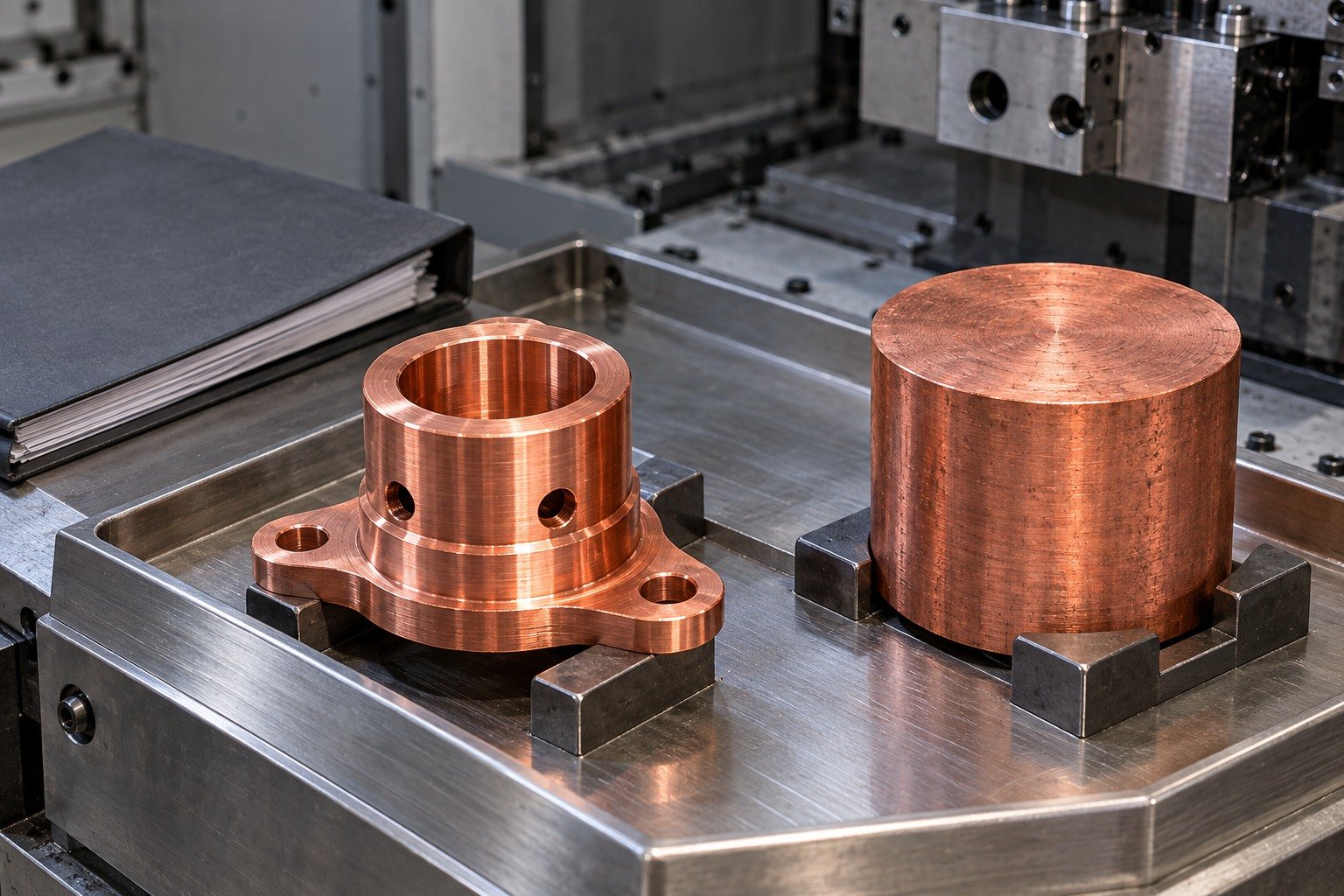
Check bore, shoulder and hole relationships in the agreed final state. Protect the annular working land during handling.
| Your decision | What to define |
|---|---|
| Your fit | Through-bore fit, flange datums, shoulder length and radial hole access. |
| Your route | Stock condition, support and finishing sequence. |
| Your approval | Final geometry, surface and receiving evidence. |
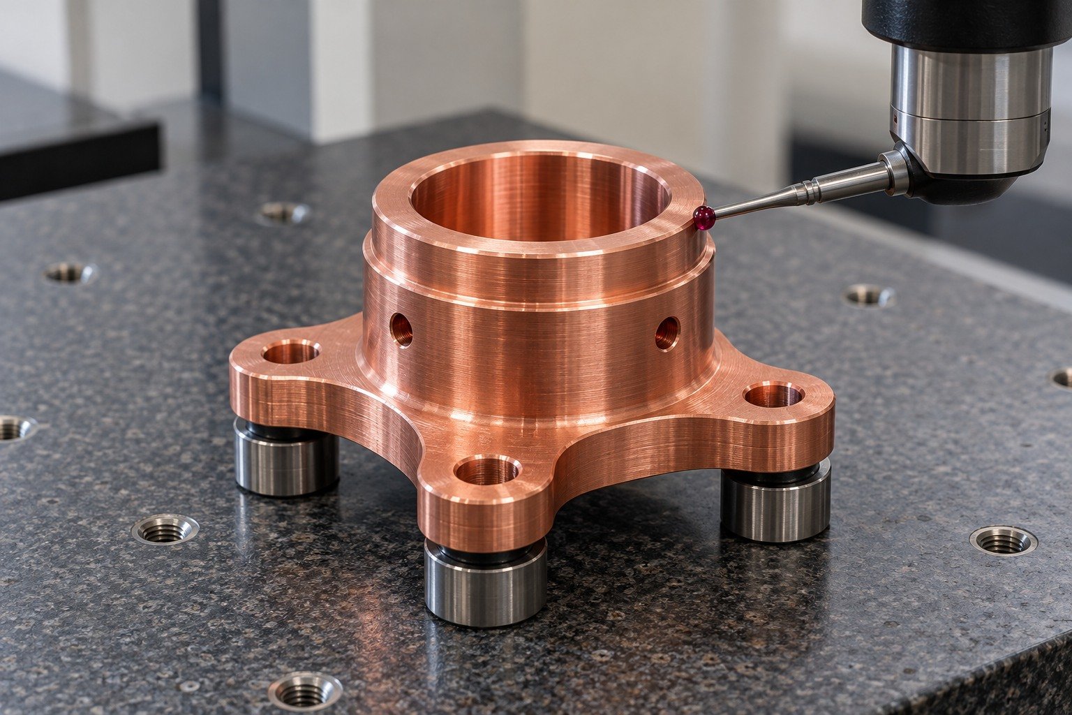
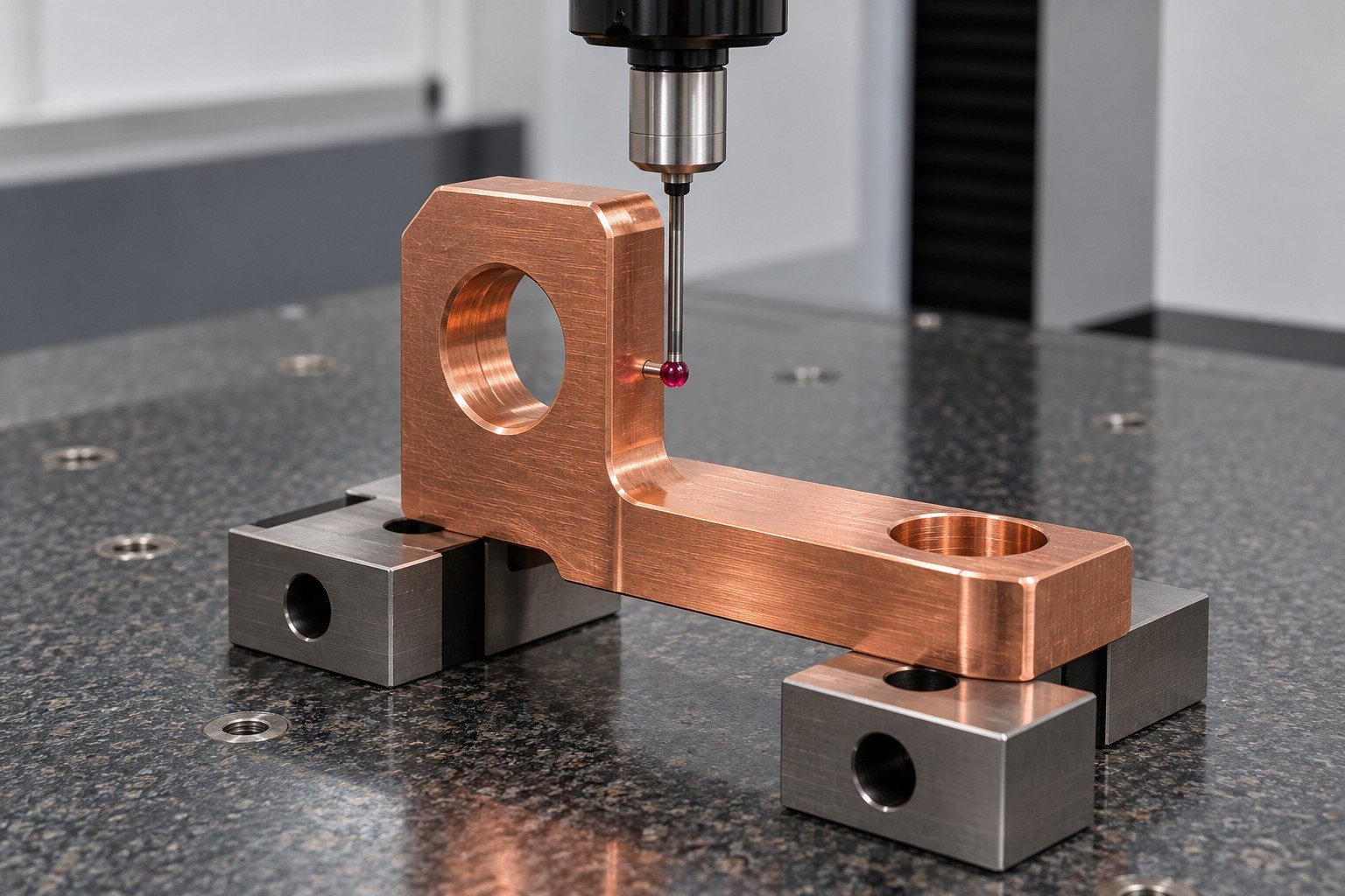
Review a slotted thermal mounting base around its actual mounting ears and contact plane. A material conductivity reference does not establish thermal dissipation in your finished assembly.
| Your decision | What to define |
|---|---|
| Your fit | Mounting-ear datums, slot access, boss geometry and contact-plane requirements. |
| Your route | Stock condition, support and finishing sequence. |
| Your approval | Final geometry, surface and receiving evidence. |
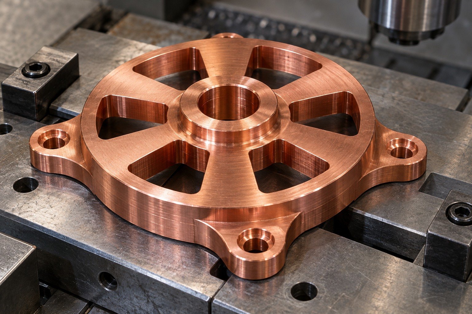
Review tool access around radial slots and support under the base. Keep clamps away from the contact plane and thin exposed slot ends.
| Your decision | What to define |
|---|---|
| Your fit | Mounting-ear datums, slot access, boss geometry and contact-plane requirements. |
| Your route | Stock condition, support and finishing sequence. |
| Your approval | Final geometry, surface and receiving evidence. |
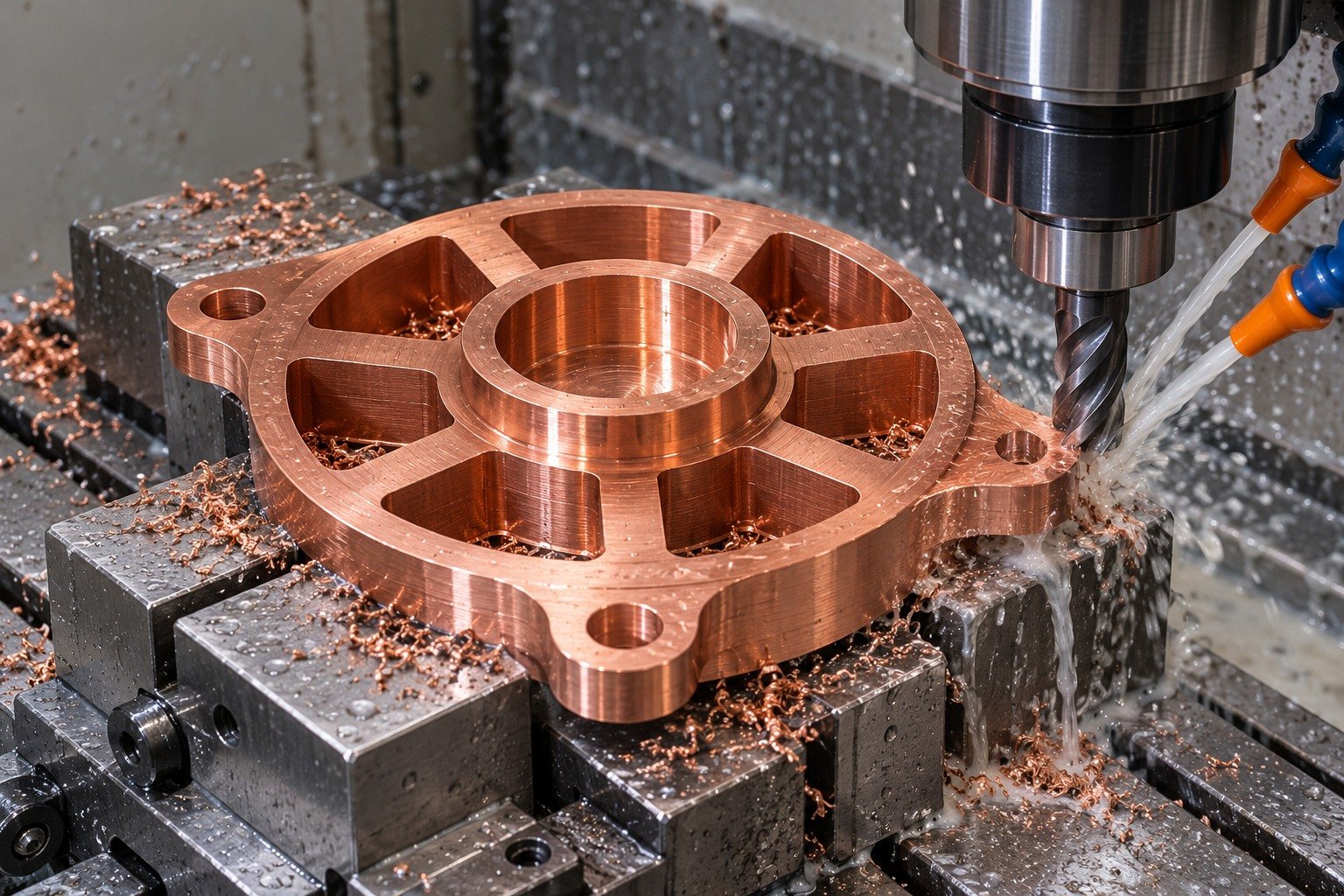
Confirm the actual block or bar stock route. Any secondary heating or forming operation belongs in the agreed manufacturing sequence.
| Your decision | What to define |
|---|---|
| Your fit | Mounting-ear datums, slot access, boss geometry and contact-plane requirements. |
| Your route | Stock condition, support and finishing sequence. |
| Your approval | Final geometry, surface and receiving evidence. |
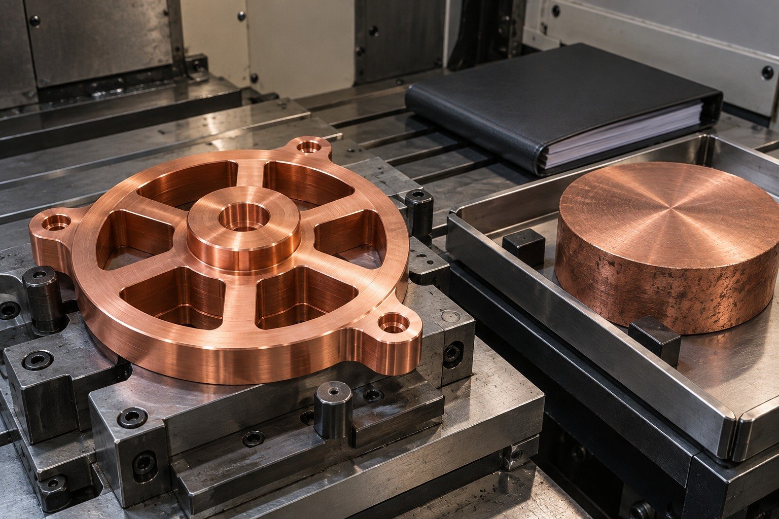
Inspect mounting geometry and the specified contact face. Any complete thermal assembly test needs a separate agreed scope.
| Your decision | What to define |
|---|---|
| Your fit | Mounting-ear datums, slot access, boss geometry and contact-plane requirements. |
| Your route | Stock condition, support and finishing sequence. |
| Your approval | Final geometry, surface and receiving evidence. |

For a right-angle terminal link, define the perpendicular contact lands, oval mounting slot and connection bosses. Confirm the actual current path and assembly clearance before the machining route.
| Your decision | What to define |
|---|---|
| Your fit | Perpendicular land relationship, slot orientation and connection bore location. |
| Your route | Stock condition, support and finishing sequence. |
| Your approval | Final geometry, surface and receiving evidence. |
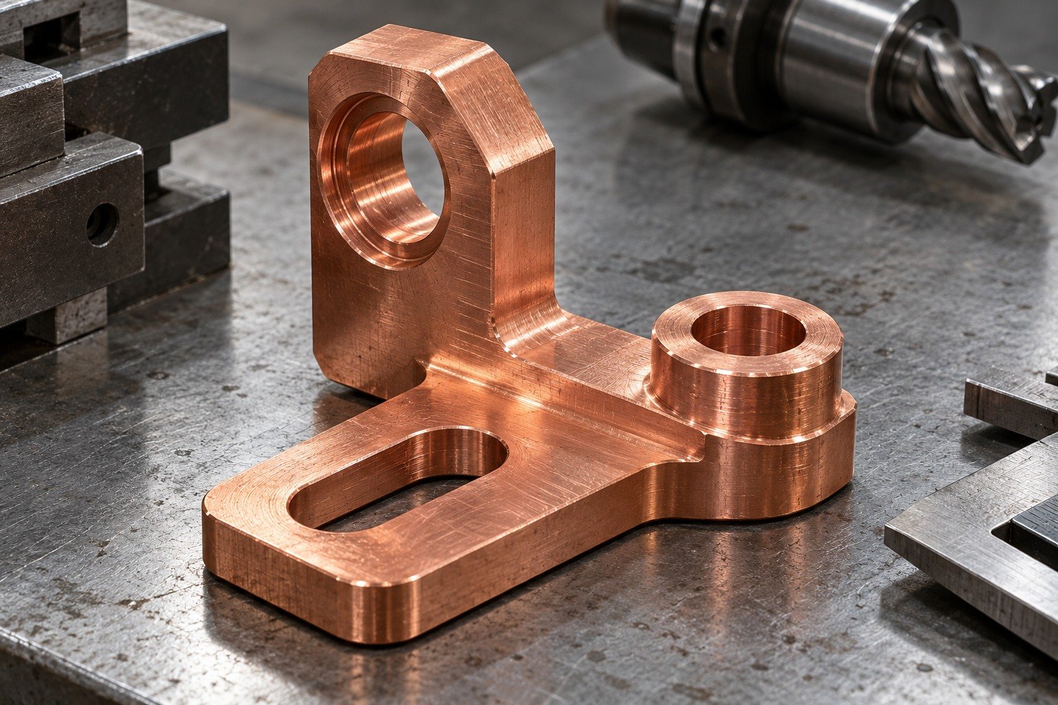
Review C145 copper drilling and C145 copper tapping with chip escape, gauge access and intersecting edge inspection. Keep full contact lands protected.
| Your decision | What to define |
|---|---|
| Your fit | Perpendicular land relationship, slot orientation and connection bore location. |
| Your route | Stock condition, support and finishing sequence. |
| Your approval | Final geometry, surface and receiving evidence. |
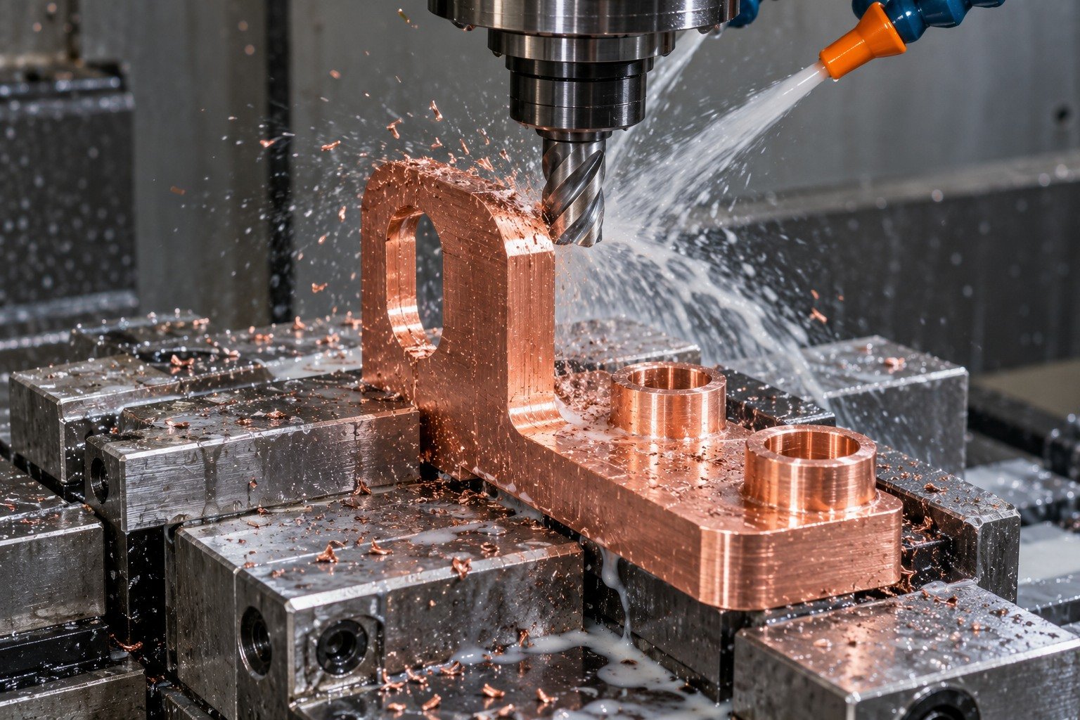
Review whether the shape is machined from solid or includes a separately specified forming step. Confirm the final condition and material identity.
| Your decision | What to define |
|---|---|
| Your fit | Perpendicular land relationship, slot orientation and connection bore location. |
| Your route | Stock condition, support and finishing sequence. |
| Your approval | Final geometry, surface and receiving evidence. |
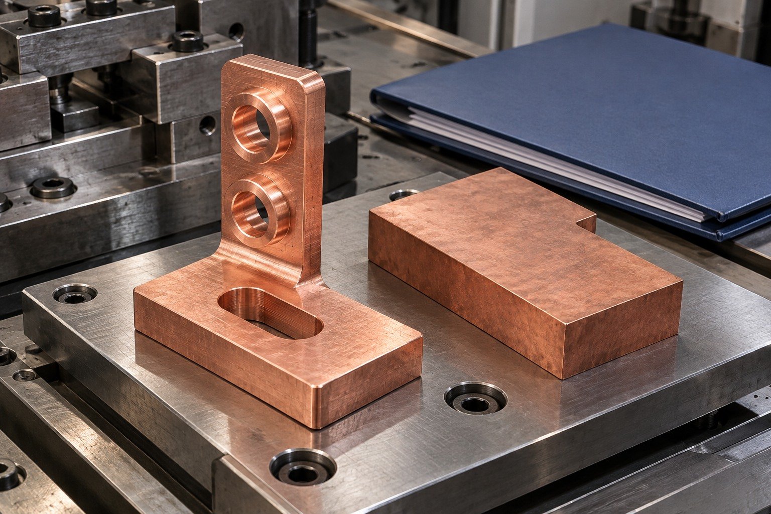
Verify the finished perpendicular datums, slot and connection features. Agree receiving evidence for the same drawing revision.
| Your decision | What to define |
|---|---|
| Your fit | Perpendicular land relationship, slot orientation and connection bore location. |
| Your route | Stock condition, support and finishing sequence. |
| Your approval | Final geometry, surface and receiving evidence. |
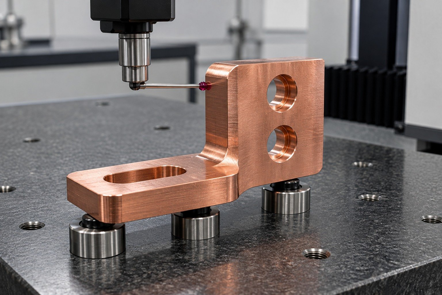
For C145 copper machining services, choose operations against your material state and drawing. Your quote confirms the requested operations, quantities and inspection scope.
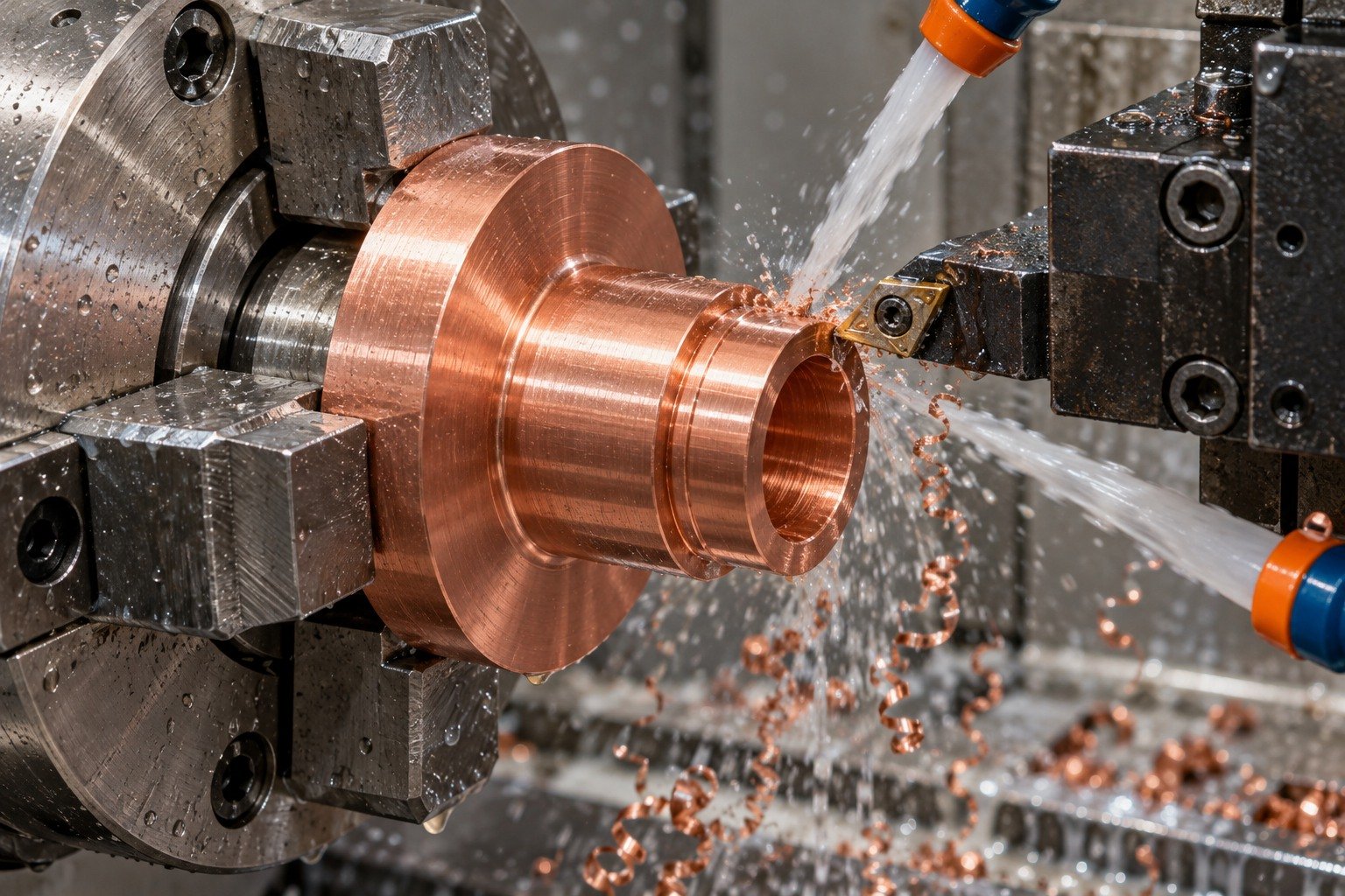
Review shoulder access, chuck engagement and the finished connector bore before turning.
Explore the Process →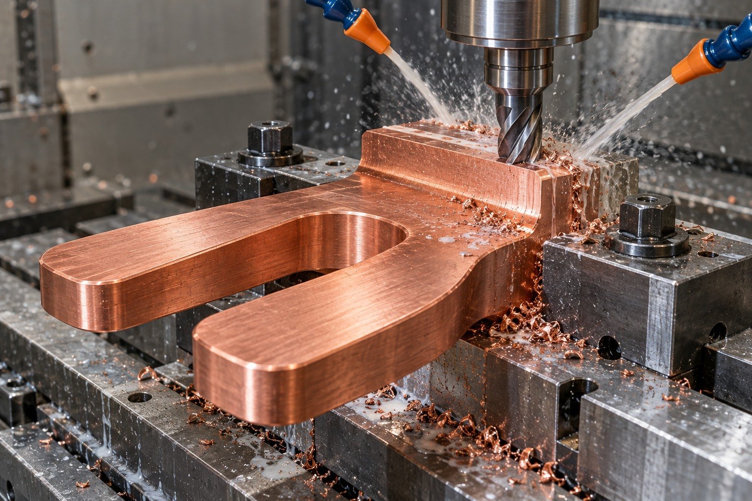
For C145 tellurium copper CNC machining, keep supported tool access and the final contact lands in the same review.
Explore the Process →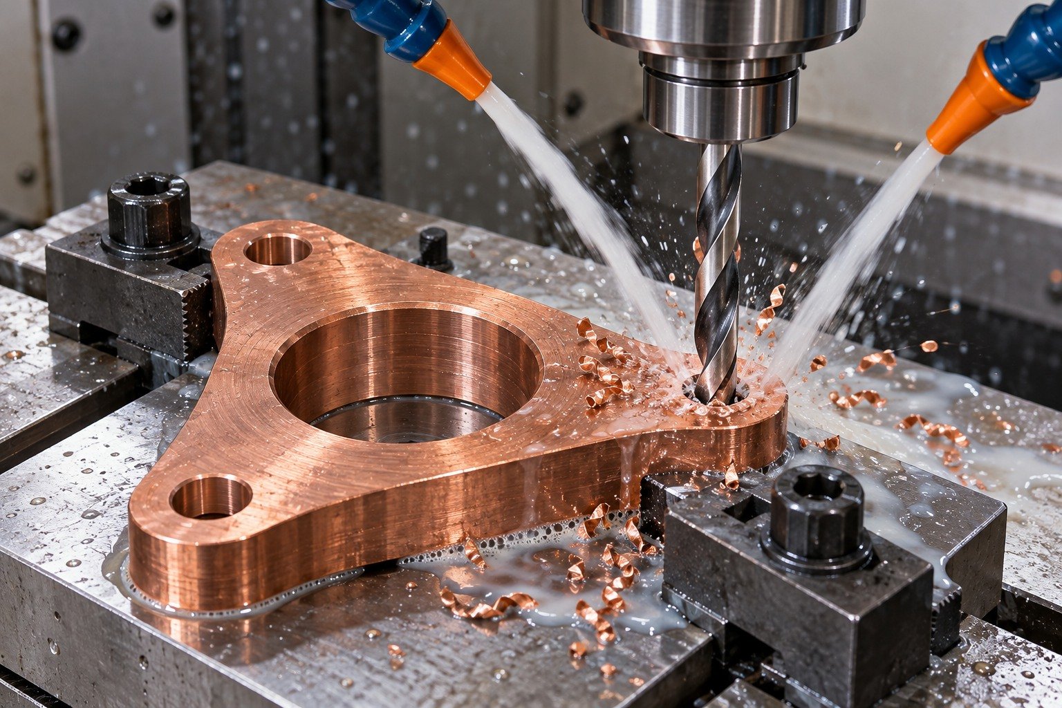
Review hole entry, thread run-out, gauge access and chip removal at each intersection.
Explore the Process →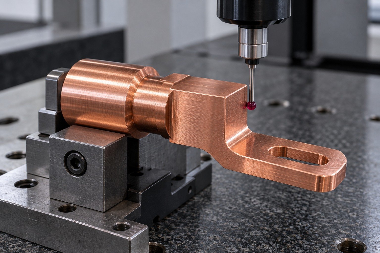
Verify locating datums, critical mating geometry and accepted surface condition.
Explore the Process →Resolve these six drawing decisions before repeating the manufacturing route.
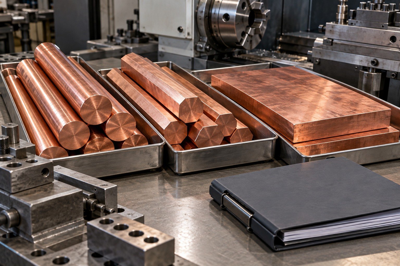
For C145 copper half hard vs soft, name the actual product specification and temper code. Review supplied state, possible forming and the condition of final inspection instead of choosing by an informal hardness label.
Show the working feature and allowed edge condition.
Agree stock, support and final surface.
Inspect the actual finished state.
Mark bore intersections, thread ends and hidden contact edges. Agree gauge access and the specific acceptance method before approving an enclosed connector feature.
Show the working feature and allowed edge condition.
Agree stock, support and final surface.
Inspect the actual finished state.

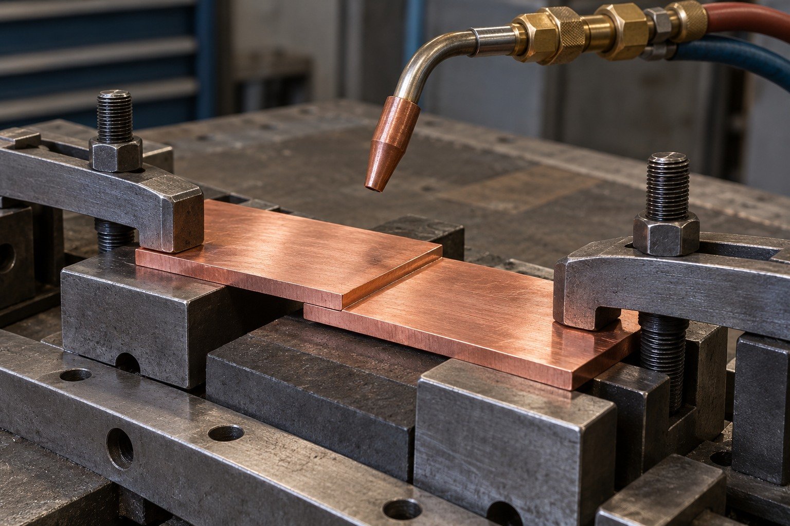
Identify the actual joining process, filler, atmosphere and final condition before agreeing a route. A producer suitability rating does not qualify your joint or establish that the delivered part meets an assembly requirement.
Show the working feature and allowed edge condition.
Agree stock, support and final surface.
Inspect the actual finished state.
For C145 copper deburring, specify reachable internal edges, allowed edge breaks and contact regions that must retain their geometry. Use the first controlled sample to agree acceptance.
Show the working feature and allowed edge condition.
Agree stock, support and final surface.
Inspect the actual finished state.
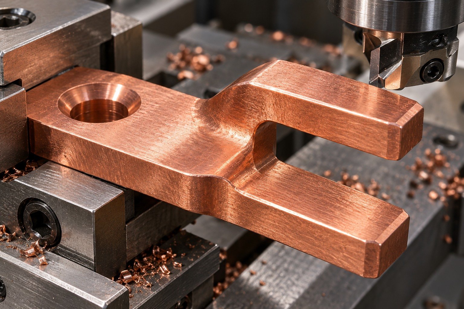
Show roughness, cleaning, masking and handling protection on the functional contact land. Colour and visual brightness do not prove contact resistance or suitability of an unspecified finish.
Show the working feature and allowed edge condition.
Agree stock, support and final surface.
Inspect the actual finished state.
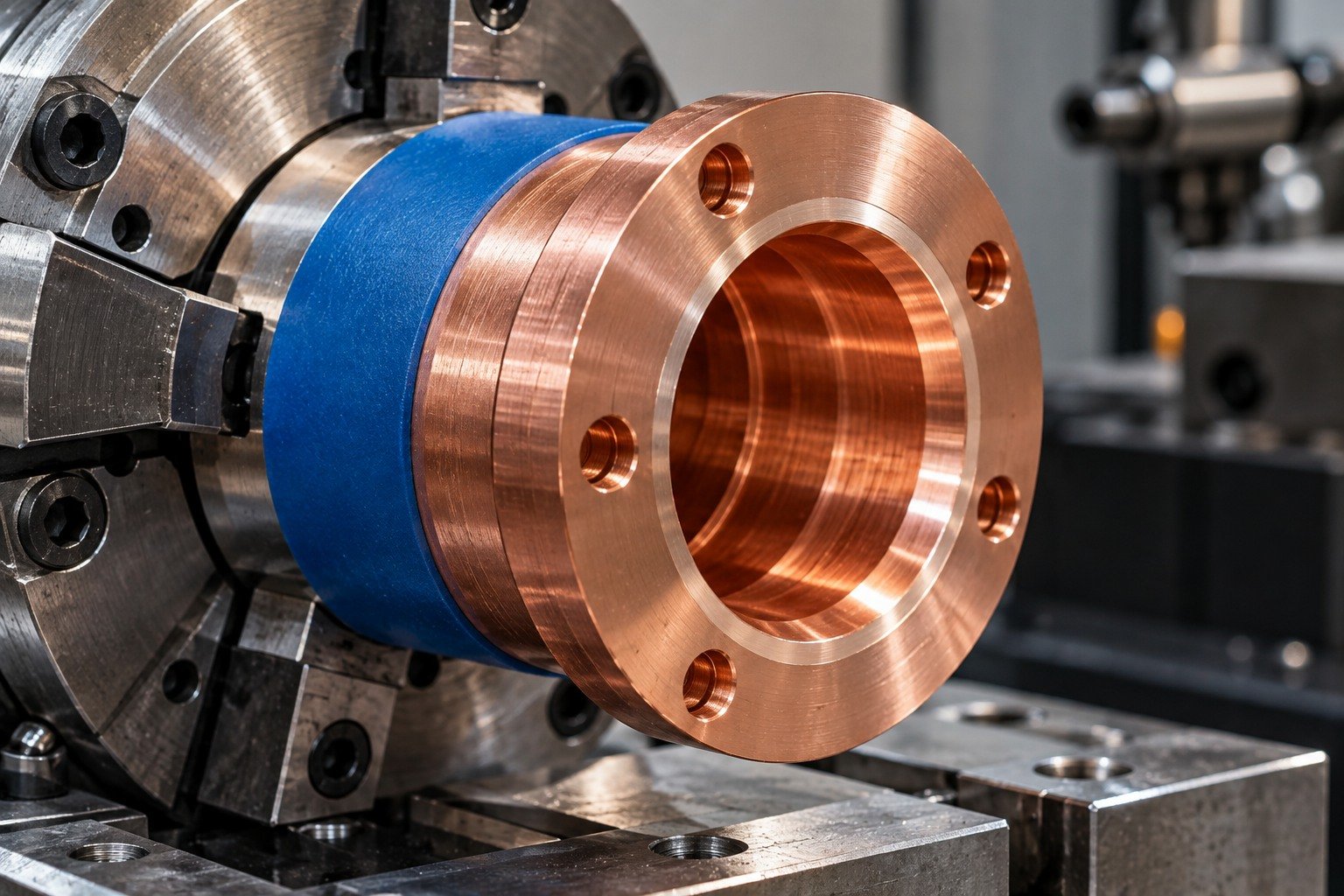
Link each critical tolerance to datums, stock condition and accessible measurement. Confirm the finished state and evidence scope; no single accuracy value applies to every copper feature.
Show the working feature and allowed edge condition.
Agree stock, support and final surface.
Inspect the actual finished state.
| Material review | What to confirm |
|---|---|
| C145 / tellurium copper | Product form, ordered temper, contact geometry and receiving scope. |
| C360 / free-cutting brass | For C145 copper vs C360 brass, compare the full material and functional requirement; neither chart approves replacement. |
| C172 / beryllium copper | For C145 copper vs C172 copper, retain distinct chemistry and any required heat-treatment state; do not confuse tellurium and beryllium copper. |
Approve material changes against your full purchasing requirement and working assembly, before ordering replacement stock.
Compare Copper, Brass & Bronze →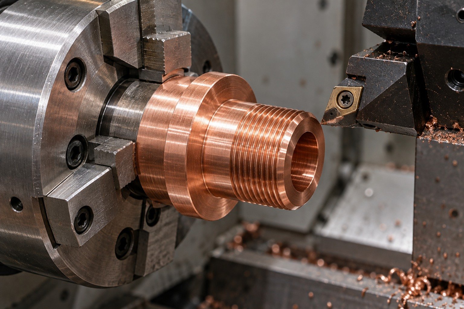


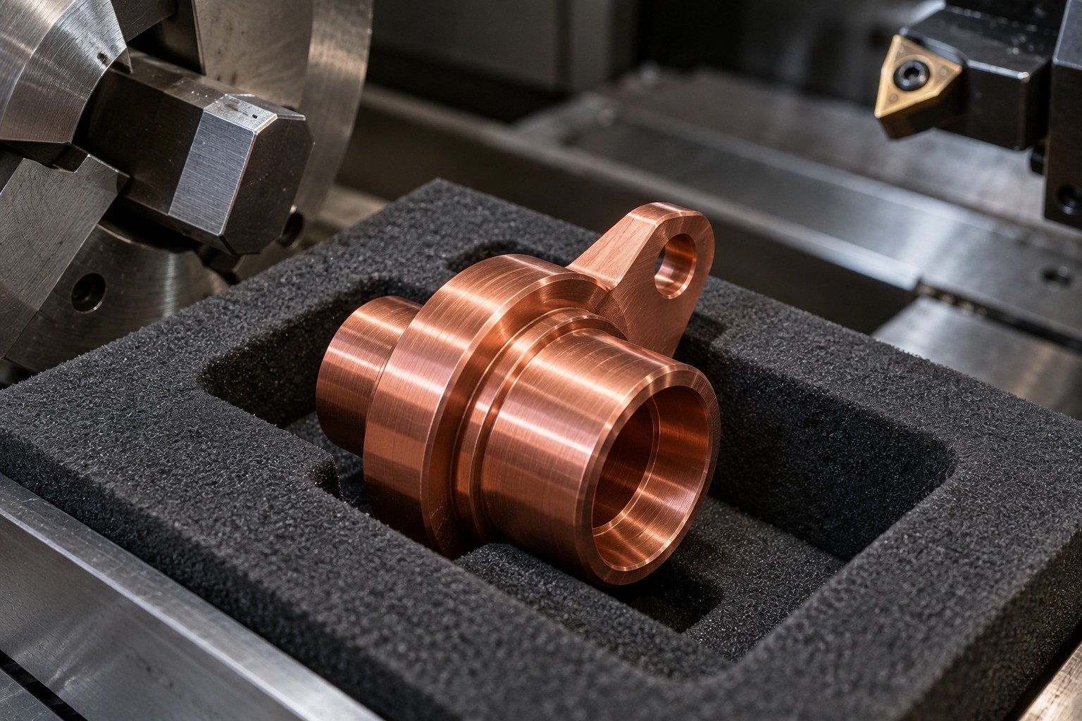
For your C145 copper surface finish, specify the contact land, roughness and delivery protection. These appearances do not promise plating, coating compatibility or electrical performance.
Surface Finishing →Grade, product form, temper and lot.
Contact features and accepted edges.
Final fit, surface and records.
For your C145 copper material certificate, agree document type, lot identity, product standard and supplied temper before purchase. Link the accepted stock to the ordered scope.
Sampling and evidence scope are agreed with your quote.
Quality Assurance →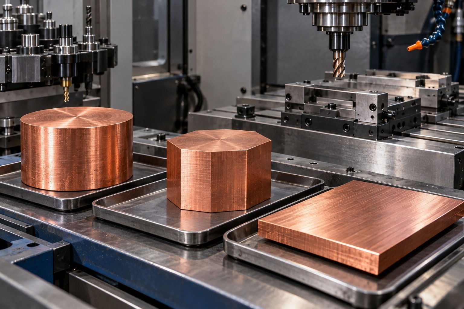
For C145 copper prototype machining, review the first controlled sample against connector fits, contact lands and accepted internal edges. Confirm sample and repeat quantities with your quotation.
Sampling and evidence scope are agreed with your quote.
Quality Assurance →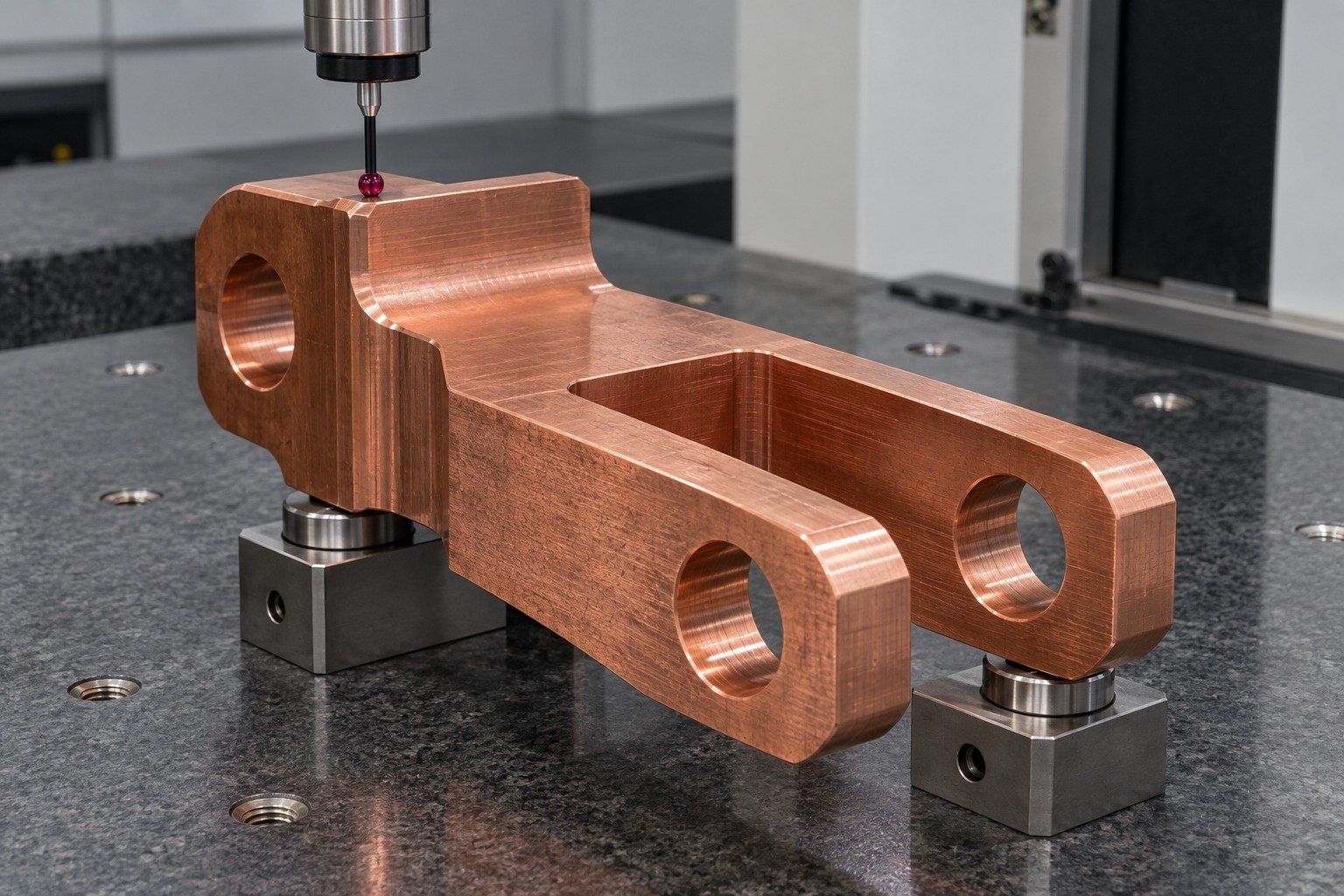
Inspect the final bore-to-shoulder relationship, mounting datums and accepted contact surfaces after all agreed operations. Keep dimensional evidence separate from electrical assembly testing.
Sampling and evidence scope are agreed with your quote.
Quality Assurance →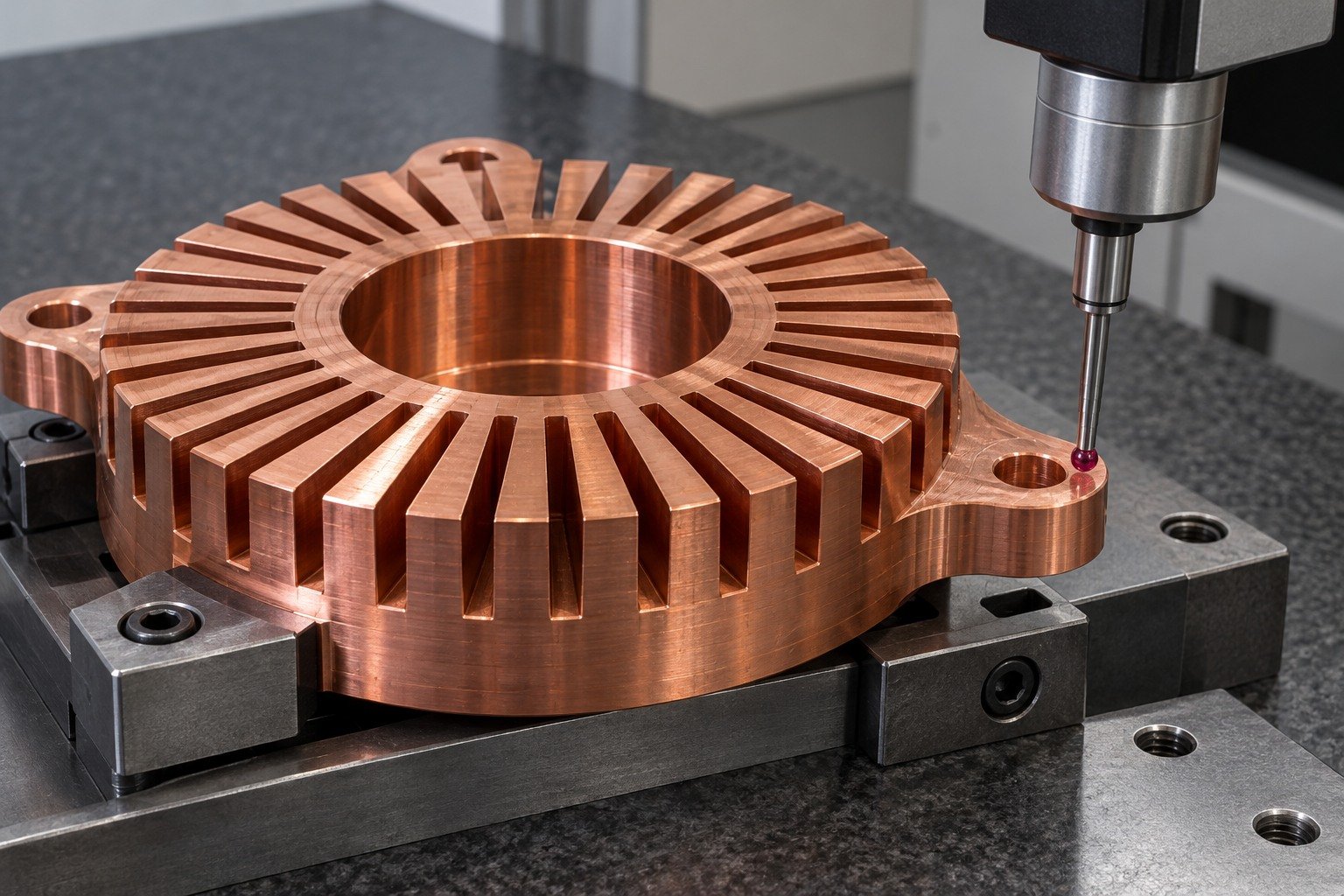
Agree separate protection for exposed contact faces and identify each delivered lot. Confirm which material and dimensional records your receiving team needs.
Sampling and evidence scope are agreed with your quote.
Quality Assurance →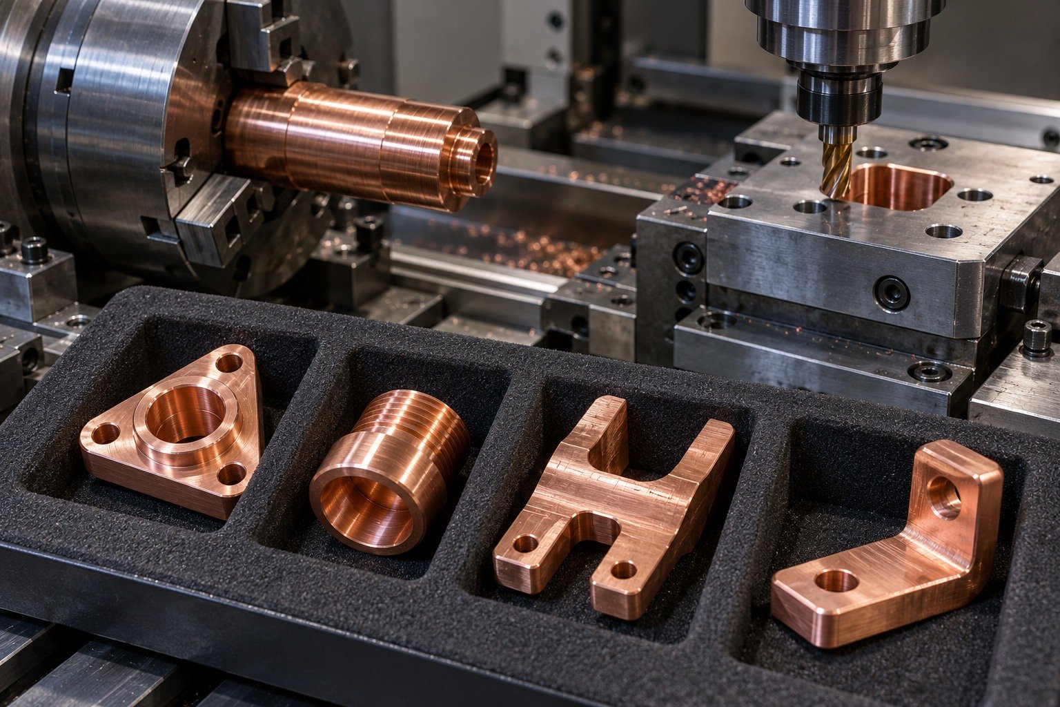

Connect China manufacturing with Dallas-area coordination for drawing review, sample decisions and delivery requirements.
Tellurium is the selected machining addition in the referenced C14500 composition table; that table does not establish zero trace lead. If your product has a lead limit or other material restriction, specify the actual requirement and agreed test evidence before ordering.
Review the actual contact design, stock state, current path, contact pressure and working surface. Reference material conductivity supports a material comparison; it does not qualify your complete connector.
Identify the specific welding process, joint design and final material condition. Producer suitability varies by technique; agree joining responsibility and required qualification before accepting a manufacturing route.
Compare electrical requirements, contact geometry, stock condition, finish and complete material specification. A free-cutting machinability index does not establish equivalent conductivity or approve a substitution.
No automatic substitution follows from the word copper. C145 is tellurium copper; C172 is beryllium copper. Confirm exact chemistry, product form, required state and acceptance with your drawing authority.
Your C145 copper machining cost depends on stock form and usable material, setups, tool access, edge removal, contact protection, quantities and receiving evidence. For a C145 copper machining quote, compare the same drawing revision and final condition.
Specify the exact temper and product standard. Review forming requirements, cutting support and the finished geometry against that state; do not convert informal hardness names into an unverified material substitution.
For your C145 tellurium copper machining review, provide the controlled drawing, stock requirement, critical connector fits, accepted edges, finish and inspection scope. C145 copper milling services and C145 copper turning services must follow the same final acceptance.





