Injection Molding
Tooling and molding for your repeat plastic parts.
From prototype to production, coordinated manufacturing solutions for your custom parts.
View All Services →
Precision parts for your tight tolerances and complex geometry.
Tooling and molding for your repeat plastic parts.

Metal casting options for your part and production volume.

Cutting, forming and welding for your fabricated parts.

Custom profiles for your section, length and finish requirements.

Finishes for your appearance, corrosion and wear requirements.

Sub-assemblies and final builds for your production program.

Production tooling built around your process and volume.

Prototype parts to check fit, function and design.
DFM, process planning and production support for your project.
Inspection, documentation, inventory and delivery planning for your program.
Choose air- or liquid-cooling components around your thermal and mechanical requirements.

Manufacturing support for your cold plates, manifolds and cooling assemblies.

Find components for your power electronics, energy, laser and telecom application.

Components for your electronic systems.
Start with your functional and quality requirements.
Build around your operating environment.
From prototype to production, review material performance, manufacturability and cost for your part.
Review grade, temper and finish for your metal parts.
 AluminumStrength, weight and machining›
 Stainless SteelCorrosion and finish requirements›
 Carbon & Alloy SteelDiscuss grade and heat treatment›
 Tool SteelDiscuss tooling and wear needs›
 TitaniumReview grade and part geometry›
 Copper & Brass & BronzeDiscuss conductivity and machining›
Match your polymer to function, process and environment.
 ABSReview enclosure and molding needs›
 Polycarbonate (PC)Discuss clarity and impact needs›
 Nylon (PA)Review moisture and wear conditions›
 POM / AcetalReview fit and sliding features›
 PEEKDiscuss operating conditions›
 PTFEReview friction and chemical exposure›
 ULTEM / PEIDiscuss thermal and electrical needs›
Confirm grade availability and application requirements.
 Silicone / LSRDiscuss flexible component needs›
 TPU / TPEReview flexibility and processing›
 EPDMReview weathering and chemical exposure.›
 NBRReview oil and fuel exposure.›
 FKMReview temperature and chemical exposure.›
 G10 / FR4Review insulation and laminate needs›
 CompositesReview stiffness, weight and laminate.›Customer-Specified MaterialsConfirm your grade and requirements.›Other Specialty MaterialsDiscuss your application and grade.›
Practical guidance for your part geometry and material decisions.
Prepare your process, budget and sourcing questions.
Build your knowledge before production.
Learn who we are and how we operate.
Find our U.S. support team or start a conversation.
YOUR DATUMS. YOUR CLEANLINESS. YOUR RELEASED DRAWING.
Review your custom semiconductor equipment components around the installed interface, surface condition and required records. Define the manufactured part and sample acceptance before selecting the route.
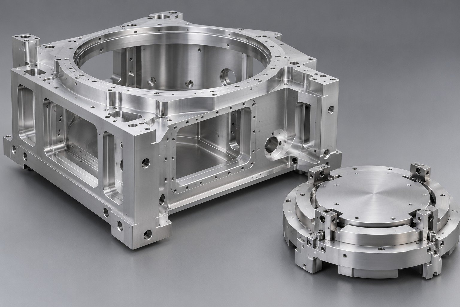
When you compare a semiconductor equipment parts manufacturer, ask how your released drawing, surface requirements and inspection scope will be reviewed.
Identify the housing, support, fixture or mounting component.
Define locating faces, holes and the installed coordinate scheme.
State finish, cleaning, handling and packaging requirements.
Name the records and acceptance owner for your sample.
Review connector openings, cover fit, sealing interfaces and access to internal features.
Your input: assembly envelope, ports and controlled mounting drawing.
Match contact faces and locating bores to the actual equipment interface.
Your input: datum scheme, functional fits and installed loads.
Define the locating sequence and accessible inspection points before manufacture.
Your input: mating-part information, handling state and acceptance criteria.
Manufacturing scope follows your drawing and project review. Equipment certification, cleanroom qualification and wafer-process validation are separate requirements.
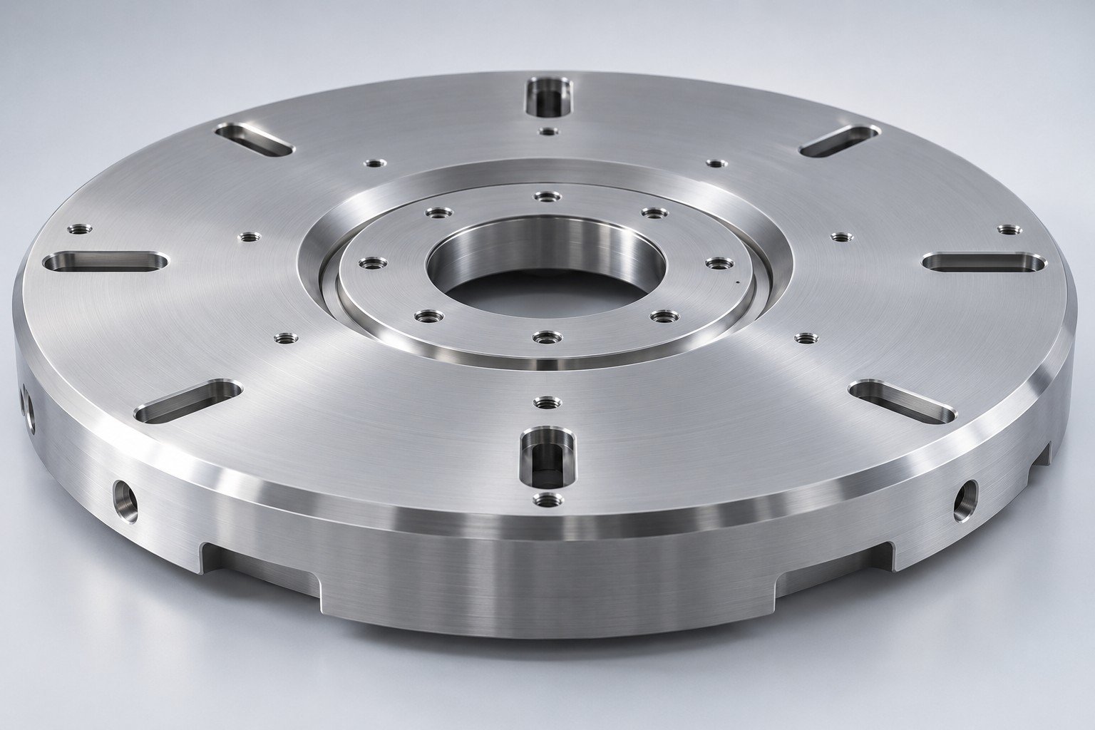
For your semiconductor equipment CNC machining review, identify the relationship between contact planes, locating bores and fastener access. Show the functional tolerances on the drawing rather than applying the same tight limit to every feature.
For semiconductor equipment aluminum components, the locating span and installed temperature matter alongside material identity. The comparison below models free thermal expansion; it is not a measured equipment result.
Uniform heating from 20°C to 100°C · zero baseline, 0–200 µm
ΔL = α × L × ΔT. Inputs: L = 100 mm; ΔT = 80 K; α = 23.58 × 10⁻⁶/K for 6061 and 16.0 × 10⁻⁶/K for 316L. Values rounded to 0.1 µm.
Review the actual span, temperature distribution and mating material.
Include mounting restraint, final coating, protected contacts and accessible inspection features.
This simplified calculation assumes uniform temperature and unconstrained expansion. It does not predict assembly alignment, stress, cleanliness or vacuum performance.
| Material | European reference name | Selected composition | Your purchasing decision |
|---|---|---|---|
| 6061 | EN AW-6061 · AlMg1SiCu | Si 0.40–0.80; Mg 0.80–1.20; Cu 0.15–0.40; Cr 0.04–0.35; Al remainder | Confirm temper, product form, certificate and post-joining condition. |
| 316L / 1.4404 | X2CrNiMo17-12-2 | C ≤0.03; Cr 16.50–18.50; Ni 10.00–13.00; Mo 2.00–2.50; Fe balance | Specify the actual environment, material standard and inspection record. |
Hydro gives a mean 6061 expansion coefficient of 13.1 × 10⁻⁶/°F over 68–212°F; conversion to per kelvin multiplies by 1.8, giving 23.58 × 10⁻⁶/K over 20–100°C. The 316L supplier value is 16.0 × 10⁻⁶/K over the same range. Both are reference inputs, not a material substitution authorization. Selected composition elements only; purchasing specification, product form and final condition govern.
Hydro 6061 · coefficient and composition ↗ thyssenkrupp 316L · coefficient and composition ↗
Define the primary contact plane and the permitted positional relationship.
Identify the mating bore, pins, fasteners and required clearances.
Agree measurement access, sampling and the required record format.
Interface sequence is an explanatory concept, not a tolerance calculation or measured capability result.
Connect each critical feature to the drawing revision, measurement method and agreed acceptance limit.
Specify the material record, final finish, masked interfaces and any additional surface or cleanliness checks.
Agree protection for contact faces, packaging, part identification and the person approving the sample.
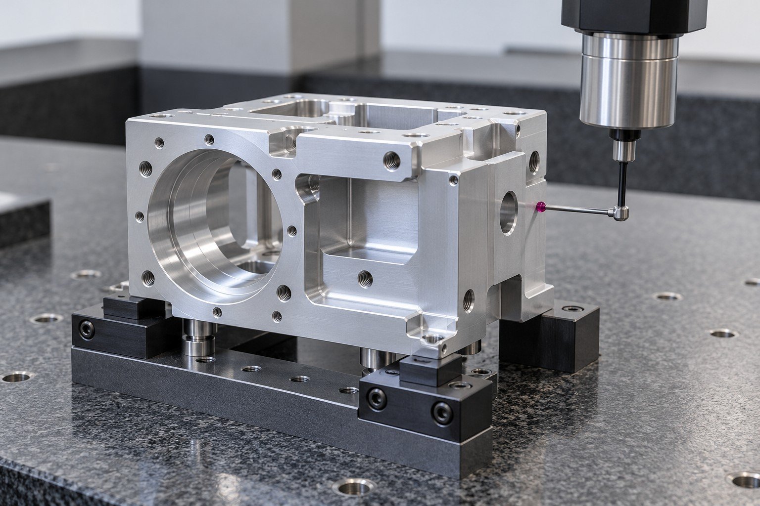
A dimensional report does not establish vacuum performance, particle cleanliness or process compatibility. Specify those validation boundaries separately.
For semiconductor equipment CNC machining, confirm tool access, functional datums and the final material condition before the route is agreed.
Confirm the latest part and assembly revision.
Agree material, machining and finish requirements.
Produce the controlled sample configuration.
Review the required evidence and open issues.
Carry approved requirements into the next build.
Provide CAD, a released 2D drawing with functional datums and tolerances, material and finish specifications, cleaning and packaging requirements, quantities and the required inspection records.
Identify the purchasing material specification, traceability needs, critical dimensions and report format before quotation. The reviewed manufacturing scope confirms which records are included.
Name the required surface state, residues or contamination limits, cleaning method where specified, packaging and acceptance method. Do not assume a general machining quote includes cleanroom or process qualification.
Geometry, stock and material condition, functional tolerances, accessible machining, finish, cleaning, inspection scope and quantity affect the reviewed quote. Send the installed-interface information with your drawing.