

Injection Molding
Tooling and molding for your repeat plastic parts.
From prototype to production, coordinated manufacturing solutions for your custom parts.
View All Services →
Precision parts for your tight tolerances and complex geometry.
Tooling and molding for your repeat plastic parts.

Metal casting options for your part and production volume.

Cutting, forming and welding for your fabricated parts.

Custom profiles for your section, length and finish requirements.

Finishes for your appearance, corrosion and wear requirements.

Sub-assemblies and final builds for your production program.

Production tooling built around your process and volume.

Prototype parts to check fit, function and design.
DFM, process planning and production support for your project.
Inspection, documentation, inventory and delivery planning for your program.
Choose air- or liquid-cooling components around your thermal and mechanical requirements.

Manufacturing support for your cold plates, manifolds and cooling assemblies.

Find components for your power electronics, energy, laser and telecom application.

Components for your electronic systems.
Start with your functional and quality requirements.
Build around your operating environment.
From prototype to production, review material performance, manufacturability and cost for your part.
Review grade, temper and finish for your metal parts.
 AluminumStrength, weight and machining›
 Stainless SteelCorrosion and finish requirements›
 Carbon & Alloy SteelDiscuss grade and heat treatment›
 Tool SteelDiscuss tooling and wear needs›
 TitaniumReview grade and part geometry›
 Copper & Brass & BronzeDiscuss conductivity and machining›
Match your polymer to function, process and environment.
 ABSReview enclosure and molding needs›
 Polycarbonate (PC)Discuss clarity and impact needs›
 Nylon (PA)Review moisture and wear conditions›
 POM / AcetalReview fit and sliding features›
 PEEKDiscuss operating conditions›
 PTFEReview friction and chemical exposure›
 ULTEM / PEIDiscuss thermal and electrical needs›
Confirm grade availability and application requirements.
 Silicone / LSRDiscuss flexible component needs›
 TPU / TPEReview flexibility and processing›
 EPDMReview weathering and chemical exposure.›
 NBRReview oil and fuel exposure.›
 FKMReview temperature and chemical exposure.›
 G10 / FR4Review insulation and laminate needs›
 CompositesReview stiffness, weight and laminate.›Customer-Specified MaterialsConfirm your grade and requirements.›Other Specialty MaterialsDiscuss your application and grade.›
Practical guidance for your part geometry and material decisions.
Prepare your process, budget and sourcing questions.
Build your knowledge before production.
Learn who we are and how we operate.
Find our U.S. support team or start a conversation.
For your C172 beryllium copper machining services quote, define supplied temper, aging route and final fit. Confirm the material-specific process review.
For C17200 CNC machining, keep material identity, product form and the required final condition together. A C172 label alone does not define the acceptance of your finished contact or bushing.
| Identifier | Your purchasing input |
|---|---|
| UNS | C17200 copper / UNS C17200 |
| Common name | Beryllium copper C17200 / copper beryllium alloy |
| European reference | CuBe2 / CW101C / 2.1247 · compare complete standard |
| Ordered material | Form, temper and producer specification |
| Acceptance state | Supplied, after specified aging and finished dimensions |
| Selected rod/bar composition | wt.% |
|---|---|
| Beryllium (Be) | 1.80–2.00 |
| Nickel + cobalt | ≥0.20 |
| Nickel + cobalt + iron | ≤0.60 |
| Copper | Balance |
Materion Alloy 25 rod/bar reference. The Ni + Co and Ni + Co + Fe groups overlap and must not be added as independent quantities. This is not a lot analysis.
| State | Your decision |
|---|---|
| Supplied stock | Identify the actual temper and usable stock. |
| After specified treatment | Agree the final condition, records and remaining stock allowance. |
| Finished geometry | Verify contact fits and locating datums after the complete route. |
Keep rod/bar and strip data distinct. These producer ranges and ratings help frame a material review; they do not approve a different alloy, temper or finished-part performance.
Selected Materion precipitation-aged references · % IACS · scale 0–35
Selected NGK published relative ratings · common scale 0–100%
Conductivity ranges are selected precipitation-age-hardened Materion references for different product forms. NGK reports relative machinability ratings of 20% for C17200 and 60% for its lead-bearing C17300 comparison. Neither chart is a lot result, cutting setting, cycle-time or cost ratio. Confirm the actual ordered form and state.
Materion Alloy 25 references ↗ Wieland CuBe2 / CW101C reference ↗ NGK C17200 / C17300 comparison ↗
Choose the working contact, bushing or connector geometry, then review its route and final condition.
For your custom C17200 parts, connect a slotted contact socket to the actual mating diameter, slot-root geometry and locating shoulder. Your design must define contact force and the required working state.
| Your decision | What to define |
|---|---|
| Your fit | Bore fit, slot-root radius, shoulder position and accepted contact edges. |
| Your route | Stock condition, support and finishing sequence. |
| Your approval | Final geometry, surface and receiving evidence. |
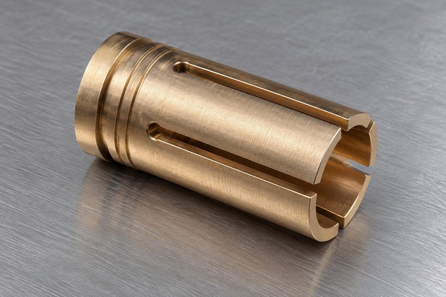
Review C17200 turning and C17200 threading as distinct route steps. For connector mounting features, plan supported milling access, accepted edges and the material-specific process review.
| Your decision | What to define |
|---|---|
| Your fit | Bore fit, slot-root radius, shoulder position and accepted contact edges. |
| Your route | Stock condition, support and finishing sequence. |
| Your approval | Final geometry, surface and receiving evidence. |

Identify the supplied and final condition. Any C17200 age hardening step belongs in the controlled route and must precede acceptance of final fit.
| Your decision | What to define |
|---|---|
| Your fit | Bore fit, slot-root radius, shoulder position and accepted contact edges. |
| Your route | Stock condition, support and finishing sequence. |
| Your approval | Final geometry, surface and receiving evidence. |
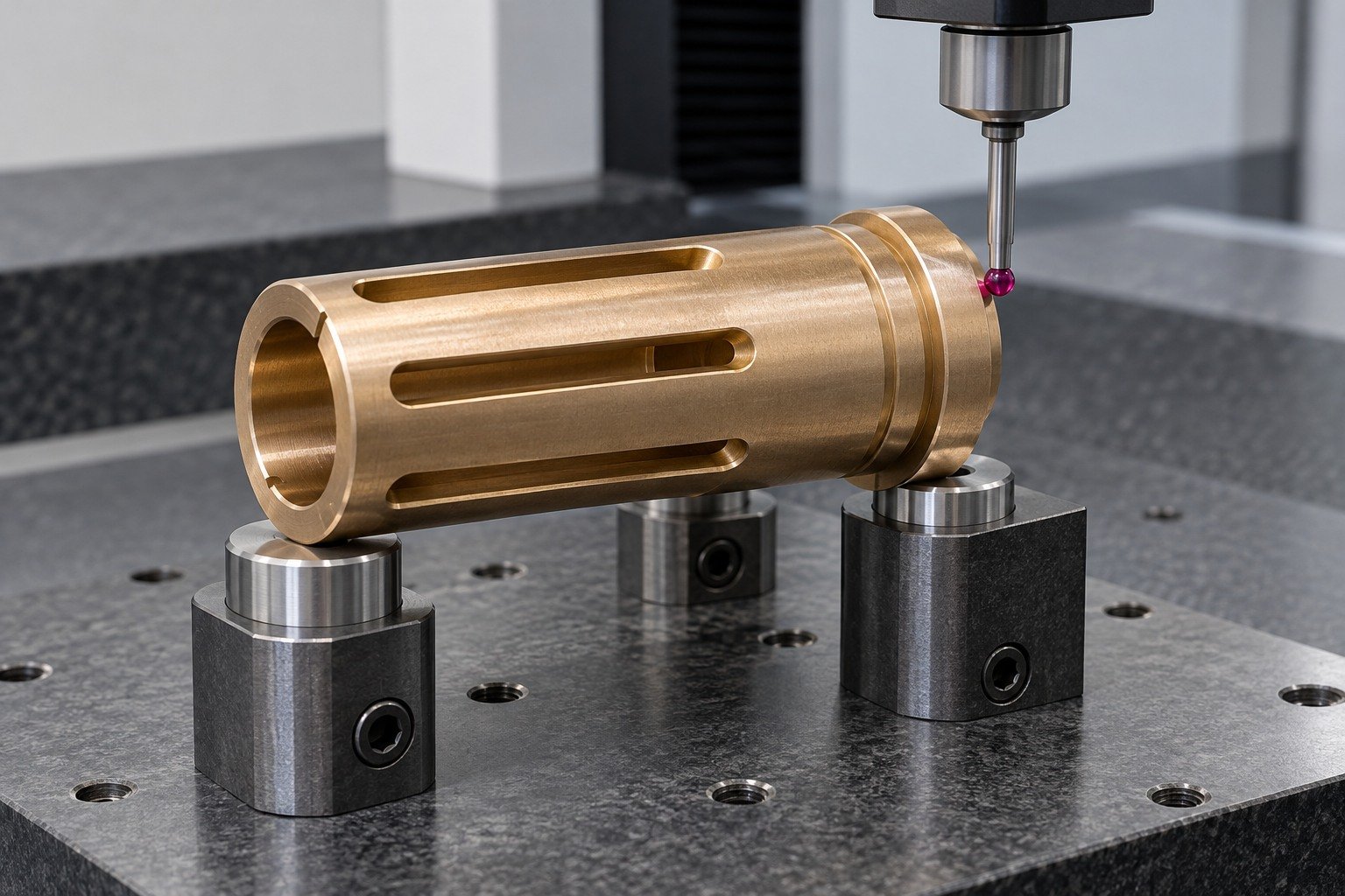
Inspect the final mating diameter and slot relationships. Dimensional evidence does not replace a specified contact-force or electrical assembly test.
| Your decision | What to define |
|---|---|
| Your fit | Bore fit, slot-root radius, shoulder position and accepted contact edges. |
| Your route | Stock condition, support and finishing sequence. |
| Your approval | Final geometry, surface and receiving evidence. |
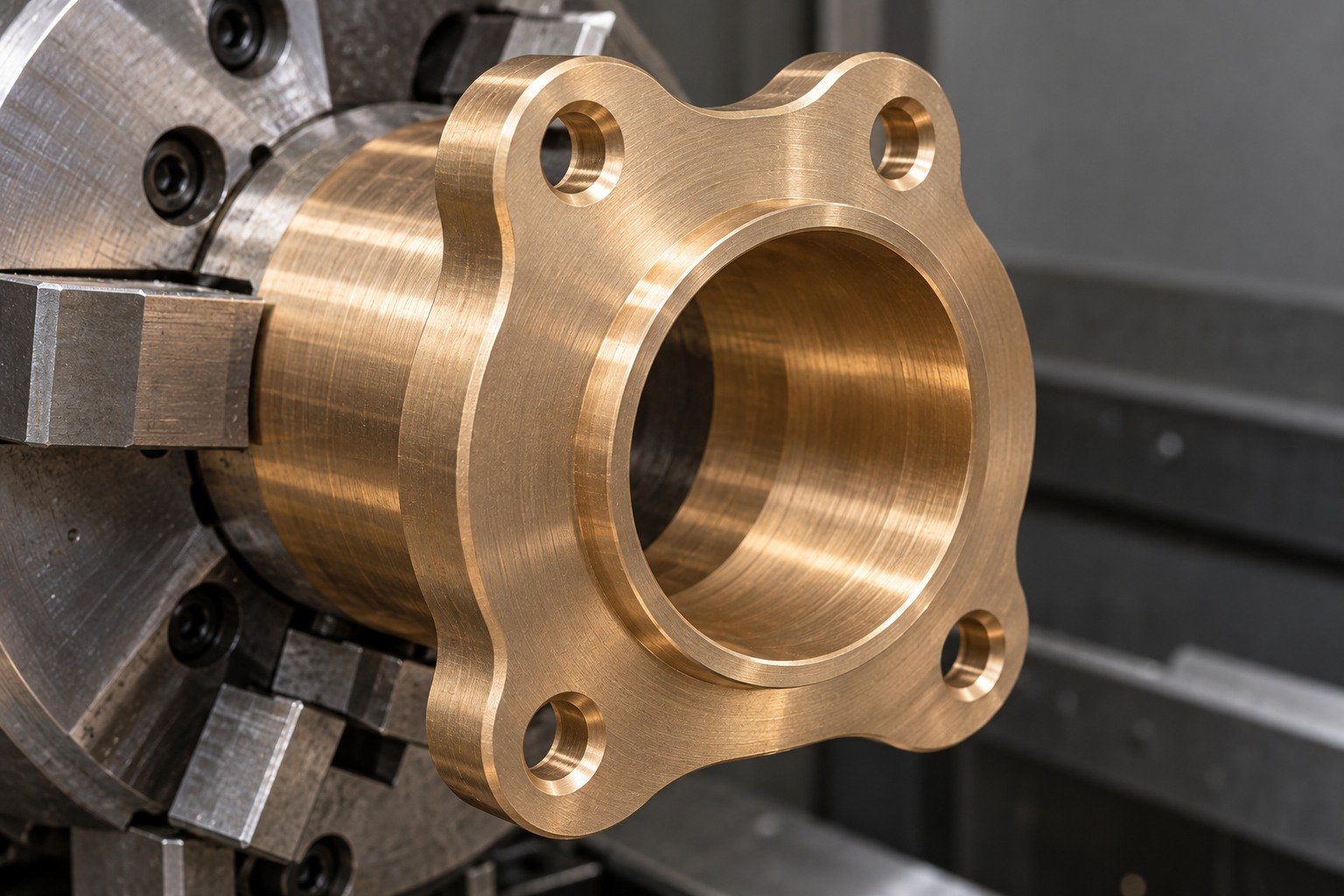
Define a flanged bushing by its bore, mounting-ear pattern and the actual mating shaft. Material grade does not set your required running clearance or wear performance.
| Your decision | What to define |
|---|---|
| Your fit | Bore size, mounting datums, flange thickness and any specified groove. |
| Your route | Stock condition, support and finishing sequence. |
| Your approval | Final geometry, surface and receiving evidence. |
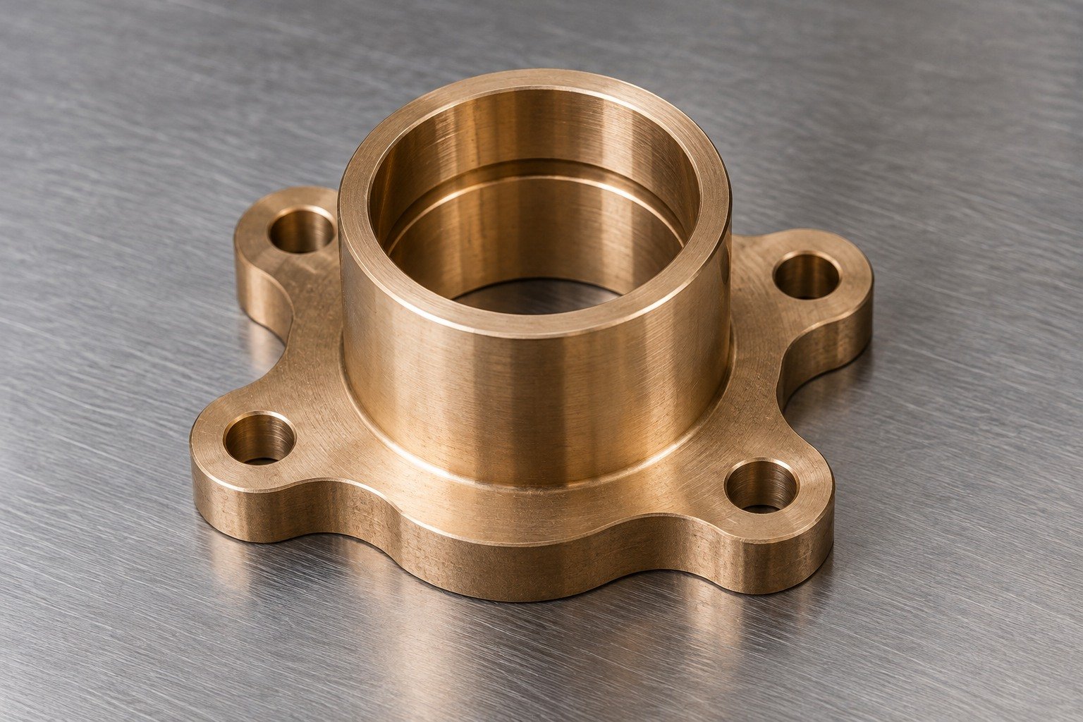
Review chuck or fixture support, internal tool reach and burr-sensitive intersections. Agree material-specific processing and inspection before the quote is released.
| Your decision | What to define |
|---|---|
| Your fit | Bore size, mounting datums, flange thickness and any specified groove. |
| Your route | Stock condition, support and finishing sequence. |
| Your approval | Final geometry, surface and receiving evidence. |
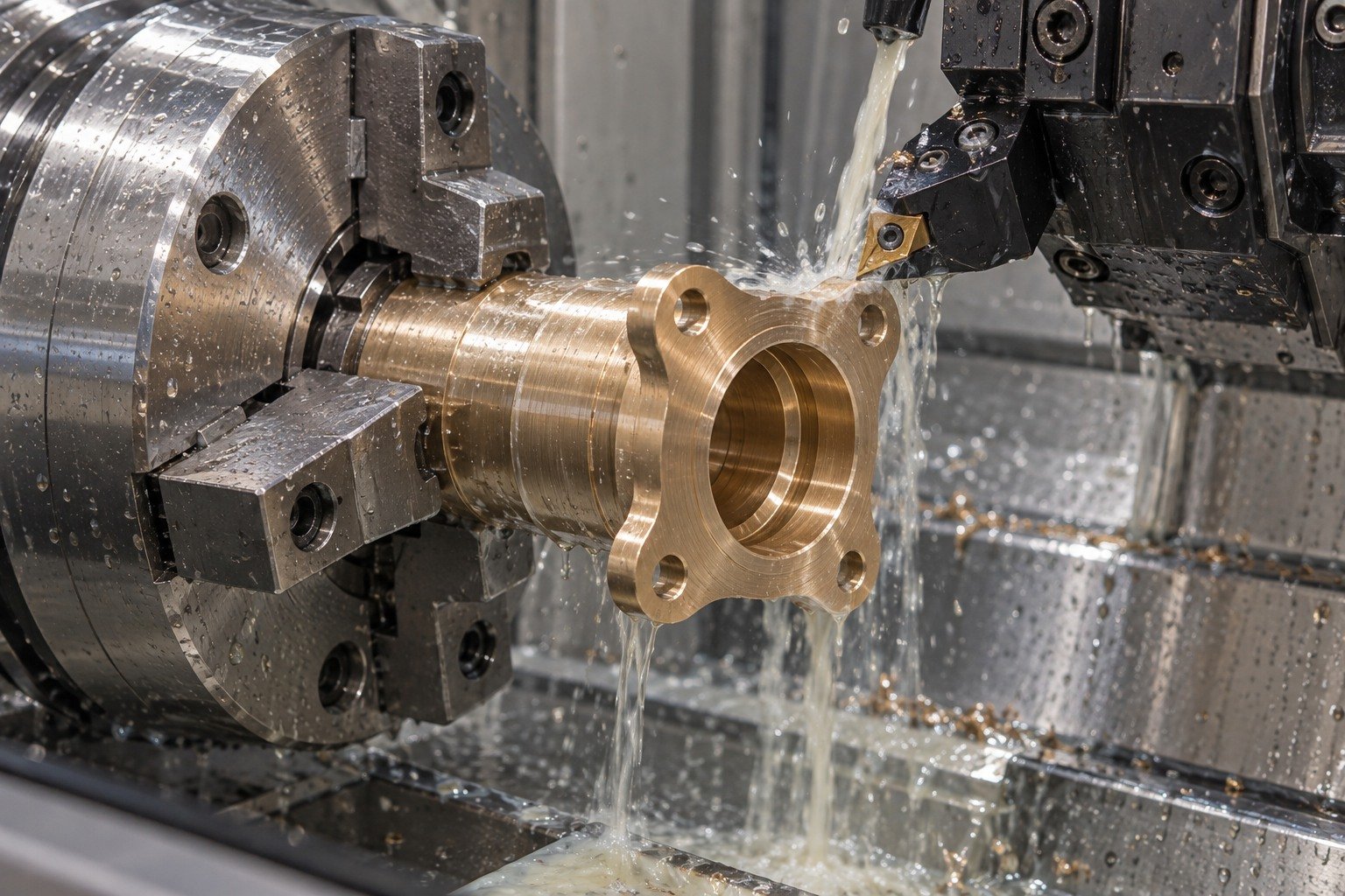
Keep supplied stock and final treatment state on the same record. Review remaining finishing allowance around the bore and locating shoulder.
| Your decision | What to define |
|---|---|
| Your fit | Bore size, mounting datums, flange thickness and any specified groove. |
| Your route | Stock condition, support and finishing sequence. |
| Your approval | Final geometry, surface and receiving evidence. |
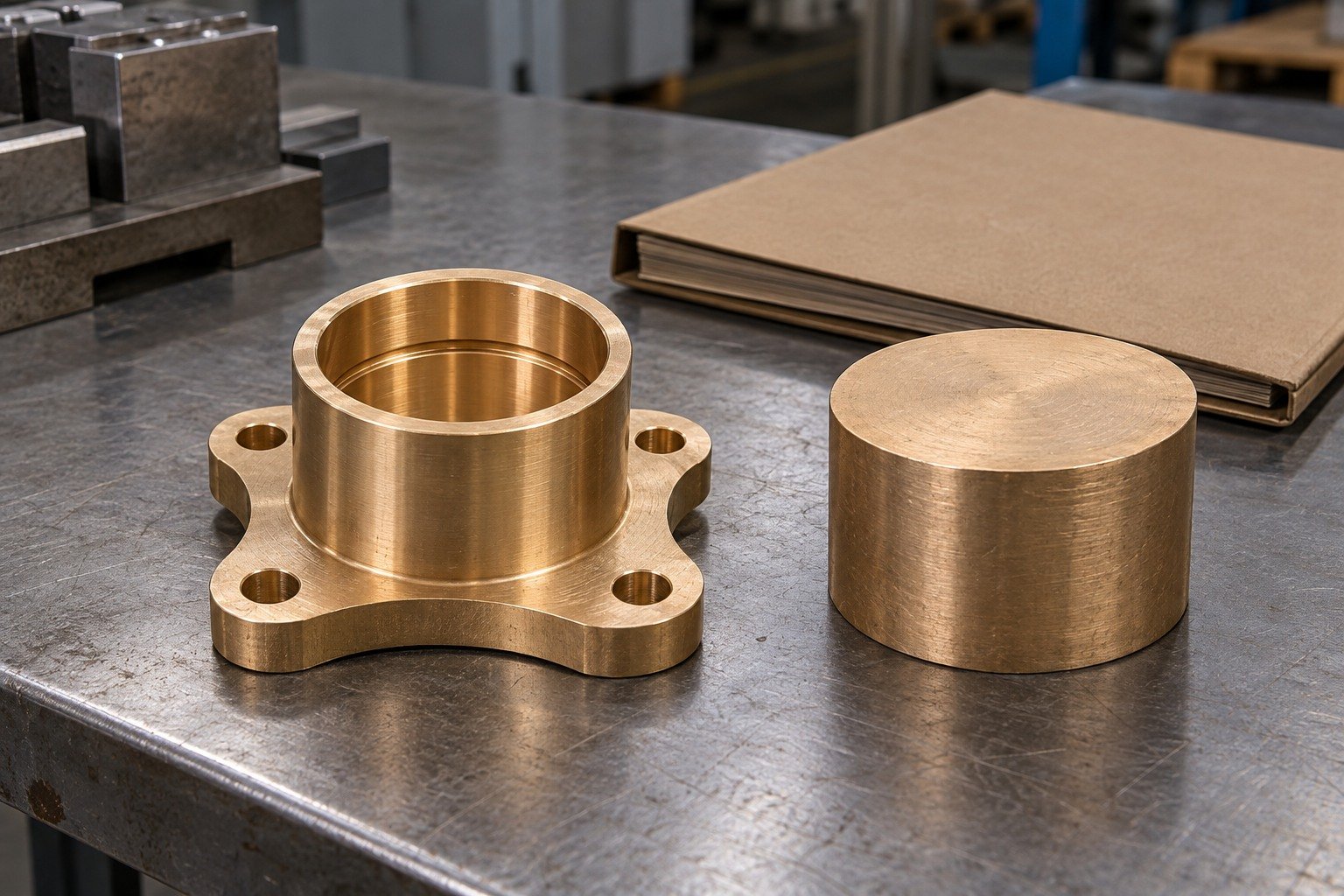
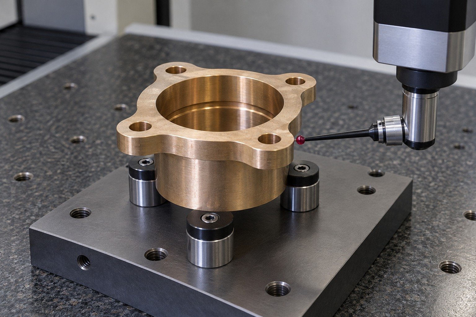
Verify bore-to-flange relationships after the complete route. Agree gauges, measurement access and the exact receiving evidence.
| Your decision | What to define |
|---|---|
| Your fit | Bore size, mounting datums, flange thickness and any specified groove. |
| Your route | Stock condition, support and finishing sequence. |
| Your approval | Final geometry, surface and receiving evidence. |
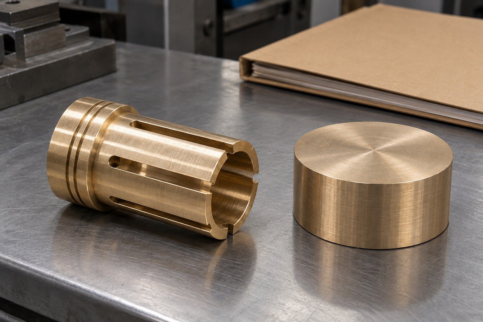
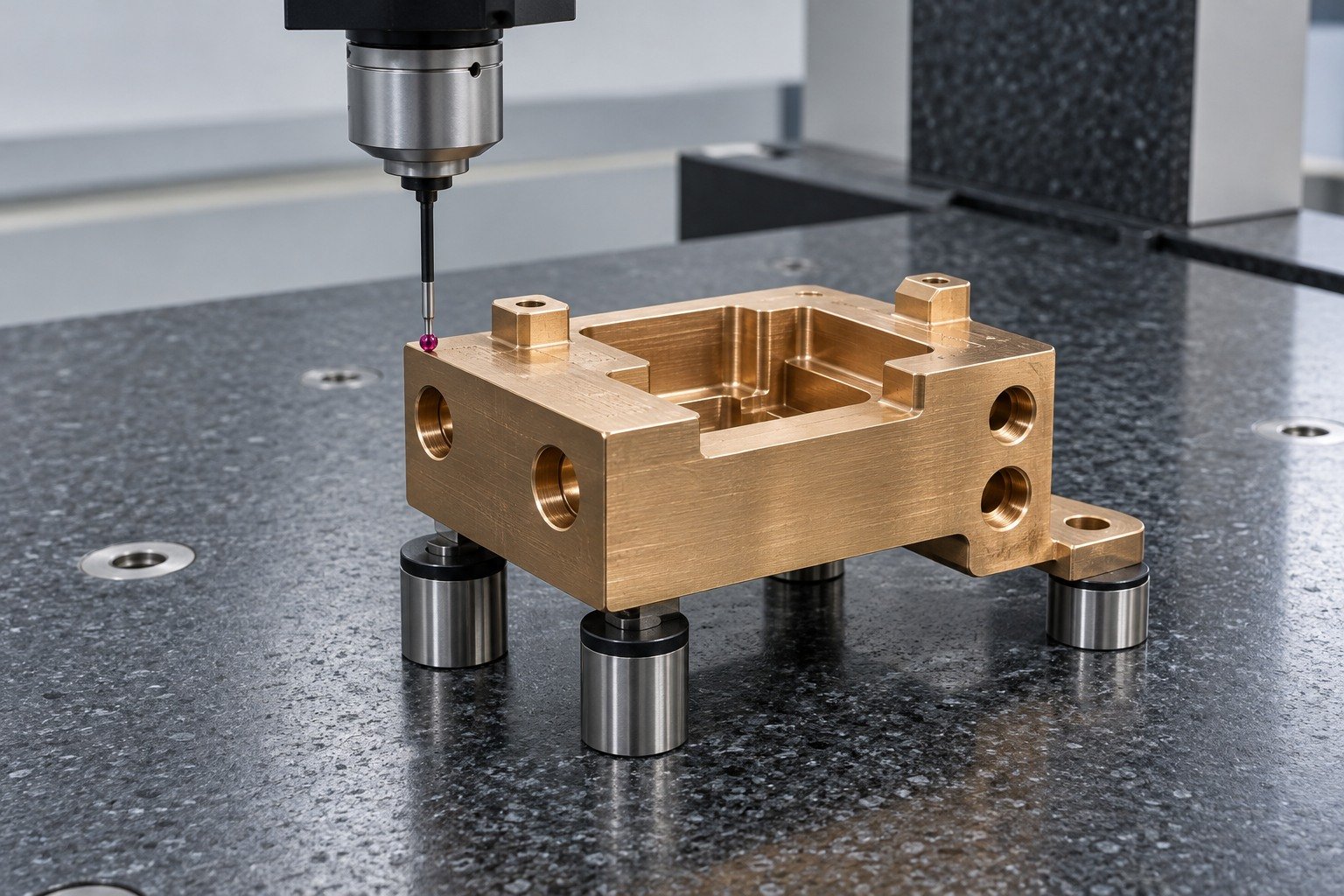
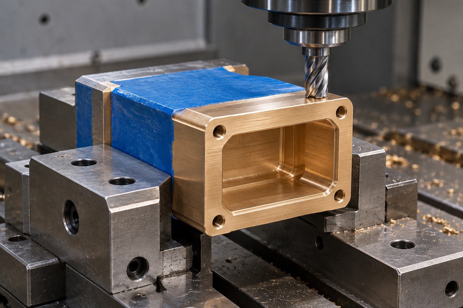
For C17200 connector machining, define a recessed body by its locating pads, side ports and mounting foot. Keep the complete mating requirement visible when choosing the route.
| Your decision | What to define |
|---|---|
| Your fit | Pocket access, port positions, pad heights and mounting-foot datum. |
| Your route | Stock condition, support and finishing sequence. |
| Your approval | Final geometry, surface and receiving evidence. |

For C17200 milling, review engagement around the pocket and solid support below the mounting foot. Confirm the approved material-specific process controls.
| Your decision | What to define |
|---|---|
| Your fit | Pocket access, port positions, pad heights and mounting-foot datum. |
| Your route | Stock condition, support and finishing sequence. |
| Your approval | Final geometry, surface and receiving evidence. |
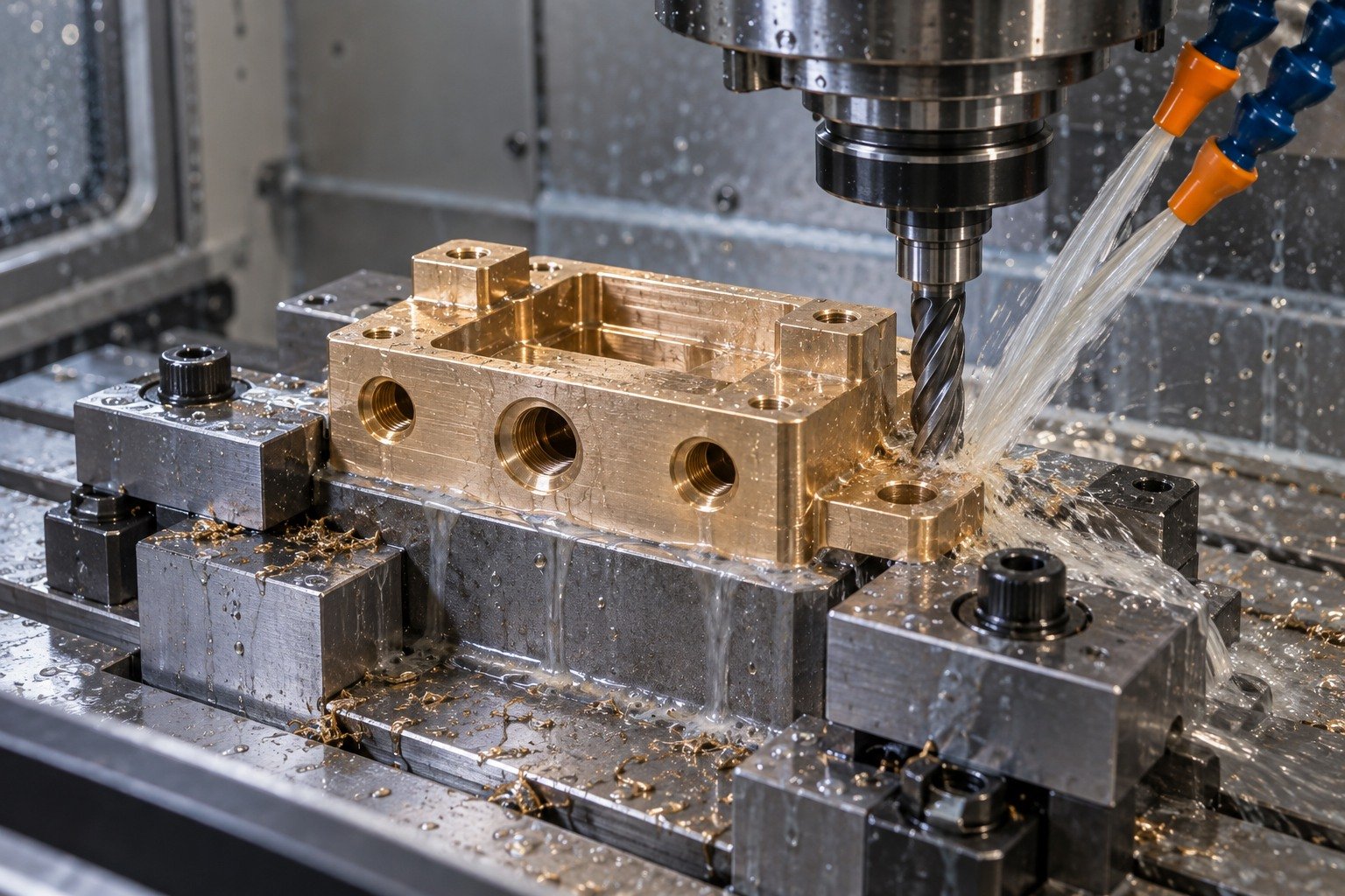
Confirm whether machining precedes or follows the specified treatment. Any change in sequence needs a final-fit and remaining-stock review.
| Your decision | What to define |
|---|---|
| Your fit | Pocket access, port positions, pad heights and mounting-foot datum. |
| Your route | Stock condition, support and finishing sequence. |
| Your approval | Final geometry, surface and receiving evidence. |
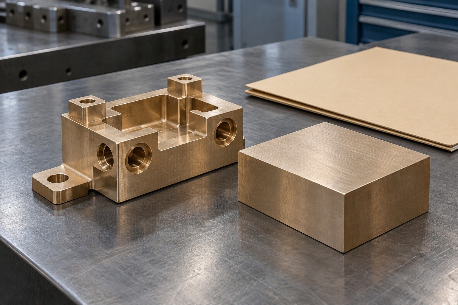
Inspect locating pads, port relationships and accepted surface condition. Separate dimensional acceptance from the complete connector test.
| Your decision | What to define |
|---|---|
| Your fit | Pocket access, port positions, pad heights and mounting-foot datum. |
| Your route | Stock condition, support and finishing sequence. |
| Your approval | Final geometry, surface and receiving evidence. |
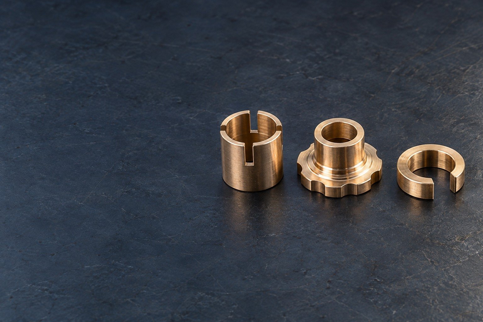
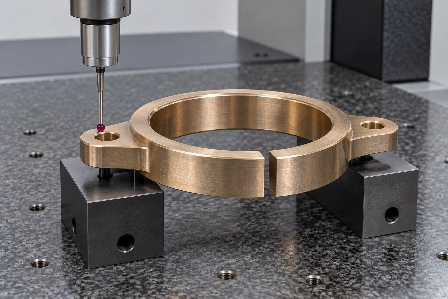
A split-ring contact concept shows a possible compliant geometry, not a verified spring design. Define the working deflection, contact force, final condition and any required fatigue assessment in your specification.
| Your decision | What to define |
|---|---|
| Your fit | Radial gap, minimum section, mounting datums and functional edge condition. |
| Your route | Stock condition, support and finishing sequence. |
| Your approval | Final geometry, surface and receiving evidence. |
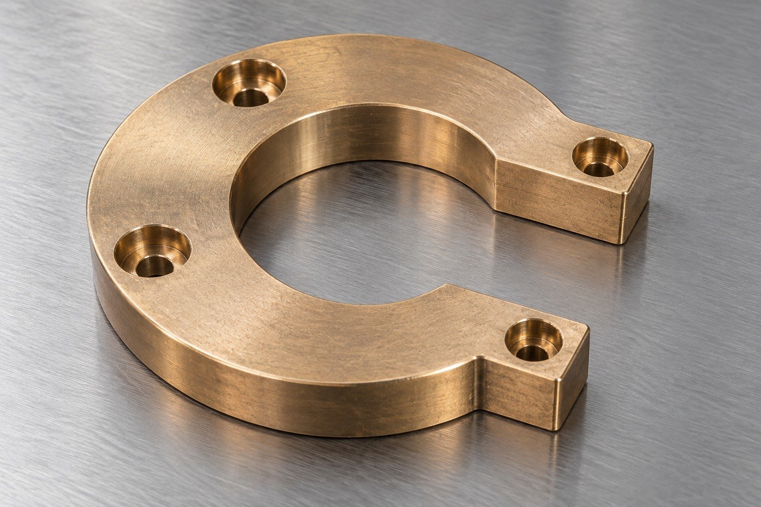
For C17200 precision machining review, agree access, support and the route for gap and slot roots. Do not treat visual symmetry as proof of stress or fatigue performance.
| Your decision | What to define |
|---|---|
| Your fit | Radial gap, minimum section, mounting datums and functional edge condition. |
| Your route | Stock condition, support and finishing sequence. |
| Your approval | Final geometry, surface and receiving evidence. |
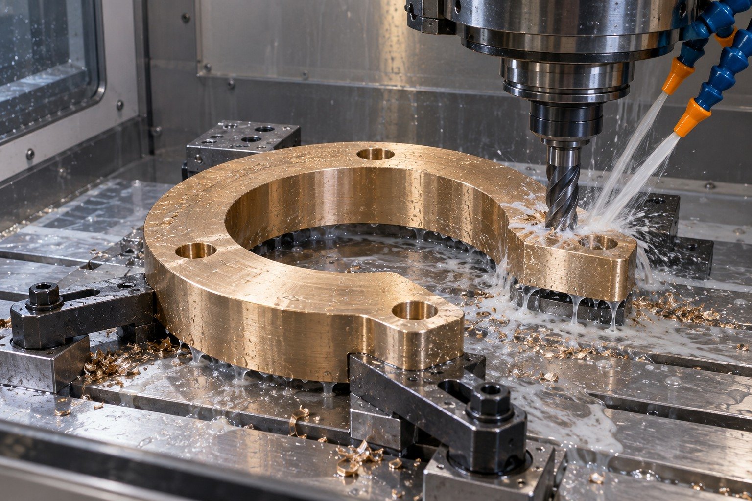
Tie the final spring requirement to the actual material condition and any treatment record. Review distortion and the stock left for final sizing.
| Your decision | What to define |
|---|---|
| Your fit | Radial gap, minimum section, mounting datums and functional edge condition. |
| Your route | Stock condition, support and finishing sequence. |
| Your approval | Final geometry, surface and receiving evidence. |

Verify mounting geometry and gap in the final state. Any force, deflection or fatigue test requires a separate agreed scope.
| Your decision | What to define |
|---|---|
| Your fit | Radial gap, minimum section, mounting datums and functional edge condition. |
| Your route | Stock condition, support and finishing sequence. |
| Your approval | Final geometry, surface and receiving evidence. |
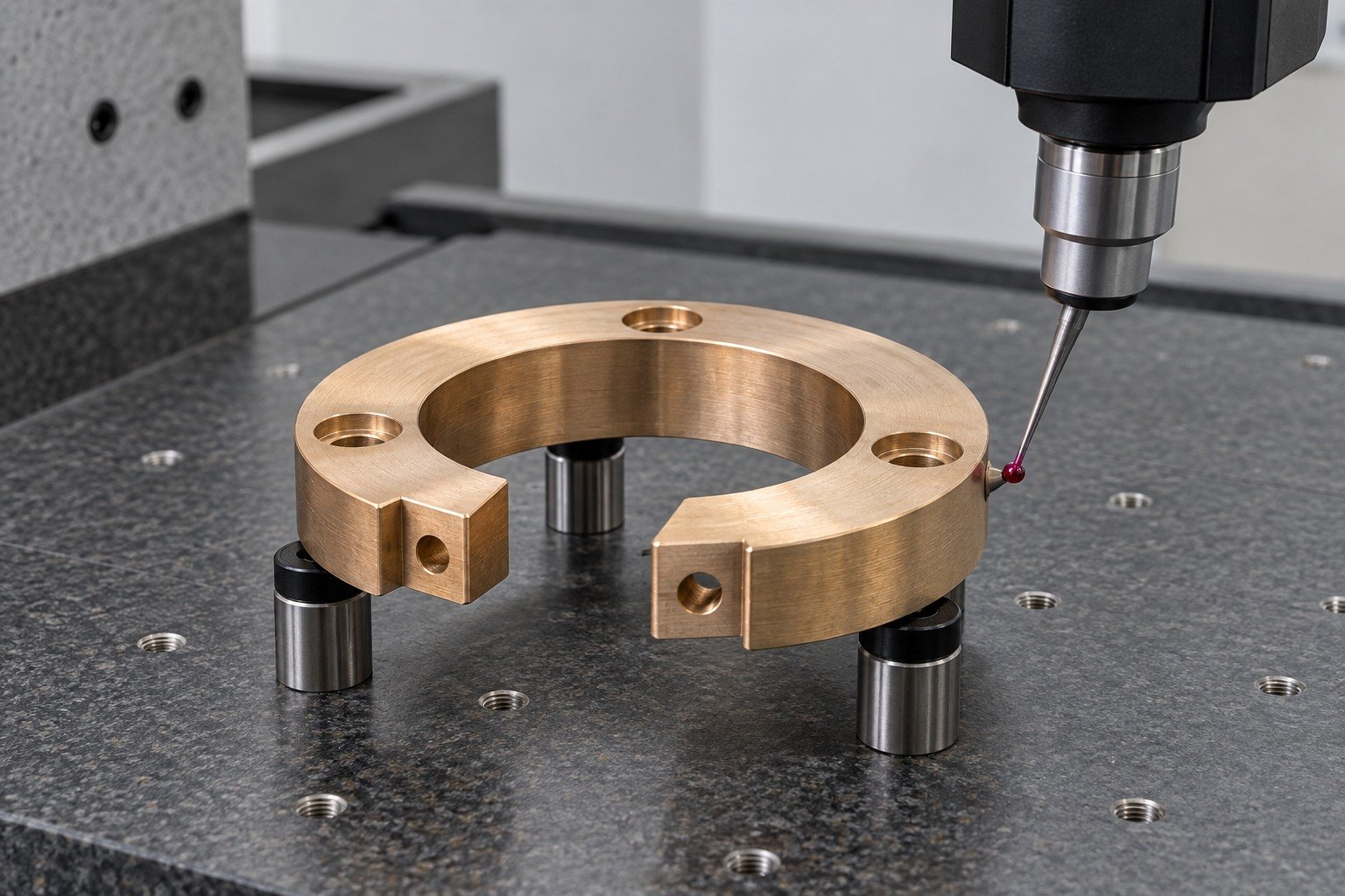
For your C172 beryllium copper machining review, confirm the actual drawing, supplied state and responsible process route. Operations, quantities and inspection scope remain subject to quotation review.
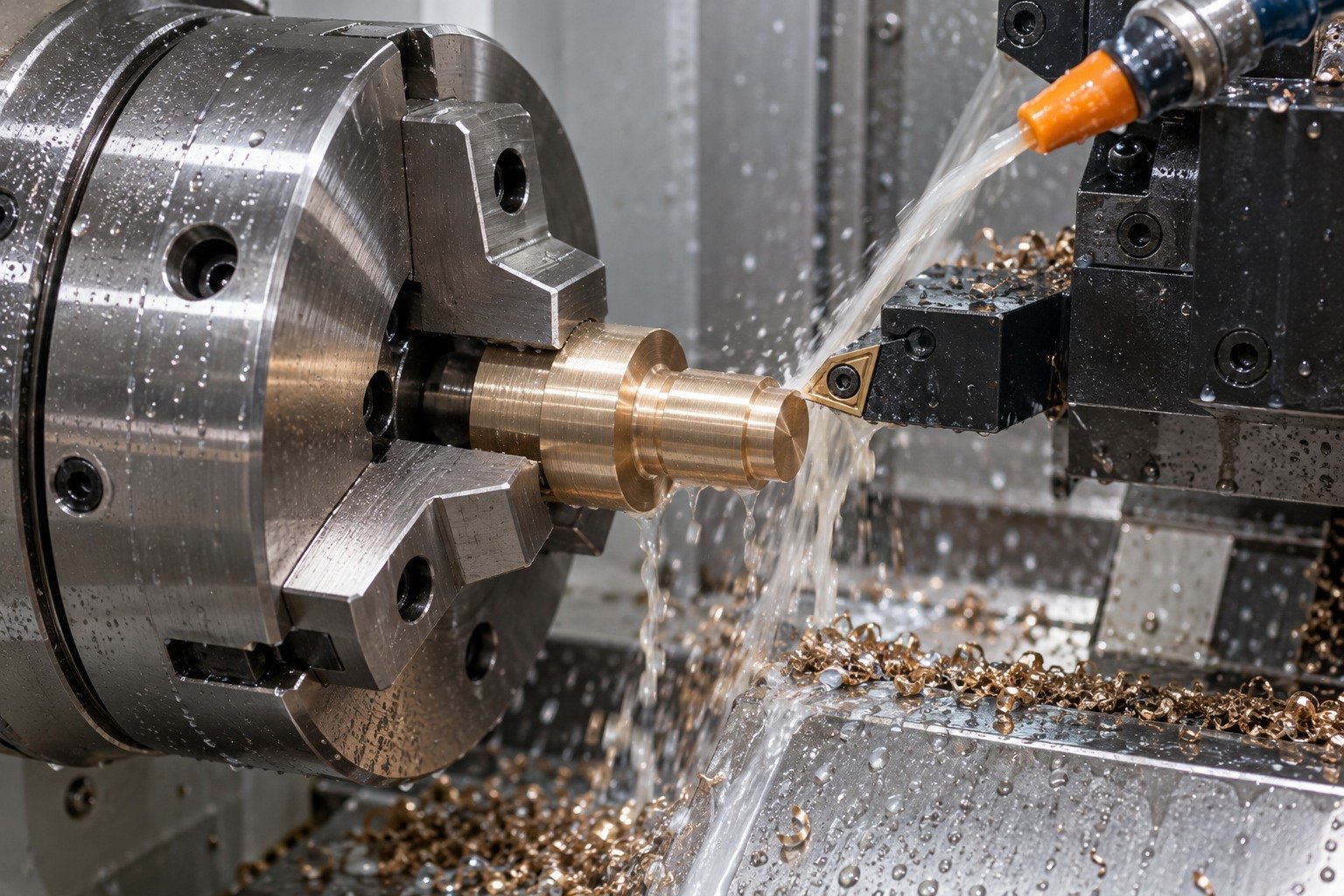
Review short supported contact shoulders, supplied state and the agreed material-specific route.
Explore the Process →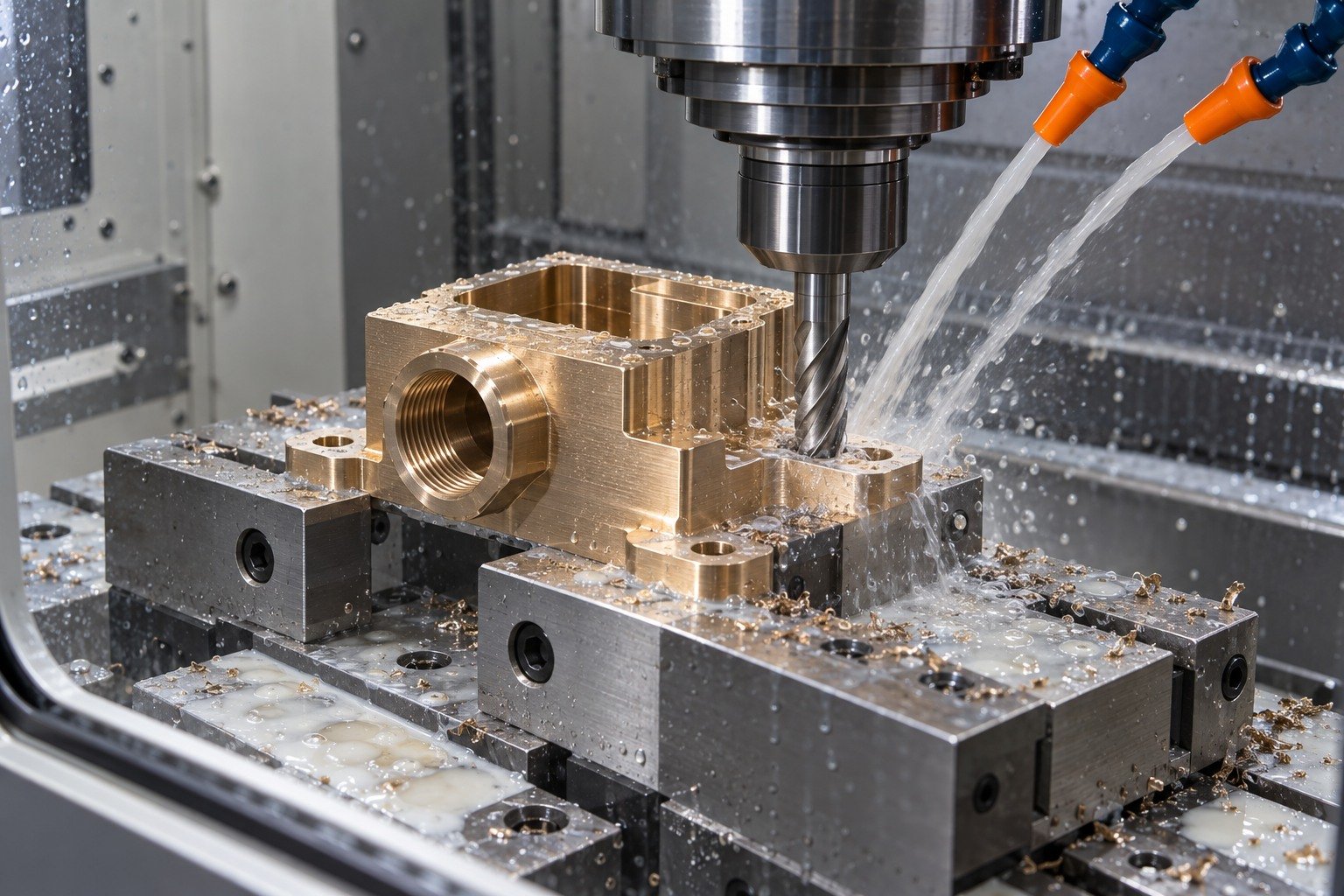
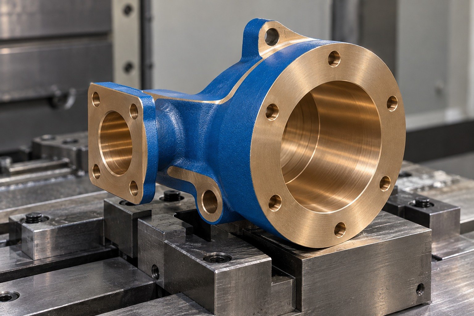
Define accessible connector pockets and mounting datums before the operation sequence.
Explore the Process →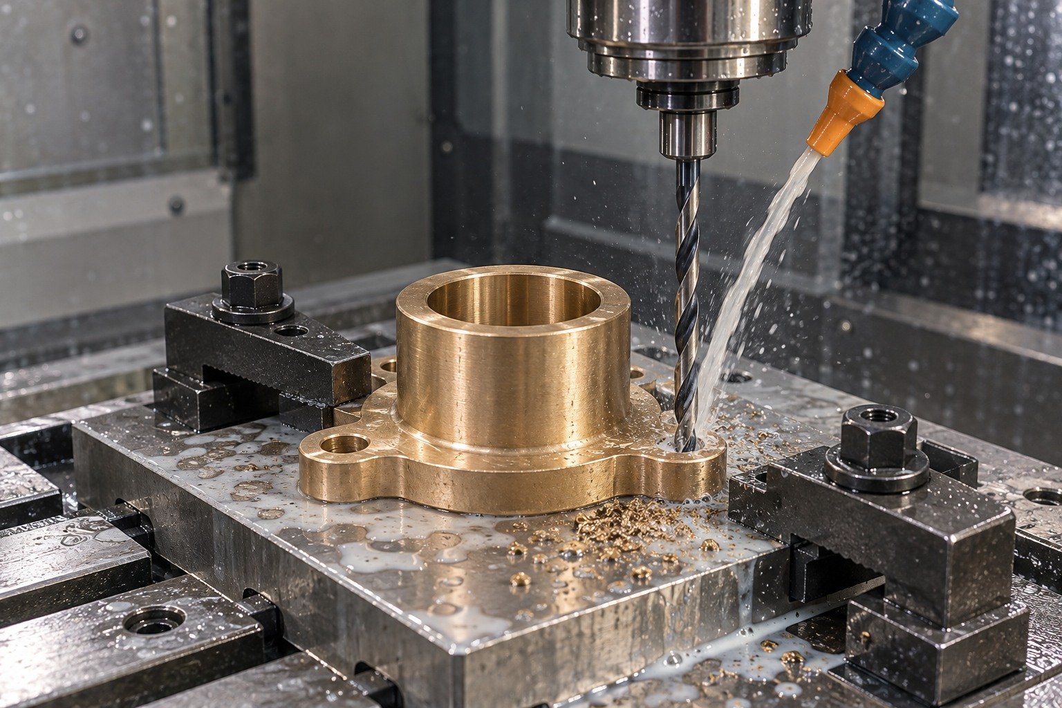
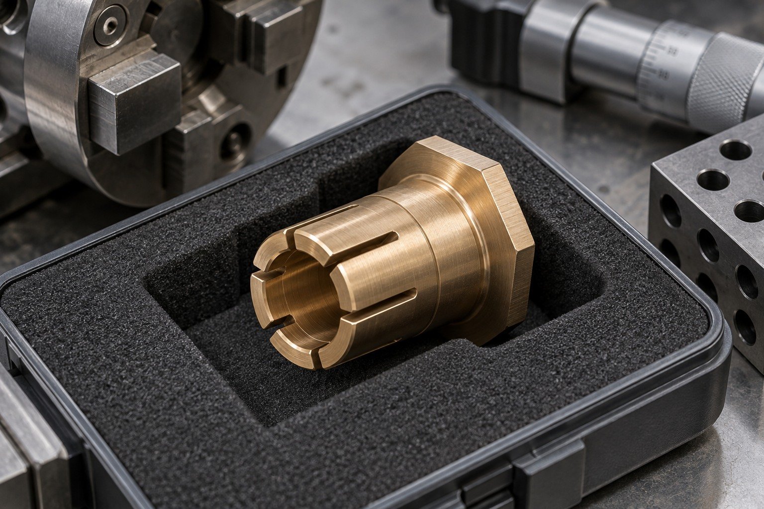
Review bore intersections, tool access and gauge requirements with the final edge limits.
Explore the Process →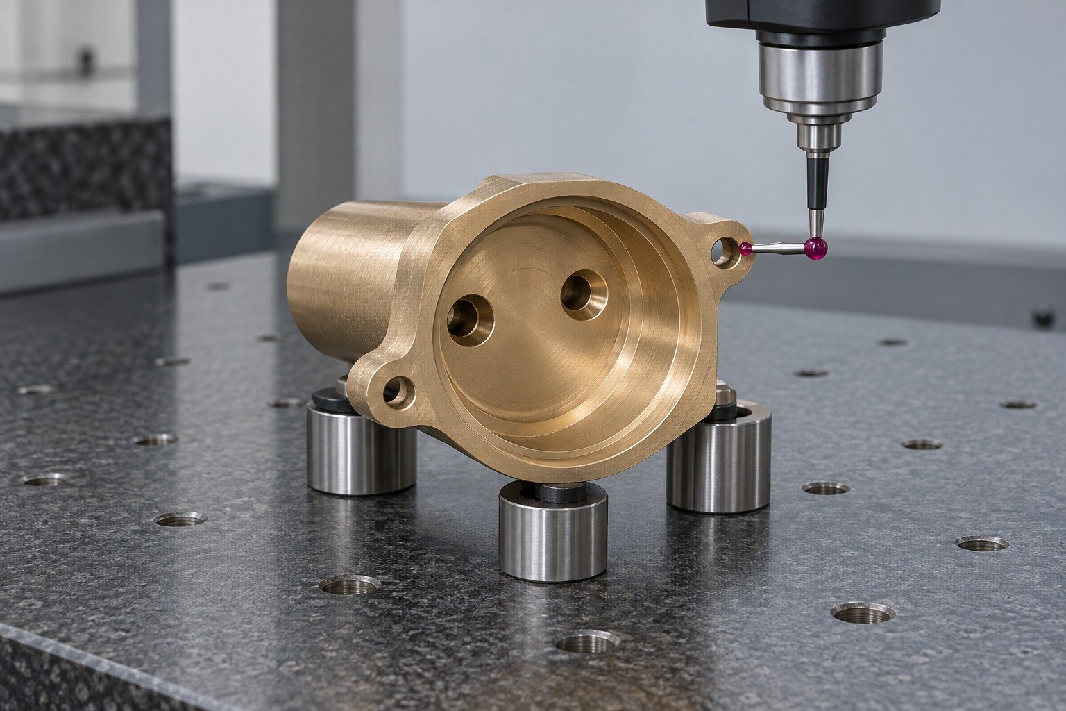
Check the finished contact and locating geometry after all specified operations.
Explore the Process →Resolve these six drawing decisions before repeating the manufacturing route.
Identify product form, exact temper and requested final condition. Confirm the material SDS and material-specific processing review before accepting stock or a machining route.
Show the working feature and allowed edge condition.
Agree stock, support and final surface.
Inspect the actual finished state.
Show bore intersections, slot-root radii, thread ends and measurement access. A clean outside surface does not establish acceptance inside a connector socket.
Show the working feature and allowed edge condition.
Agree stock, support and final surface.
Inspect the actual finished state.
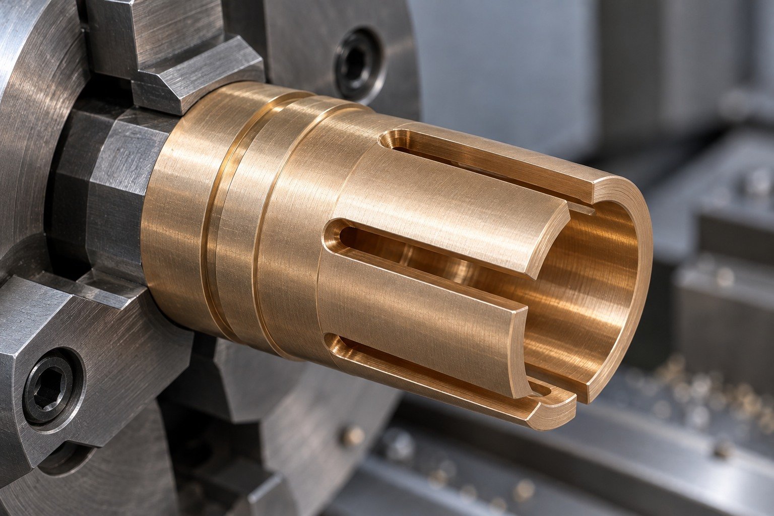
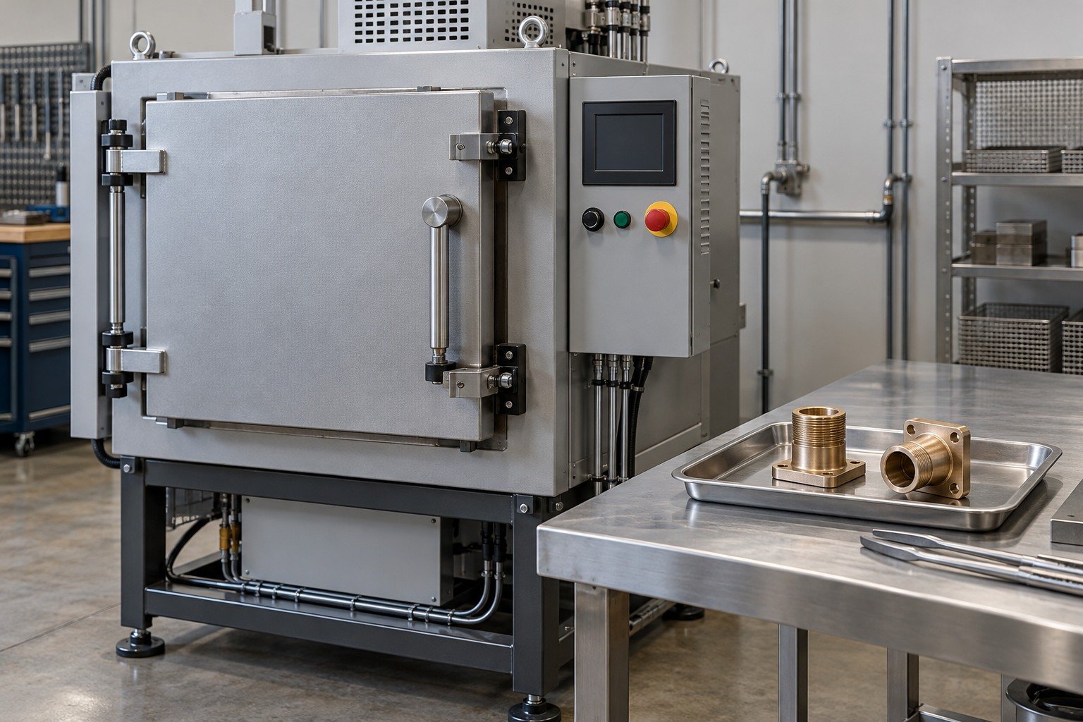
For C17200 machining before or after heat treatment, agree the actual sequence, final state and finishing allowance. Review C17200 heat treatment distortion against your locating datums; do not assume the as-cut part will retain every dimension.
Show the working feature and allowed edge condition.
Agree stock, support and final surface.
Inspect the actual finished state.
Define permitted edge breaks and reachable internal edges. Include deburring in the material-specific process review; agree how contact lands and slot roots will be protected and inspected.
Show the working feature and allowed edge condition.
Agree stock, support and final surface.
Inspect the actual finished state.
State the actual working face, roughness, masking and final protection. Review any plating or coating separately for the required contact function and final dimensions.
Show the working feature and allowed edge condition.
Agree stock, support and final surface.
Inspect the actual finished state.
Set critical dimensions from the actual assembly and material state. Review measurement access after the final route; no blanket tolerance or hardness applies to every C17200 part.
Show the working feature and allowed edge condition.
Agree stock, support and final surface.
Inspect the actual finished state.
| Comparison | Your purchasing decision |
|---|---|
| C17200 vs C17300 | C17300 is a lead-bearing machining variant; do not substitute without complete approval. |
| C17200 vs C17510 | Confirm exact chemistry, product form and required condition against the actual working requirement. |
| C17200 solution annealed vs aged | Retain the specified stock and final-state requirements; approve any sequence change. |
Reference data and a similar name do not approve substitution. Confirm the complete product standard and final acceptance.
Compare Copper, Brass & Bronze →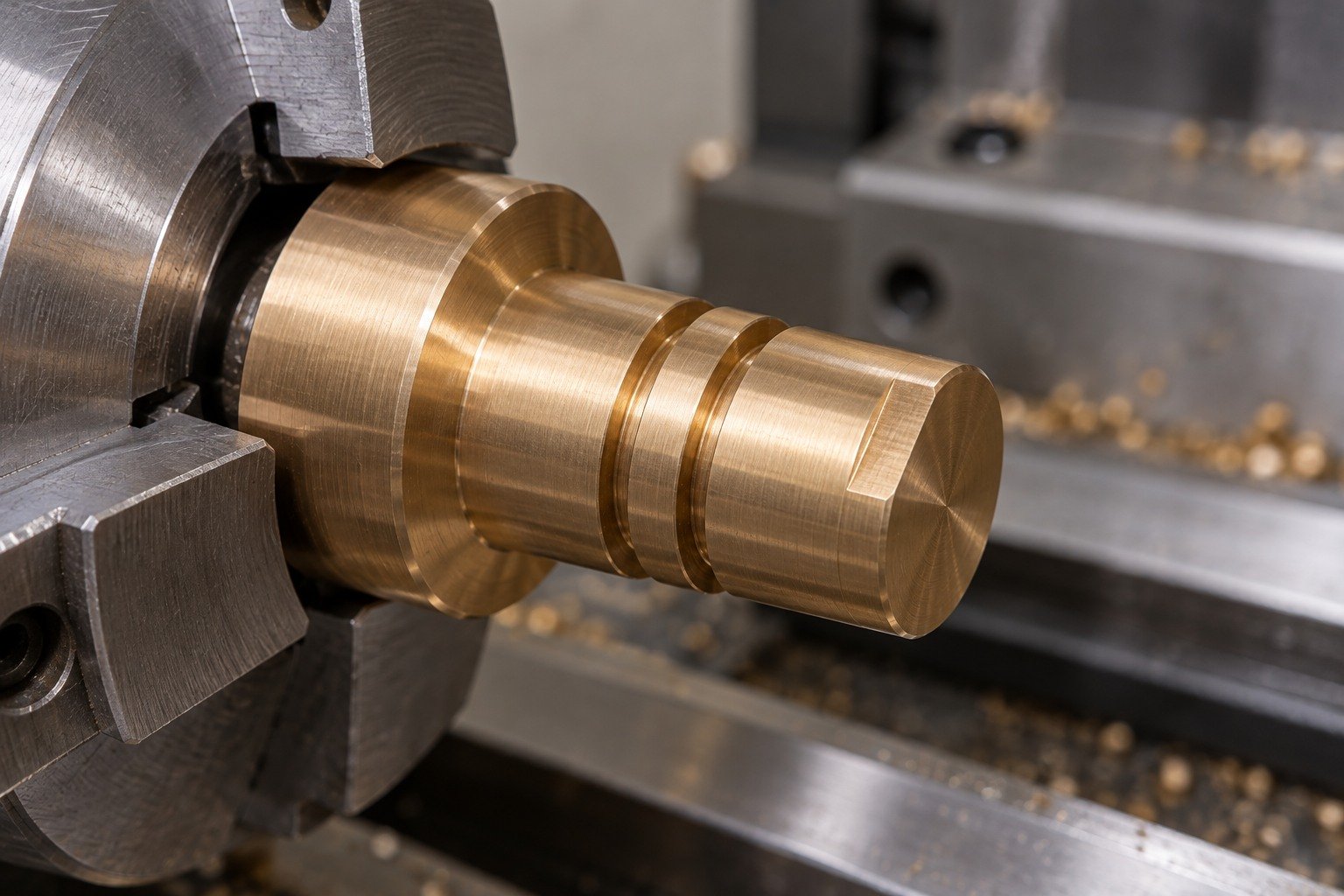

Illustrative appearances. Agree final contact surfaces, cleaning, masking and protection through the material-specific process review; no unspecified finish is promised.
Surface Finishing →Grade, product form, temper and lot.
Contact features and accepted edges.
Final fit, surface and records.
For your C17200 material certificate, state the exact product standard, lot identity, form and supplied temper. Confirm document scope and the material-specific route before ordering.
Sampling and evidence scope are agreed with your quote.
Quality Assurance →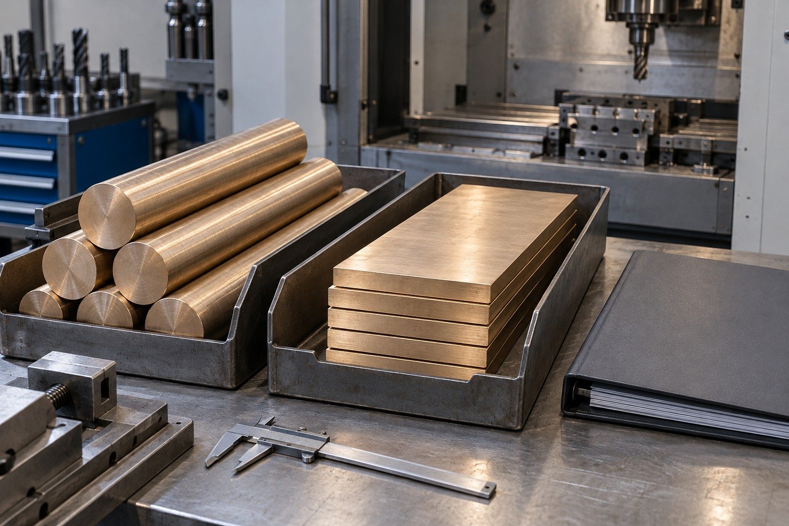
Use a controlled first sample to check connector fit, slot edges and final locating geometry. Confirm whether the sample represents the complete treatment and finishing route before repeat quantities.
Sampling and evidence scope are agreed with your quote.
Quality Assurance →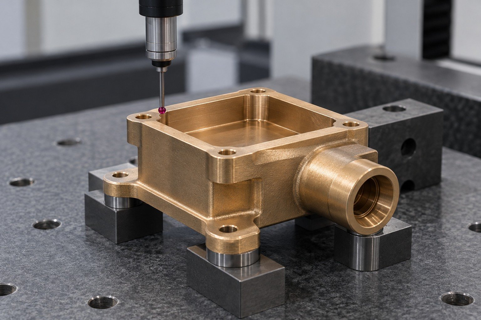
For C17200 dimensional inspection, measure the agreed features after the complete route. State the exact hardness method and acceptance separately when C17200 hardness after aging is required.
Sampling and evidence scope are agreed with your quote.
Quality Assurance →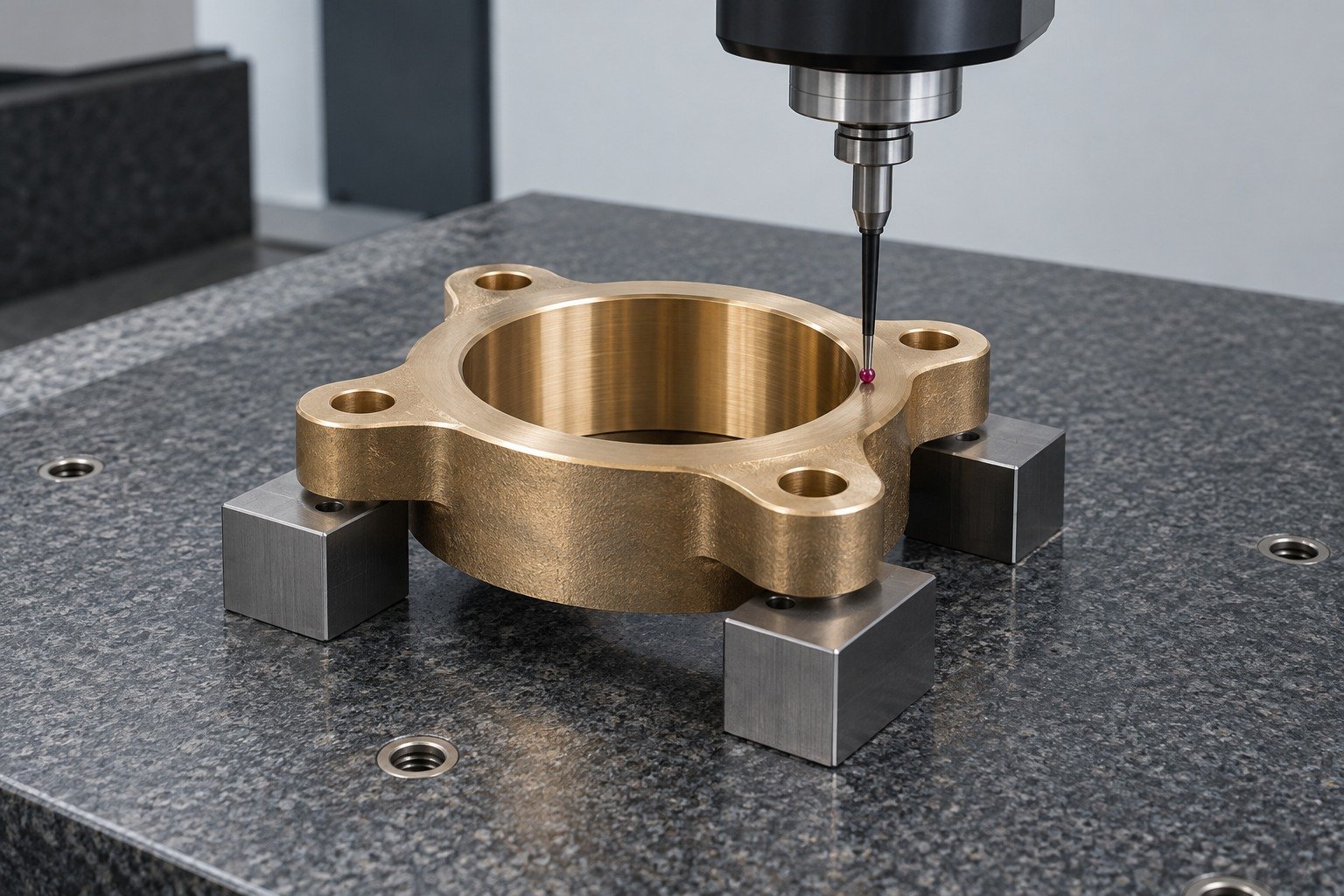
Agree identification, separate protection for working faces and the requested receiving records. Material identity, final dimensions and any specified treatment evidence answer different questions.
Sampling and evidence scope are agreed with your quote.
Quality Assurance →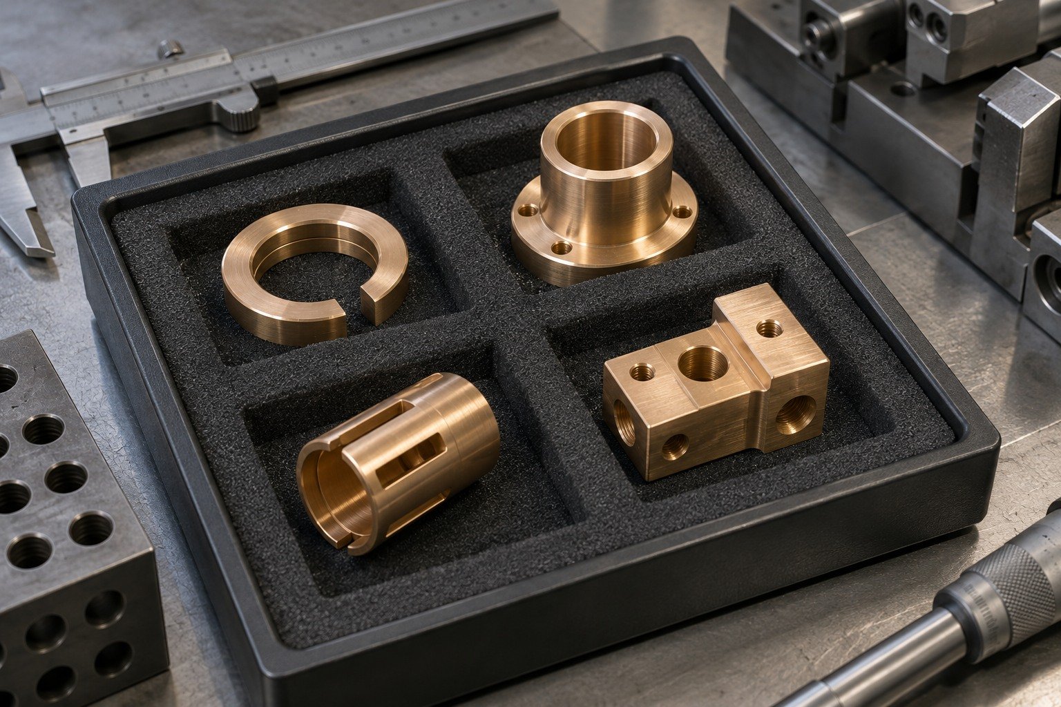

Connect China manufacturing with Dallas-area coordination for drawing review, sample decisions and delivery requirements.
C17300 is a lead-bearing copper-beryllium machining variant. Compare the actual chemistry, product form, state and application restrictions before approving any change; a higher published machining rating is not a substitute for the complete requirement.
Specify the exact alloy, product standard, supplied condition and required final performance. These are distinct copper-beryllium grades; do not infer interchangeability from a general BeCu label.
Identify both the supplied temper and the required finished condition at inquiry. Agree the operation sequence, treatment responsibility and remaining allowance before accepting a route.
Connect tool access, supplied state, treatment sequence and final dimensions. Agree a first sample that represents the full route, then inspect critical locating and contact features in that final state.
Review geometry, retained stock, prior condition and the specified treatment route with the responsible processor. Reserve an agreed finishing allowance and verify final datums rather than assuming a universal shrinkage value.
The result depends on the exact product form, supplied condition and treatment. Specify the final hardness method, acceptance range and evidence with your order; this page does not guarantee one value for every part.
Your C17200 machining quote depends on material form and state, setups, feature access, treatment and finish, material-specific processing requirements, quantities and evidence. Compare quotations against the same drawing revision and complete final route.
For your C172 beryllium copper machining inquiry, supply the controlled drawing, exact material and state, final contact fits, accepted edges, treatment responsibility and receiving records. Confirm the current SDS and material-specific process review before production.





