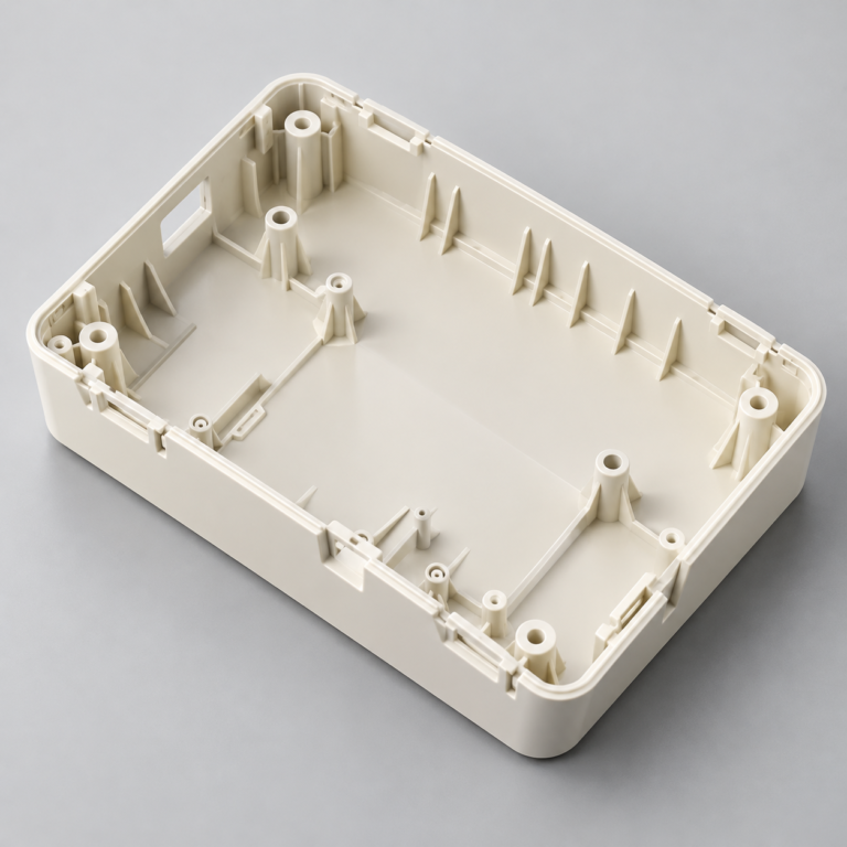
Injection Molding
Tooling and molding for your repeat plastic parts.
From prototype to production, coordinated manufacturing solutions for your custom parts.
View All Services →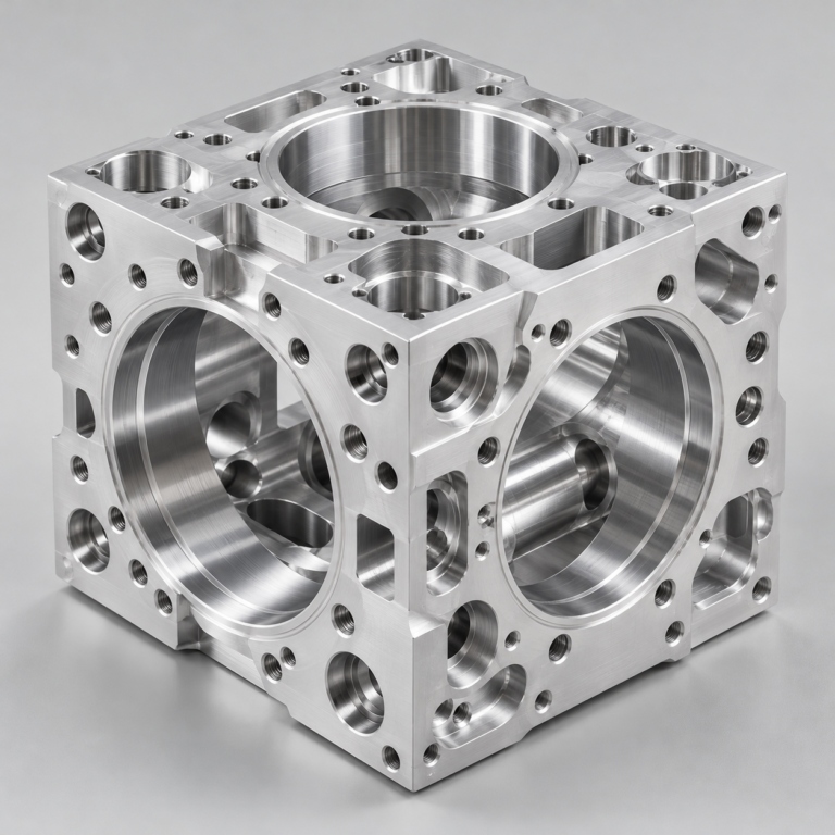
Precision parts for your tight tolerances and complex geometry.
Tooling and molding for your repeat plastic parts.
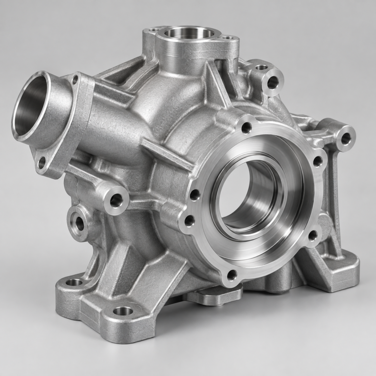
Metal casting options for your part and production volume.
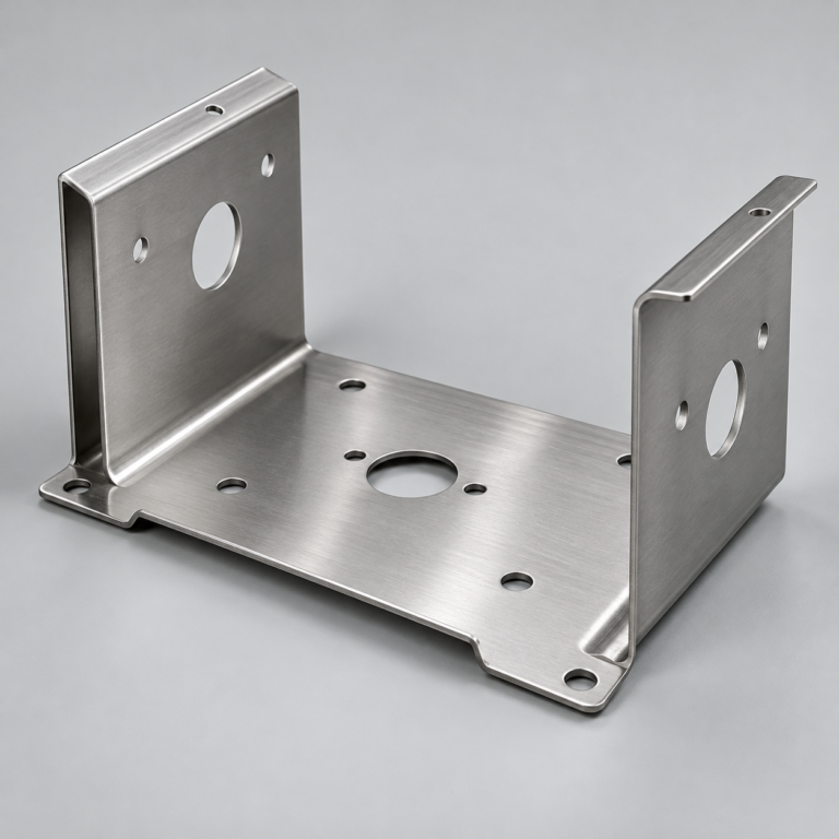
Cutting, forming and welding for your fabricated parts.
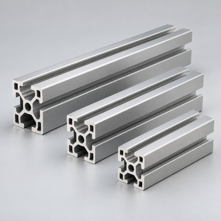
Custom profiles for your section, length and finish requirements.
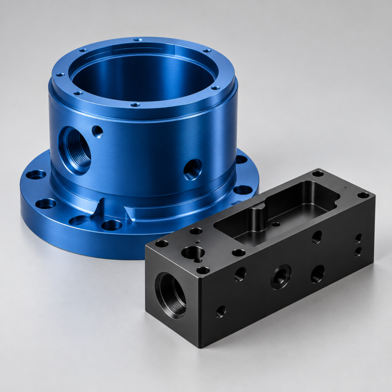
Finishes for your appearance, corrosion and wear requirements.
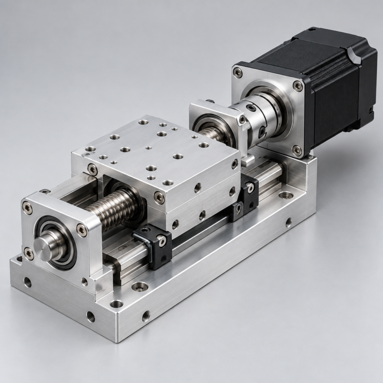
Sub-assemblies and final builds for your production program.
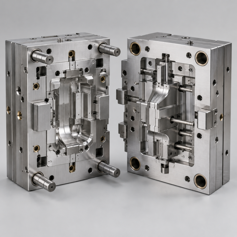
Production tooling built around your process and volume.
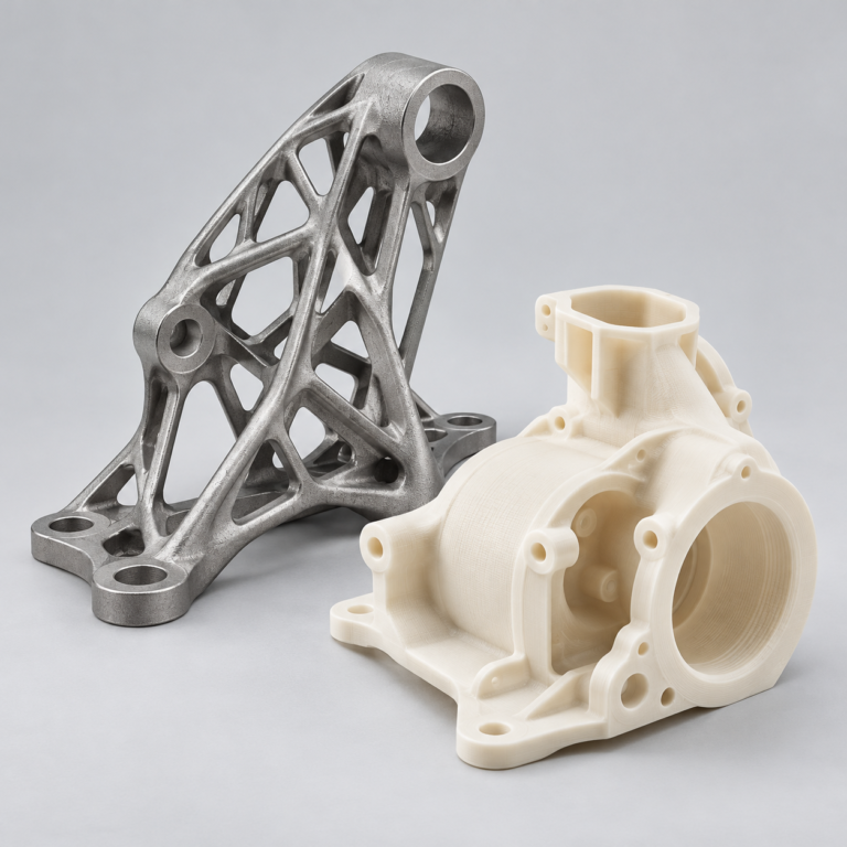
Prototype parts to check fit, function and design.
Choose air- or liquid-cooling components around your thermal and mechanical requirements.
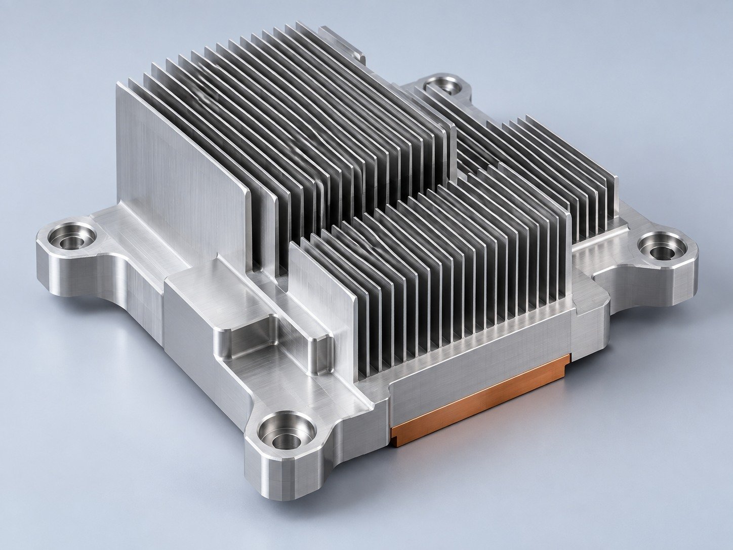
Manufacturing support for your cold plates, manifolds and cooling assemblies.
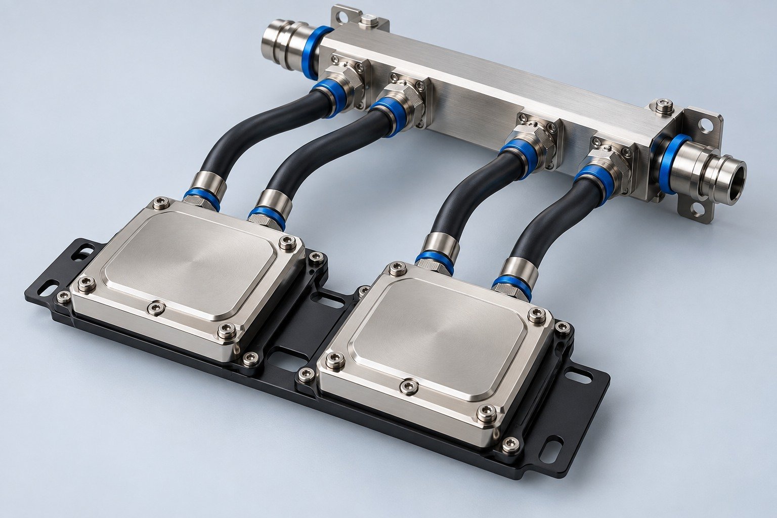
Find components for your power electronics, energy, laser and telecom application.
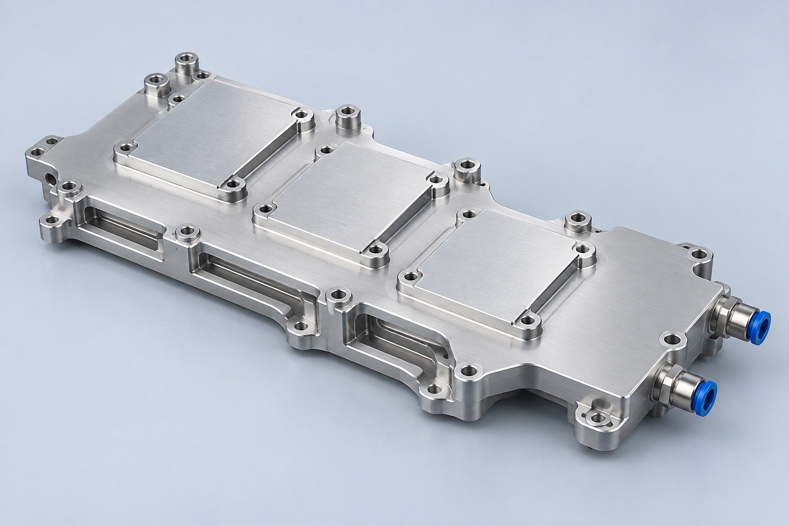
Components for your electronic systems.
Start with your functional and quality requirements.
Build around your operating environment.
From prototype to production, review material performance, manufacturability and cost for your part.
Review grade, temper and finish for your metal parts.
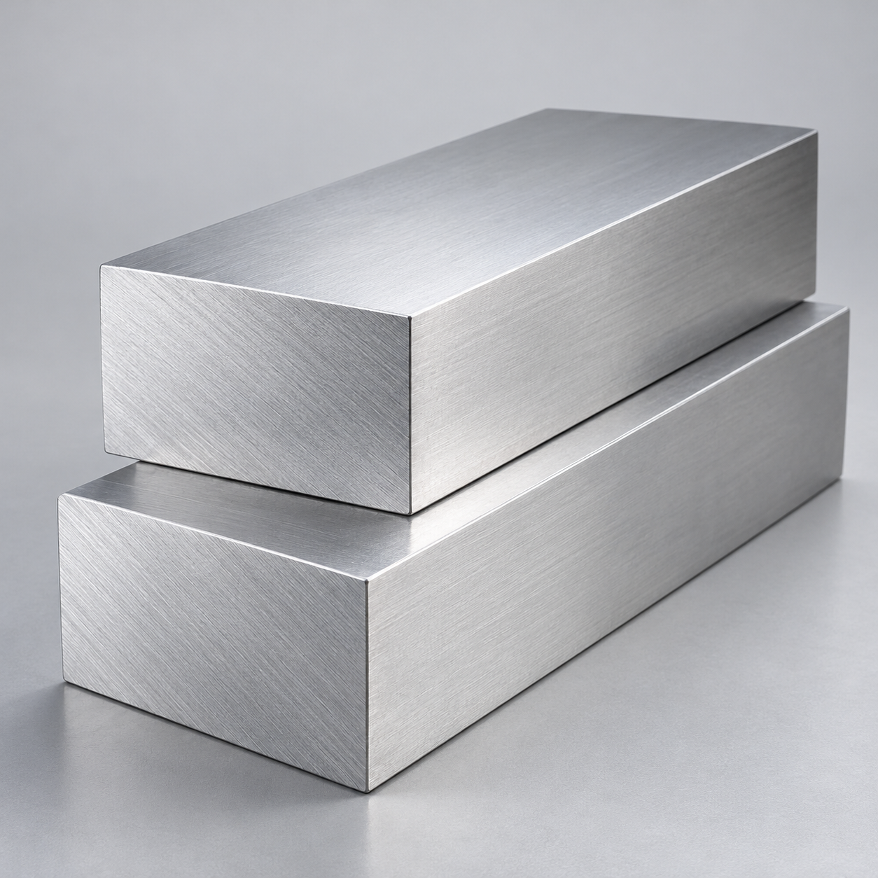 AluminumStrength, weight and machining›
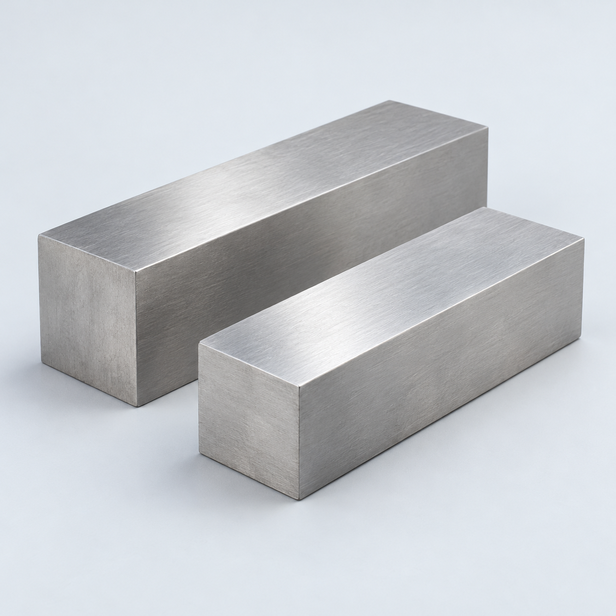 Stainless SteelCorrosion and finish requirements›
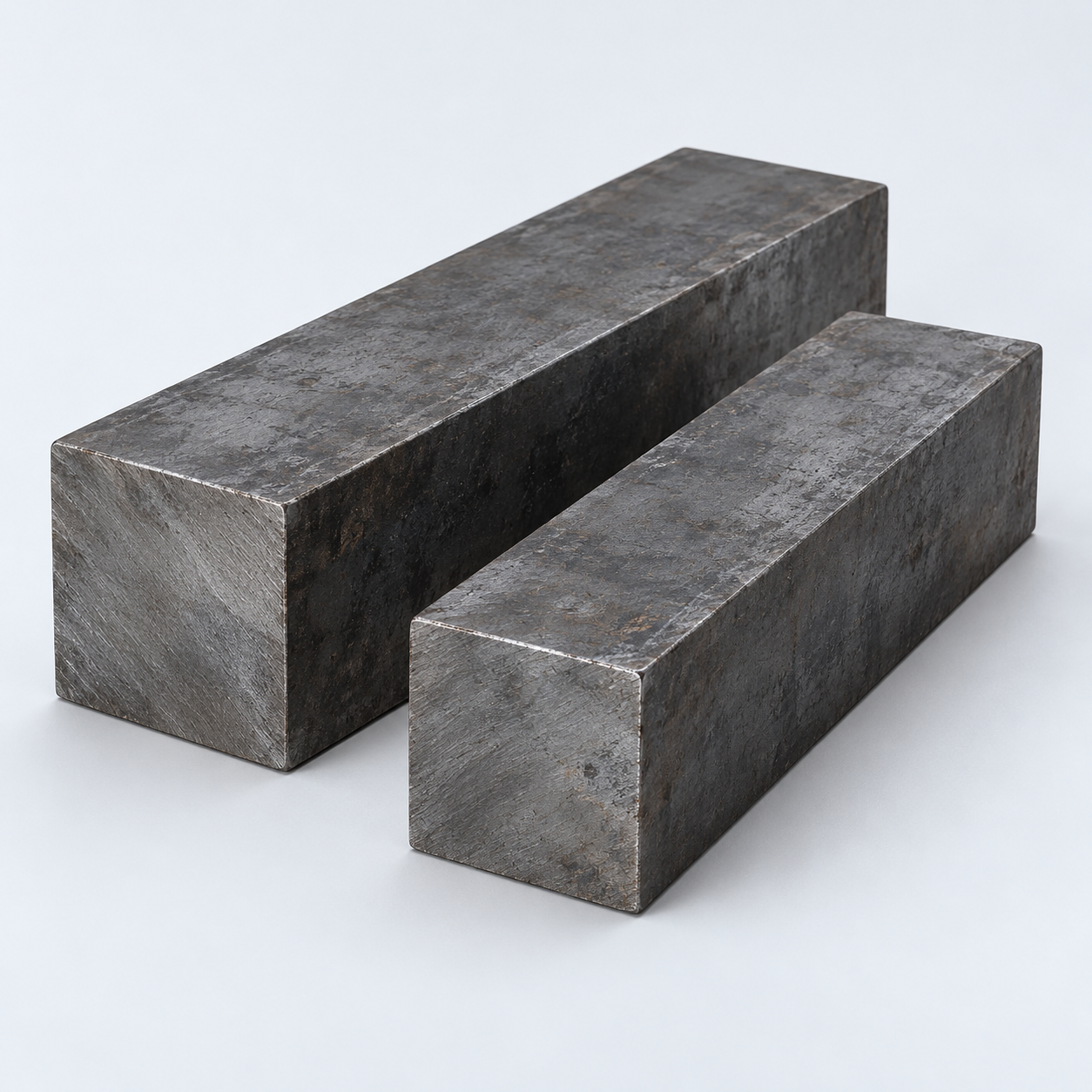 Carbon & Alloy SteelDiscuss grade and heat treatment›
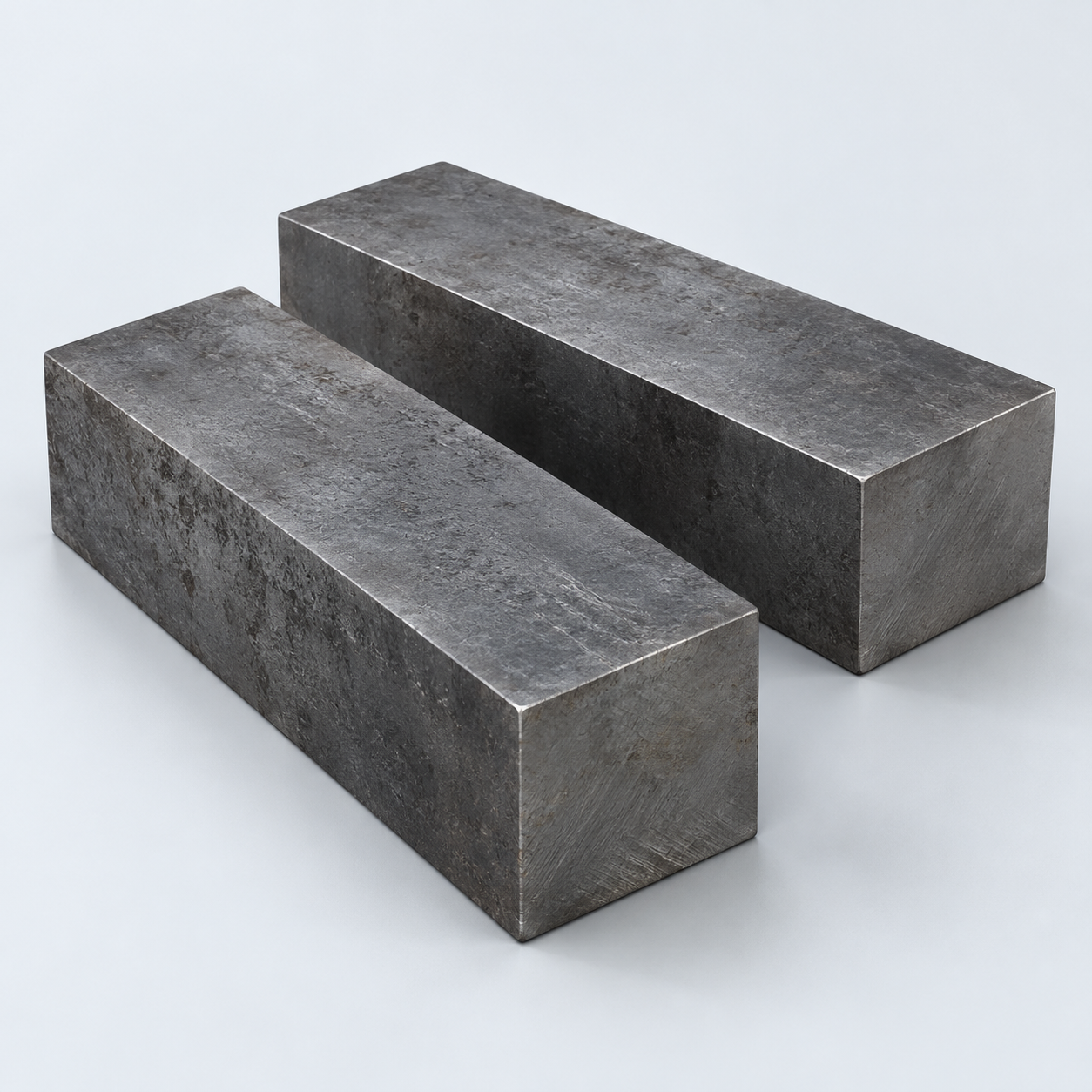 Tool SteelDiscuss tooling and wear needs›
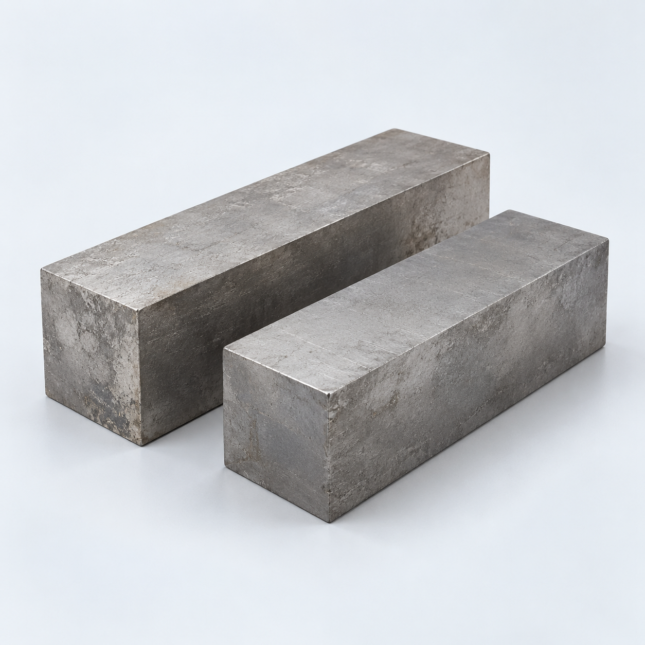 TitaniumReview grade and part geometry›
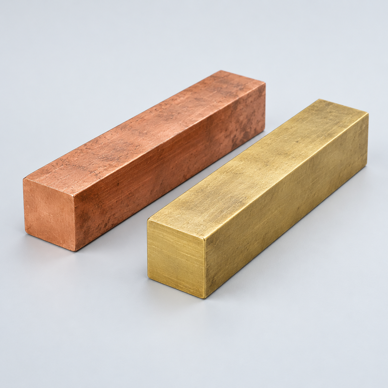 Copper & BrassDiscuss conductivity and machining›
Match your polymer to function, process and environment.
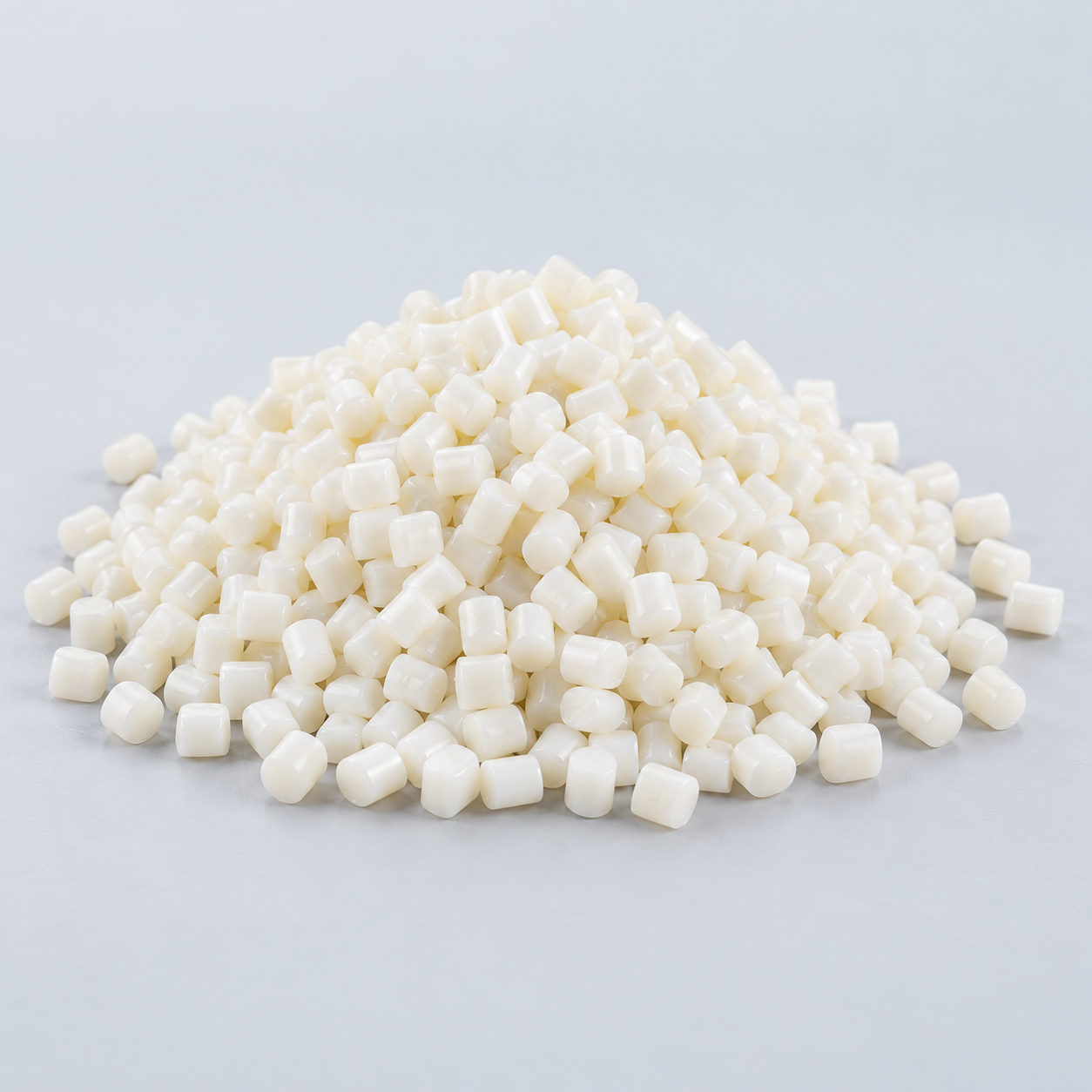 ABSReview enclosure and molding needs›
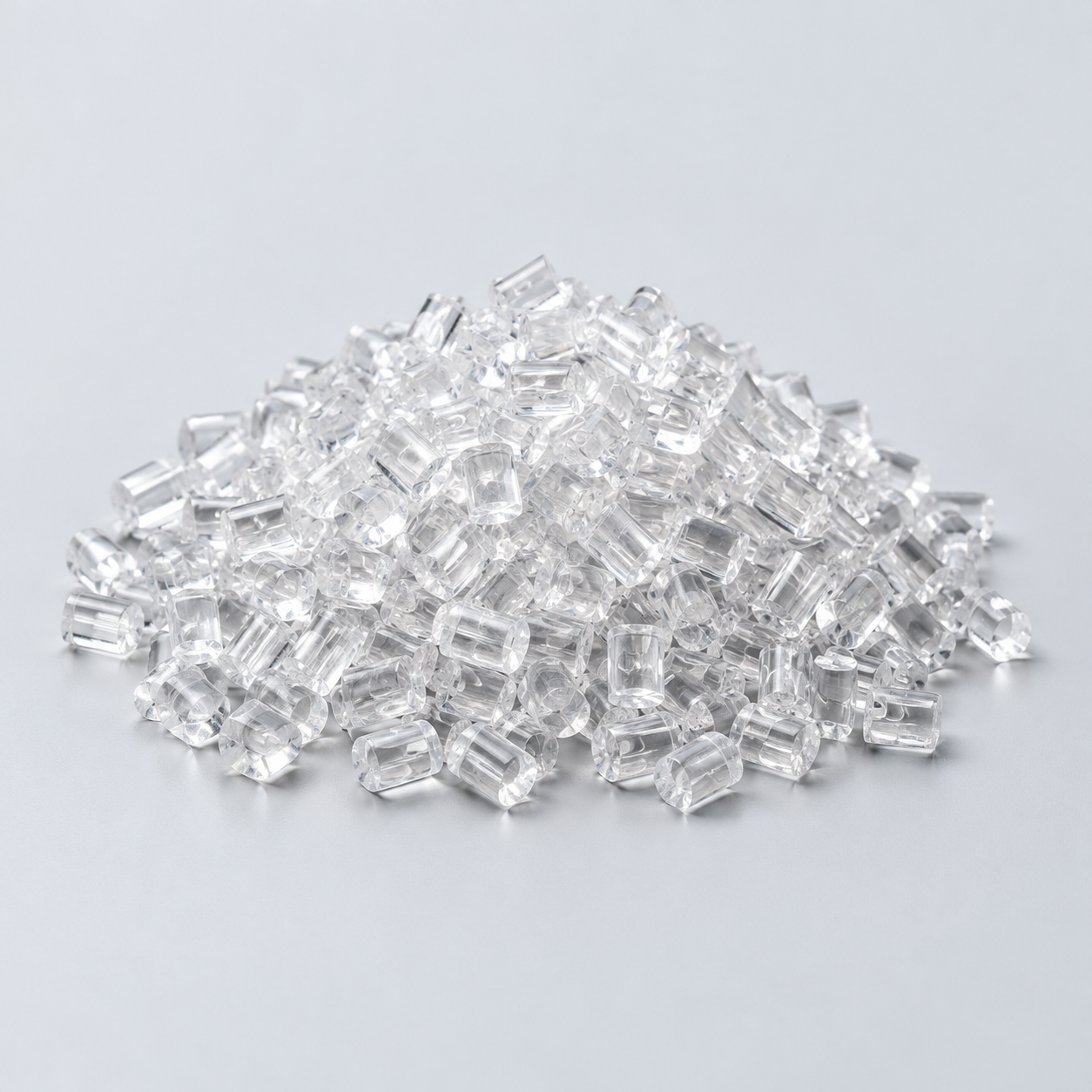 Polycarbonate (PC)Discuss clarity and impact needs›
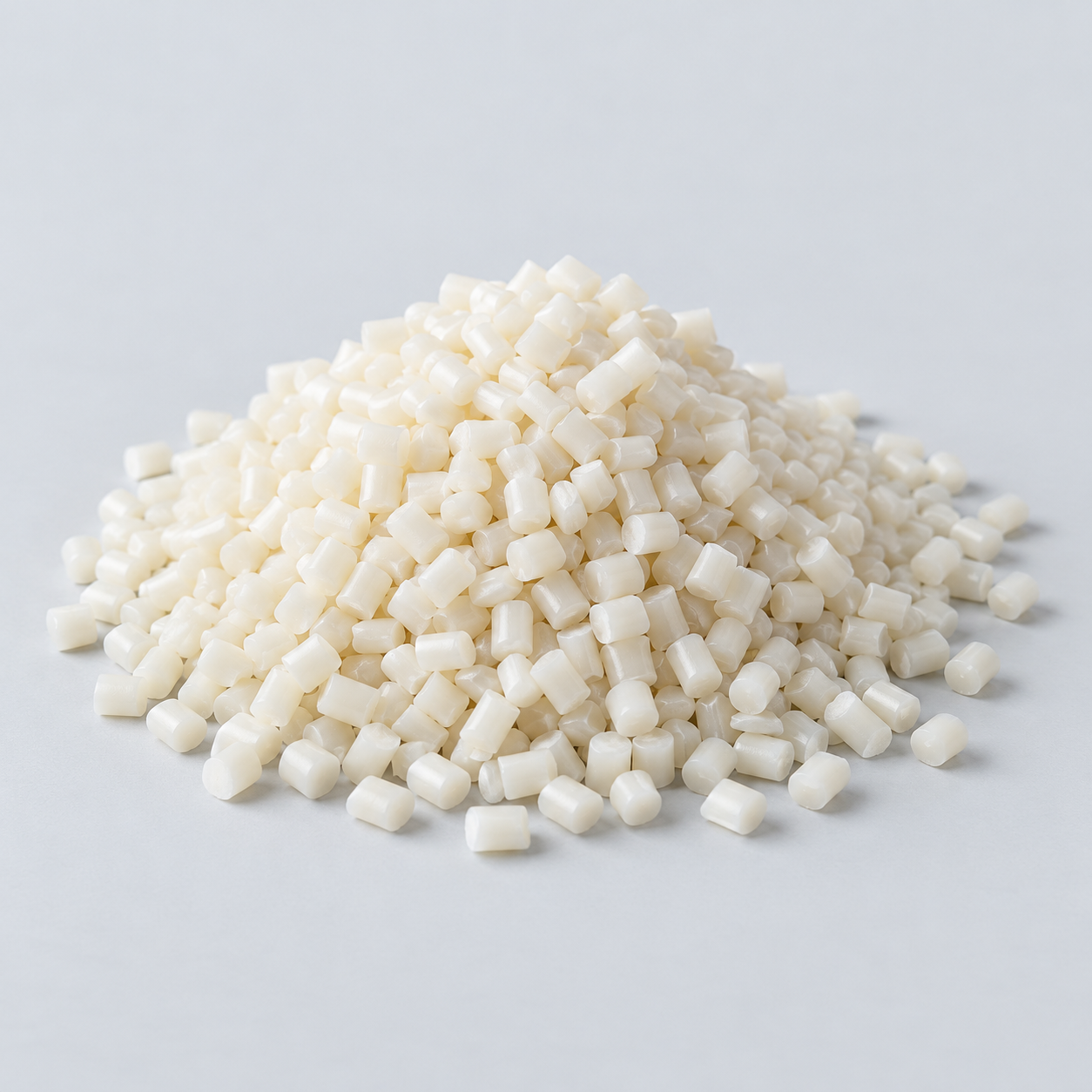 Nylon (PA)Review moisture and wear conditions›
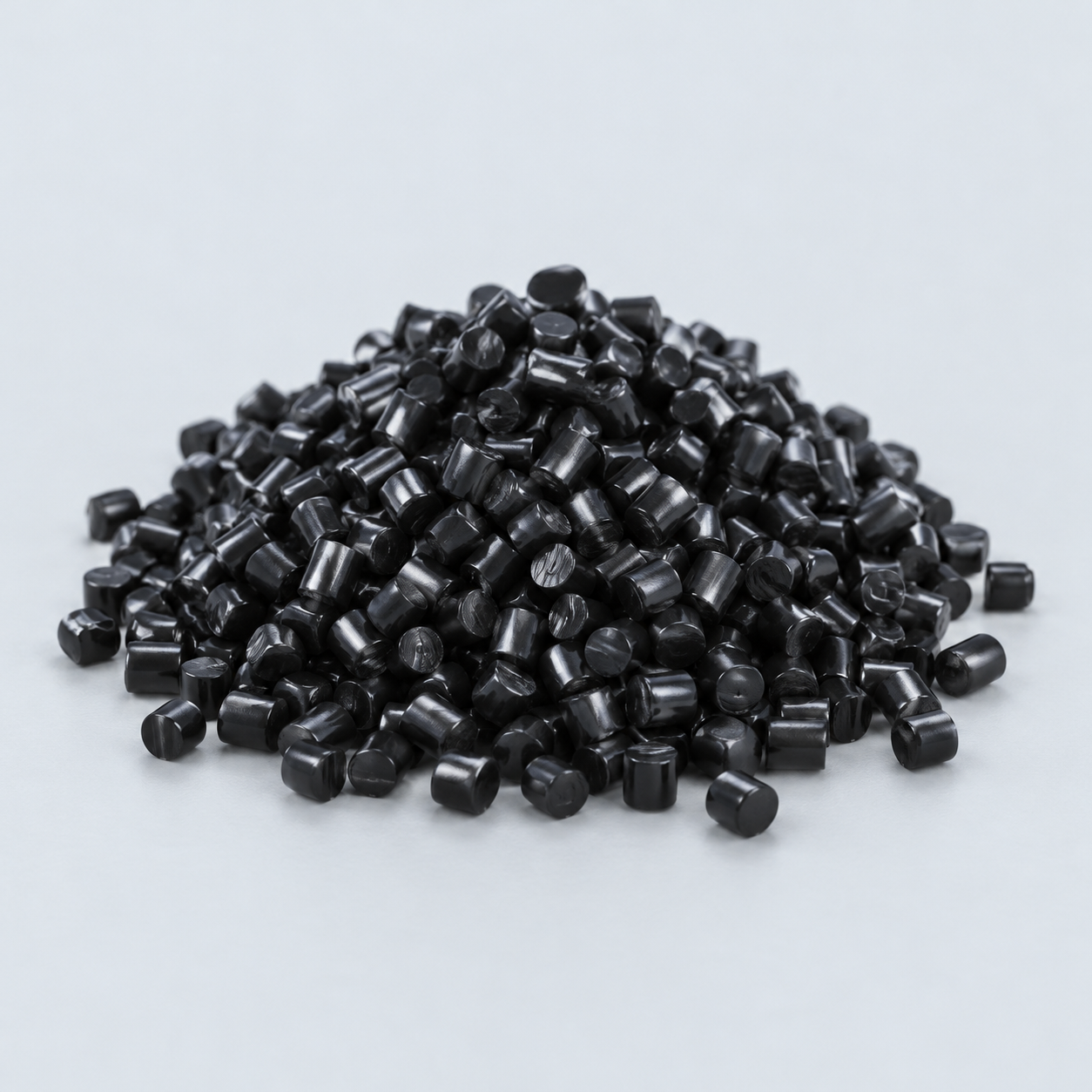 POM / AcetalReview fit and sliding features›
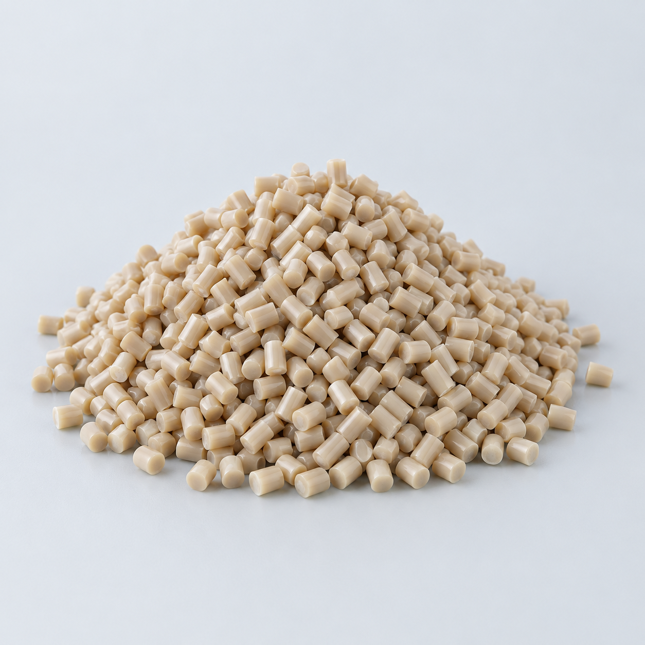 PEEKDiscuss operating conditions›
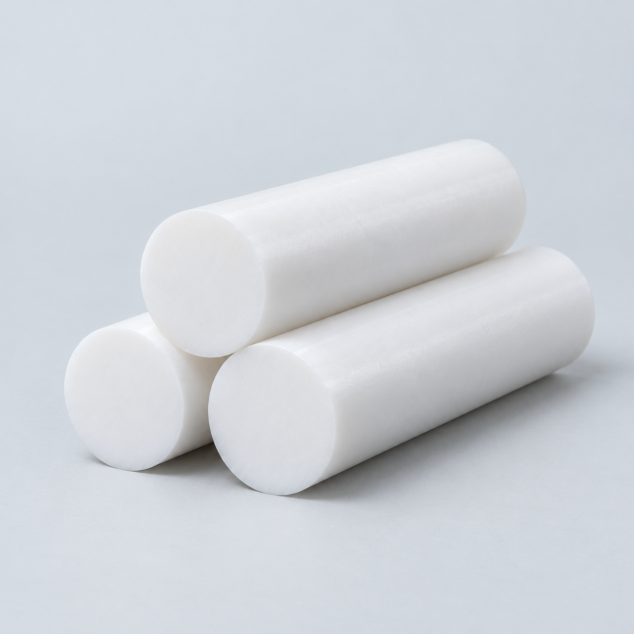 PTFEReview friction and chemical exposure›
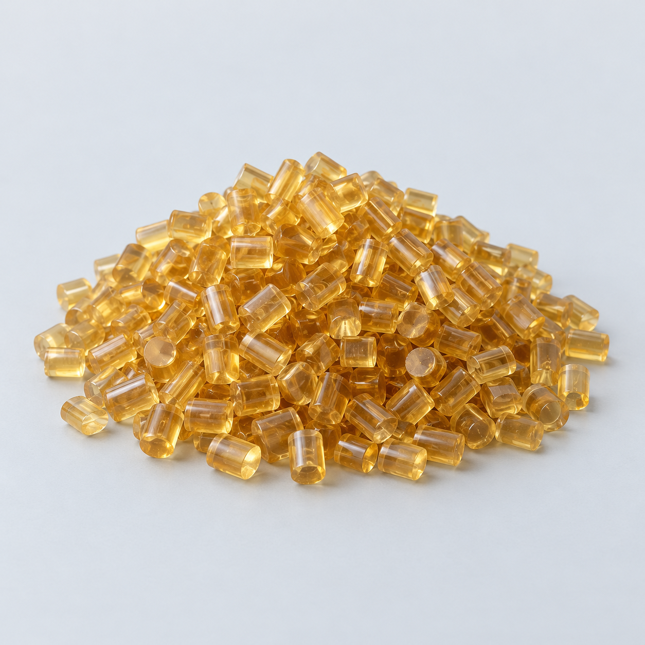 ULTEM / PEIDiscuss thermal and electrical needs›
Confirm grade availability and application requirements.
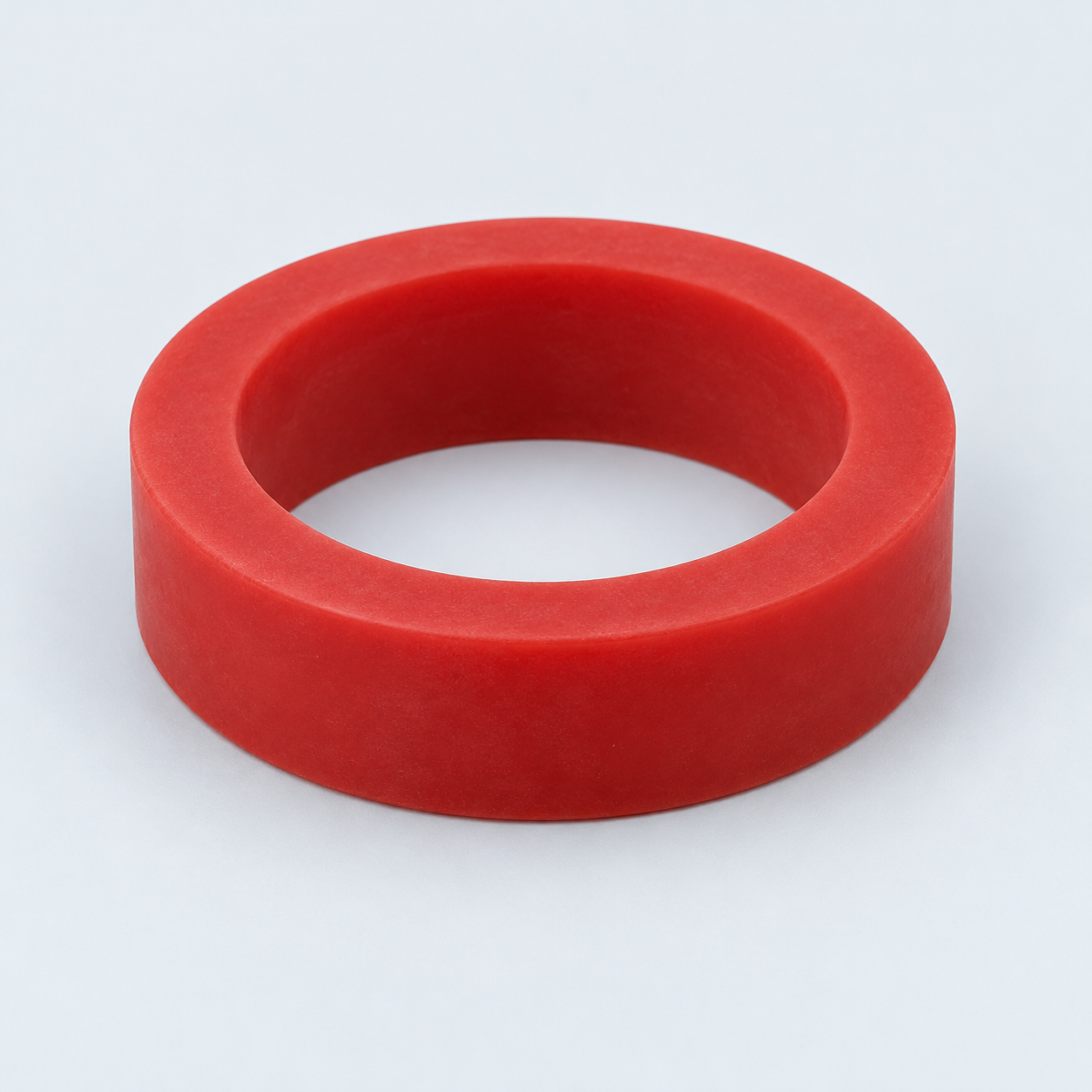 Silicone / LSRDiscuss flexible component needs›
 TPU / TPEReview flexibility and processing›
 EPDMReview weathering and chemical exposure.›
 NBRReview oil and fuel exposure.›
 FKMReview temperature and chemical exposure.›
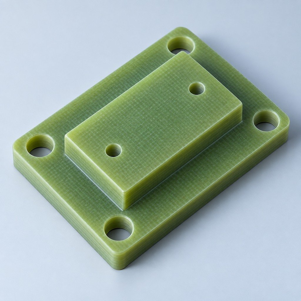 G10 / FR4Review insulation and laminate needs›
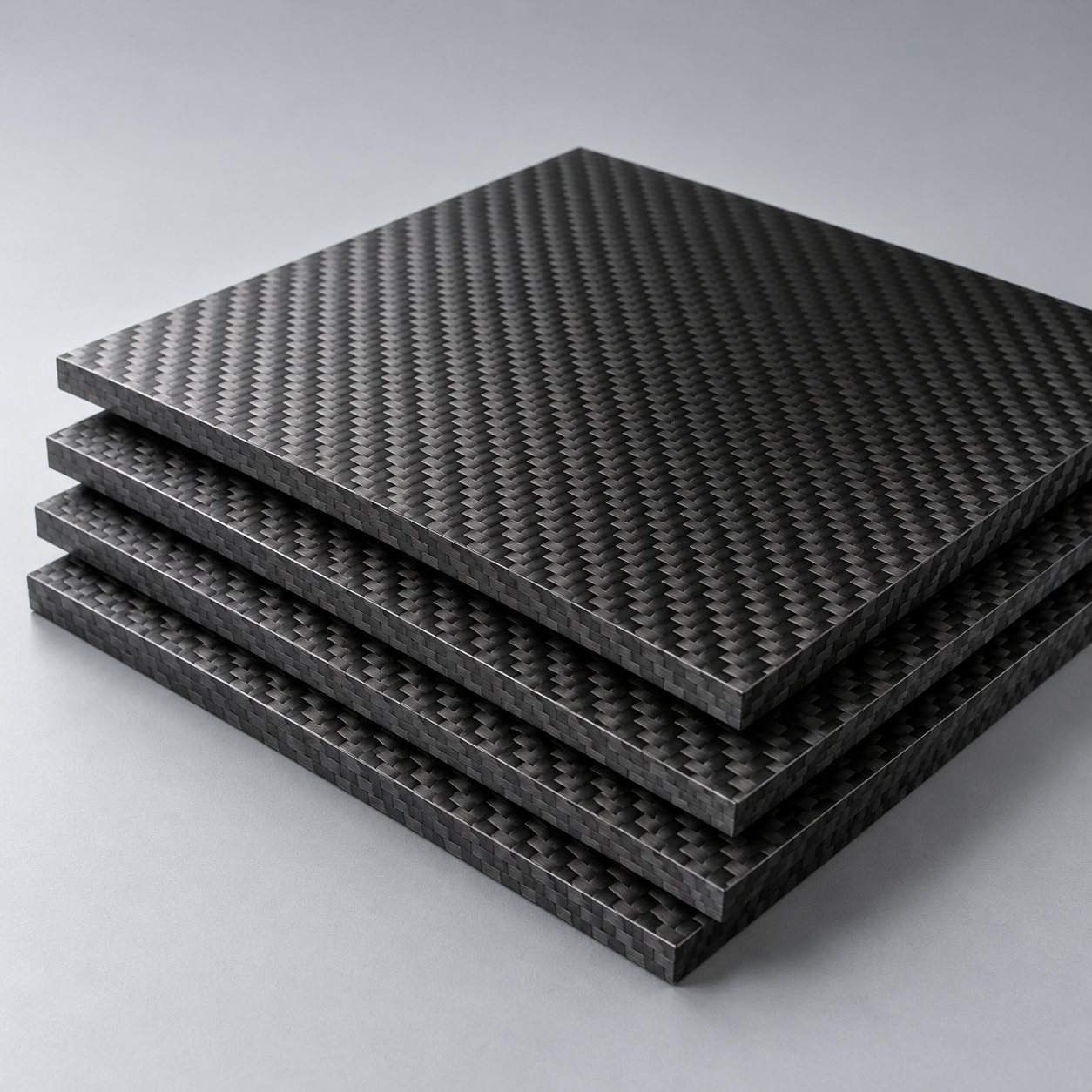 CompositesReview stiffness, weight and laminate.›Customer-Specified MaterialsConfirm your grade and requirements.›Other Specialty MaterialsDiscuss your application and grade.›
Practical guidance for your part geometry and material decisions.
Prepare your process, budget and sourcing questions.
Build your knowledge before production.
Learn who we are and how we operate.
Find our U.S. support team or start a conversation.
YOUR ALLOY. YOUR FINISH. YOUR FINISHED FIT.
Review your alloy, finish callout and critical interfaces together. Plan masking, color samples and final inspection before your aluminum parts enter finishing.
Start with 1 controlled drawing + your alloy, quantity and finish specification. Standalone finishing or machining-plus-finishing scope is confirmed for your project.
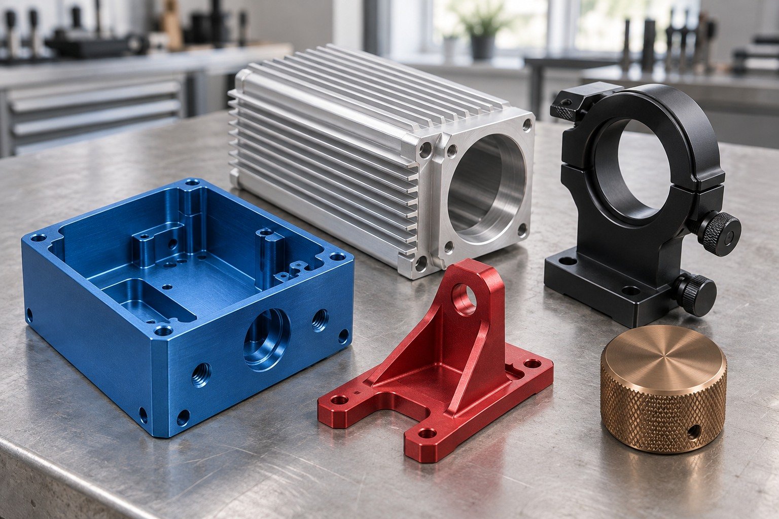
Specify your substrate
Confirm type and requirements
Mark masks and final fits
Agree color and acceptance
Dallas-area project support
Define the finished condition so quotes and samples answer the same requirements.
Grade, temper and original surface.
Type, thickness and seal requirements.
Bores, threads and contact zones.
Color, texture and visible faces.
Quantity, records and delivery scope.
Select your part, then review the finish decisions that affect its use. Route and supply scope are confirmed for your drawing.
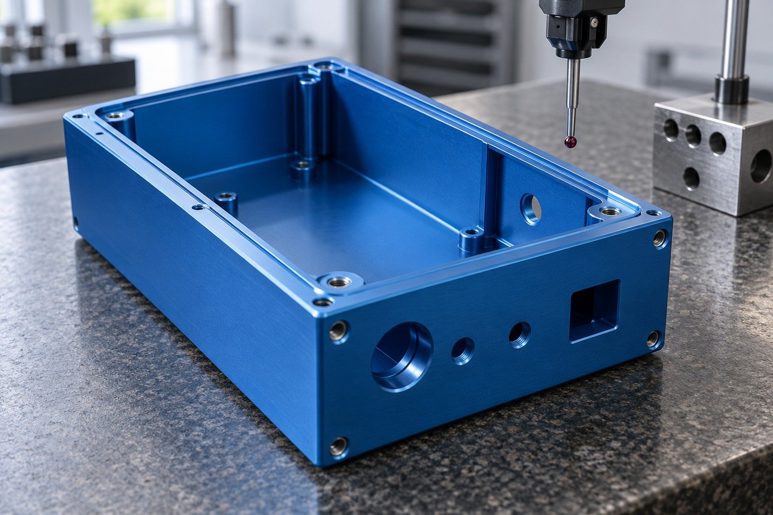
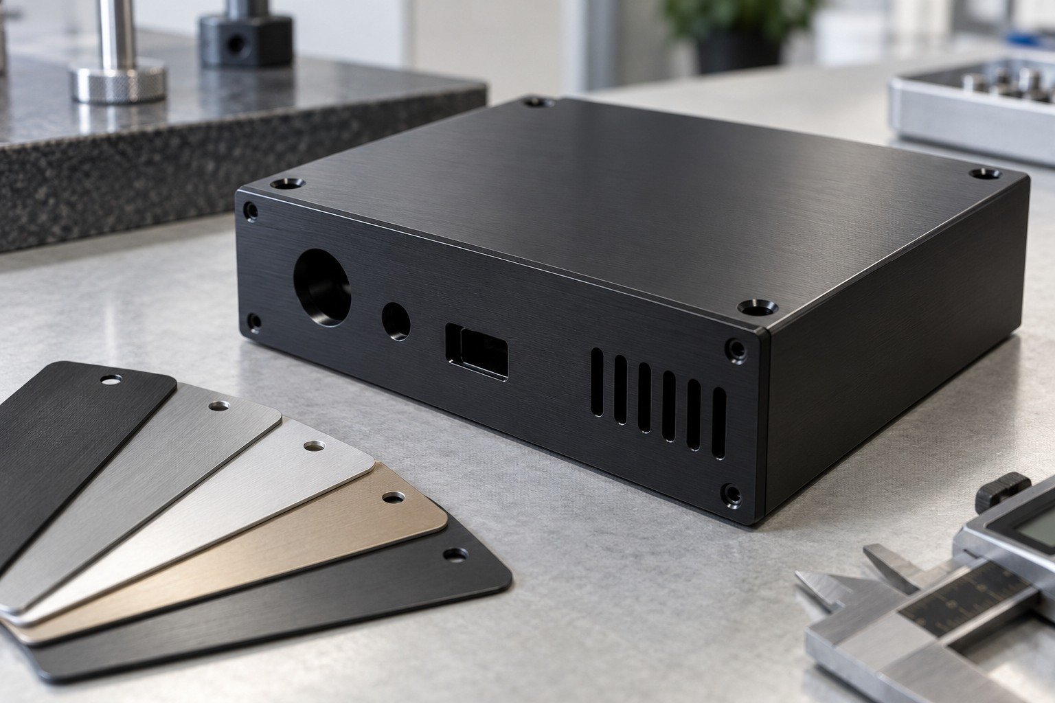
When anodizing aluminum enclosures, identify the cover seat, cosmetic faces and any electrically conductive contacts.
| Your interfaces | Cover seats, fasteners and grounding. |
|---|---|
| Your appearance | Visible exterior faces and inner pockets. |
| Your approval | Assembled fit after finishing. |
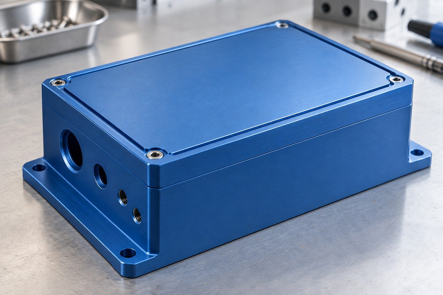
Confirm the enclosure alloy and surface preparation; different material lots or welded areas can affect appearance.
| Your substrate | Exact alloy, temper and incoming surface. |
|---|---|
| Your callout | Type, specification/revision, thickness and seal. |
| Your sample | Texture, color and agreed acceptance limits. |
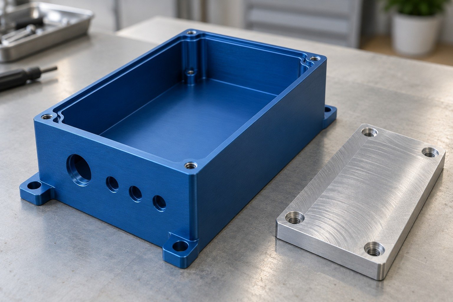
Separate cosmetic faces from allowable hidden contact marks and conductive grounding zones.
| Your drawing | Cover seats, fasteners and grounding. |
|---|---|
| Your boundaries | Visible exterior faces and inner pockets. |
| Your agreement | Rack contacts, mask transitions and final inspection. |
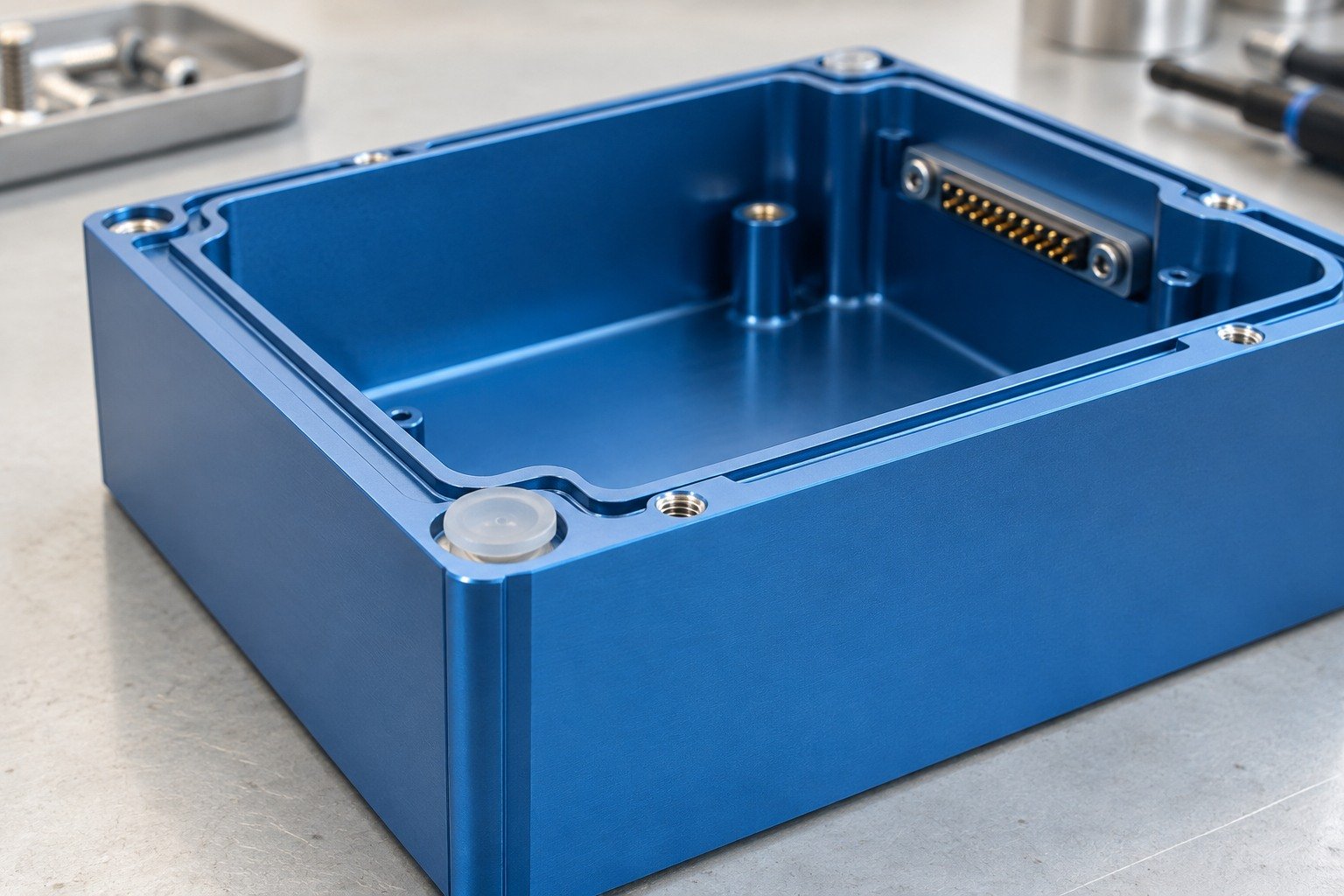
Check the assembled cover and contacts as well as the external color sample.
| Your final fit | Assembled fit after finishing. |
|---|---|
| Your method | Datums, gauges and agreed measurement stage. |
| Your evidence | Sample revision, finish records and acceptance results. |
For anodizing aluminum heat sinks, review mounting and thermal-contact surfaces separately from visible fins.
| Your interfaces | Base flatness, fin access and mounting. |
|---|---|
| Your appearance | Thermal interfaces and contact areas. |
| Your approval | Appearance and specified functional checks. |
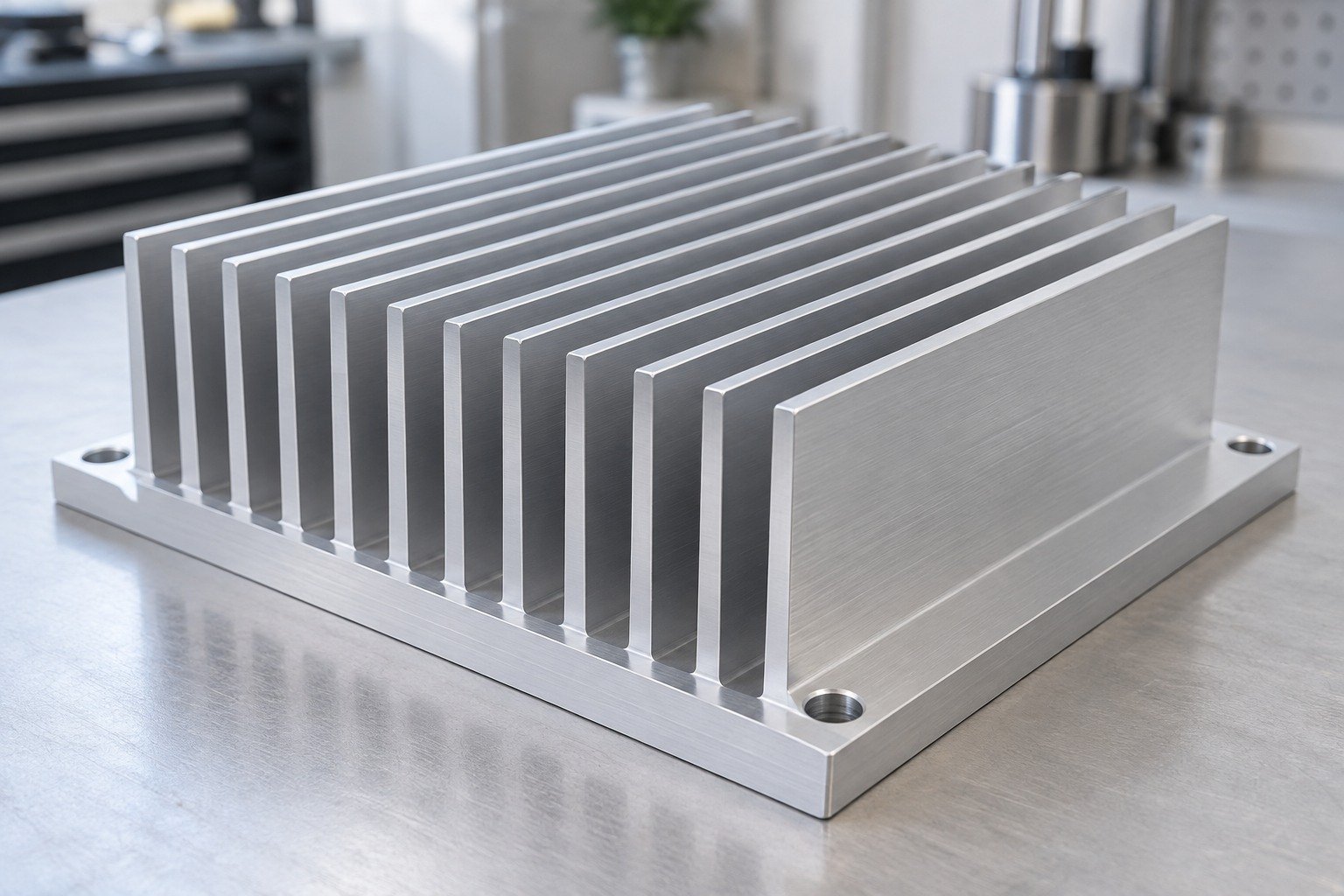
Review the extrusion alloy and original surface, then define finish type, thickness and any thermal-contact exclusions.
| Your substrate | Exact alloy, temper and incoming surface. |
|---|---|
| Your callout | Type, specification/revision, thickness and seal. |
| Your sample | Texture, color and agreed acceptance limits. |
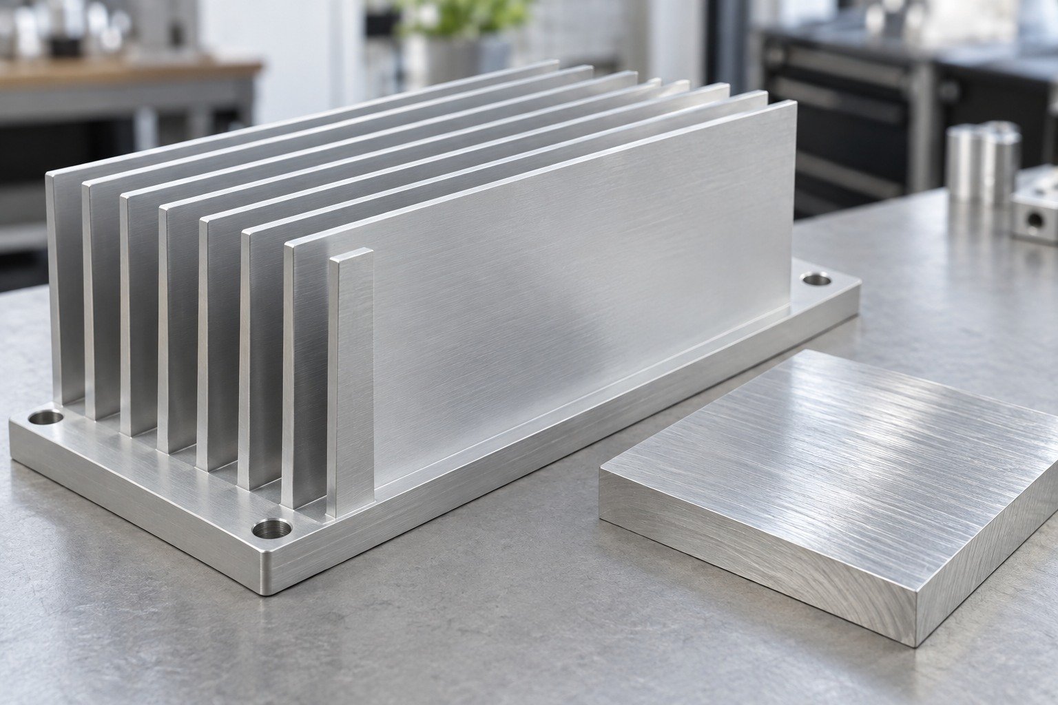
Mark base contacts, plugged holes and any areas excluded from the treatment.
| Your drawing | Base flatness, fin access and mounting. |
|---|---|
| Your boundaries | Thermal interfaces and contact areas. |
| Your agreement | Rack contacts, mask transitions and final inspection. |
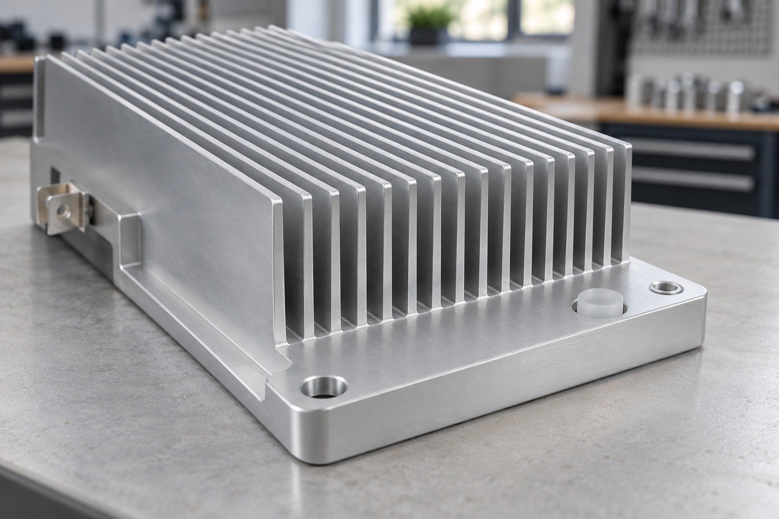
Accept the finished part against the mounting, appearance and specified functional requirements.
| Your final fit | Appearance and specified functional checks. |
|---|---|
| Your method | Datums, gauges and agreed measurement stage. |
| Your evidence | Sample revision, finish records and acceptance results. |
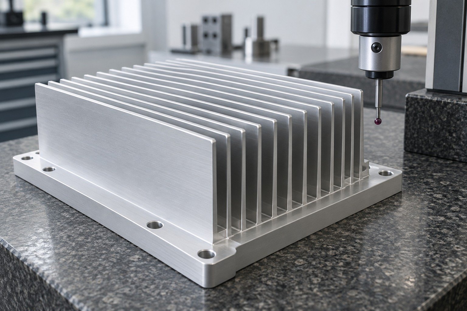
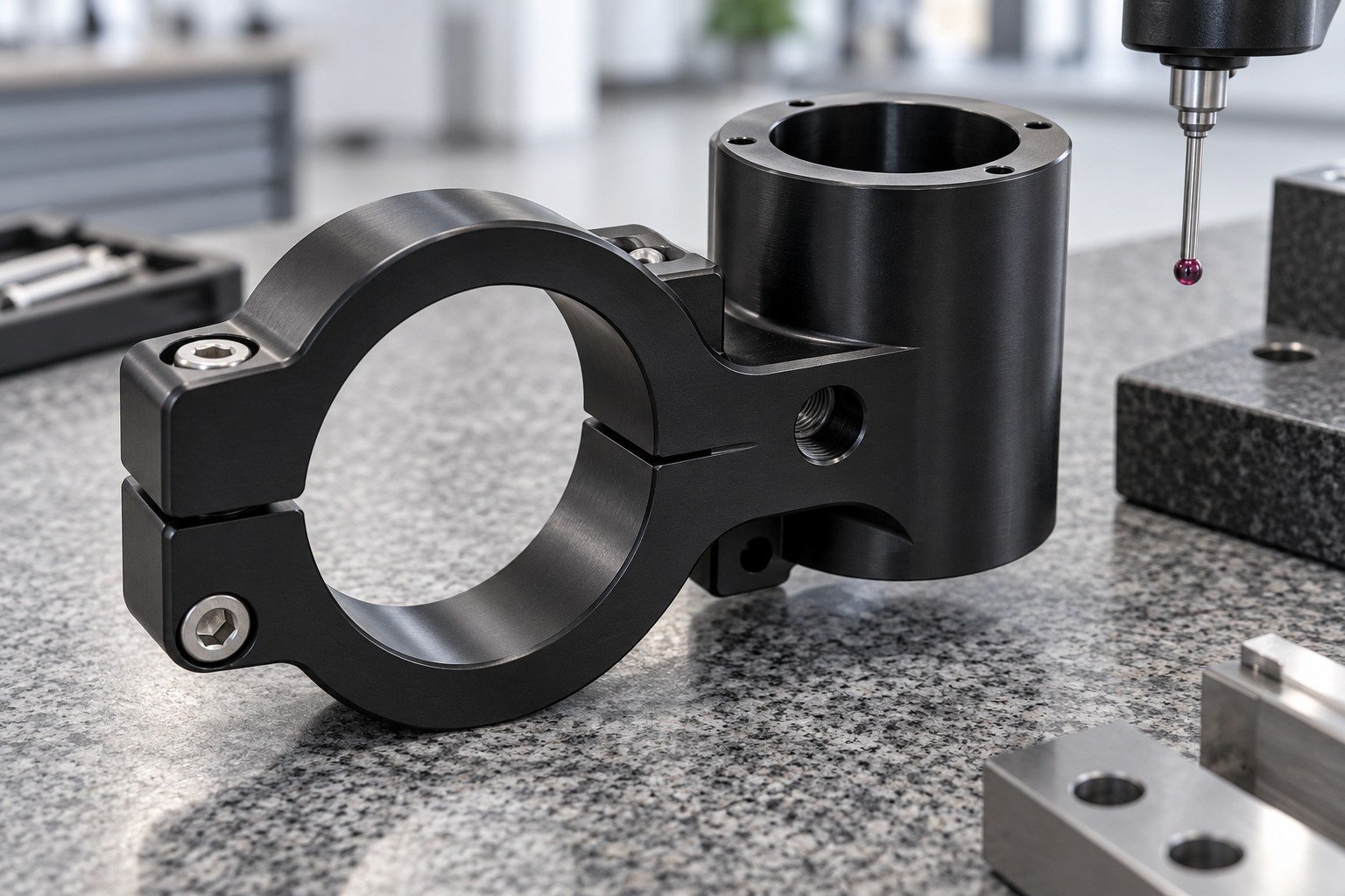
Review bore size, split clearance and mounting features in the final treated condition.
| Your interfaces | Clamp bore and locating faces. |
|---|---|
| Your appearance | Threads, split gaps and sensor interfaces. |
| Your approval | Mating gauge or actual assembly. |
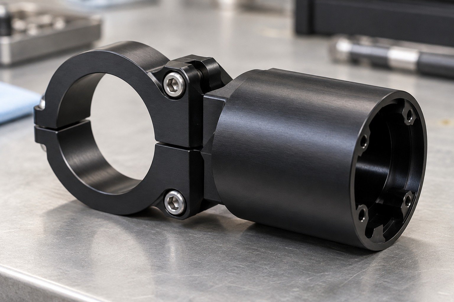
State the exact alloy and condition; choose the finish around wear, environment and mating features.
| Your substrate | Exact alloy, temper and incoming surface. |
|---|---|
| Your callout | Type, specification/revision, thickness and seal. |
| Your sample | Texture, color and agreed acceptance limits. |
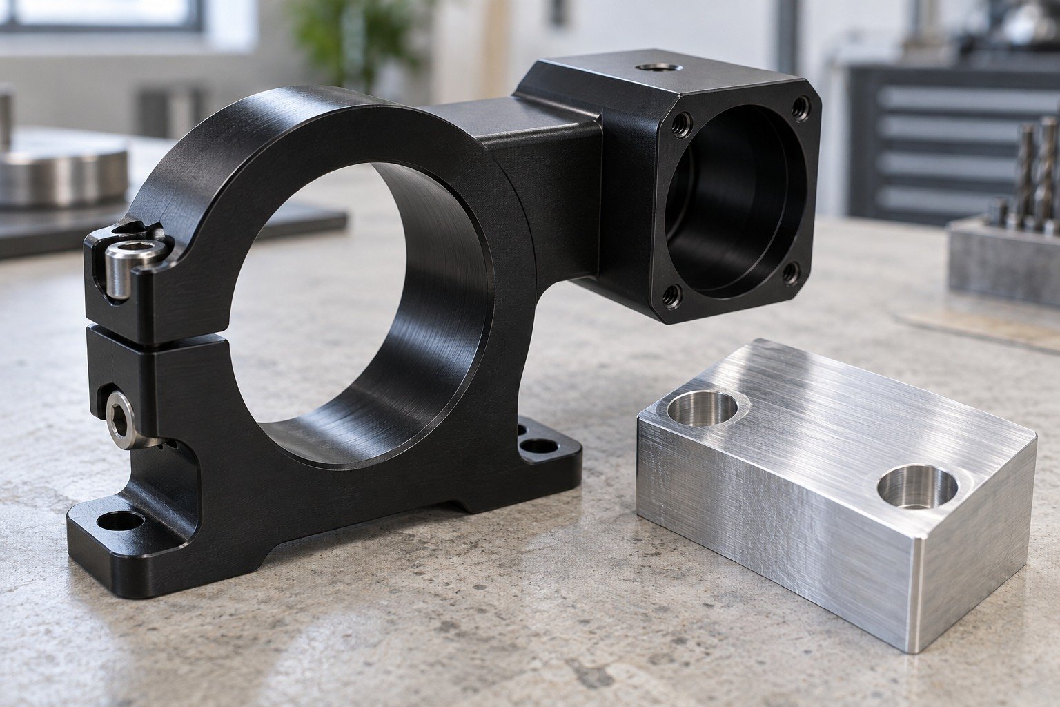
Identify tight bores and threads; agree plug boundaries and final inspection before processing.
| Your drawing | Clamp bore and locating faces. |
|---|---|
| Your boundaries | Threads, split gaps and sensor interfaces. |
| Your agreement | Rack contacts, mask transitions and final inspection. |
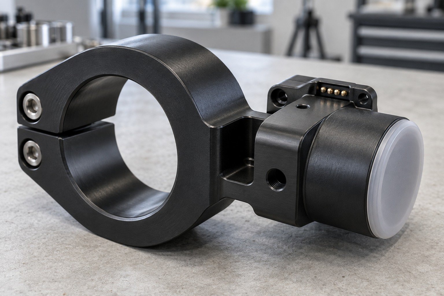
Use the approved gauge or mating part to assess the finished bore and assembly.
| Your final fit | Mating gauge or actual assembly. |
|---|---|
| Your method | Datums, gauges and agreed measurement stage. |
| Your evidence | Sample revision, finish records and acceptance results. |
Approve your texture and color sample before committing a complete panel set.
| Your interfaces | Customer-visible faces and controls. |
|---|---|
| Your appearance | Grain, color sample and mask boundaries. |
| Your approval | Lighting and viewing conditions. |
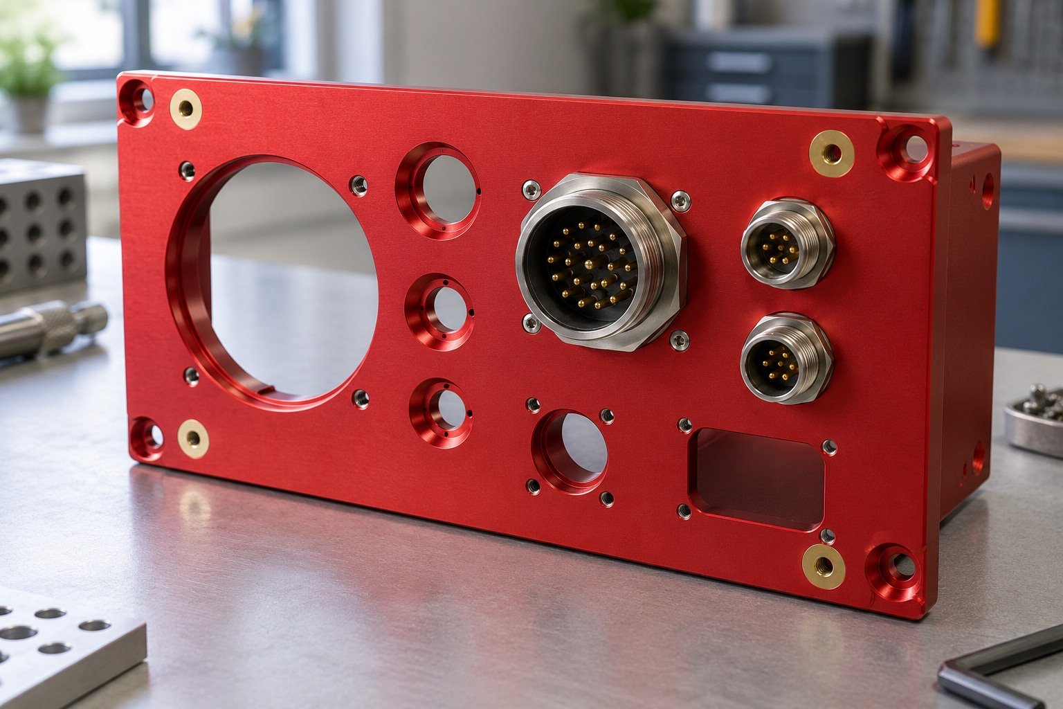
Specify the alloy, directional texture and agreed appearance sample; a color name alone is incomplete.
| Your substrate | Exact alloy, temper and incoming surface. |
|---|---|
| Your callout | Type, specification/revision, thickness and seal. |
| Your sample | Texture, color and agreed acceptance limits. |
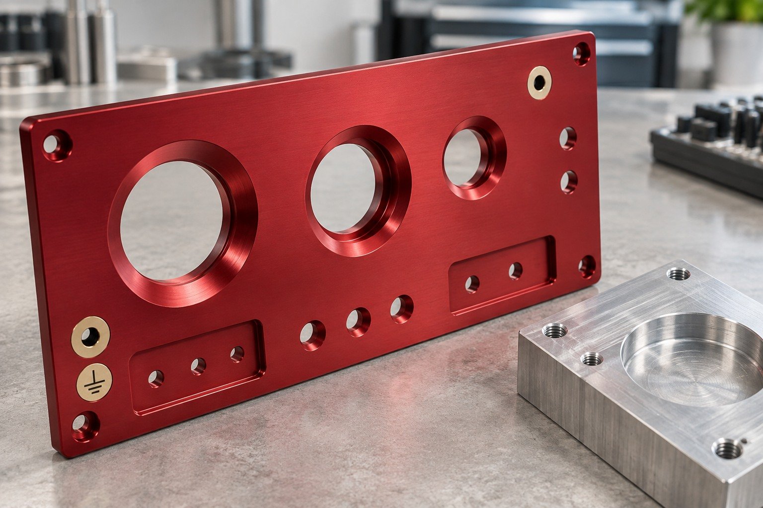
Locate rack contacts away from visible faces and define acceptable transition boundaries.
| Your drawing | Customer-visible faces and controls. |
|---|---|
| Your boundaries | Grain, color sample and mask boundaries. |
| Your agreement | Rack contacts, mask transitions and final inspection. |
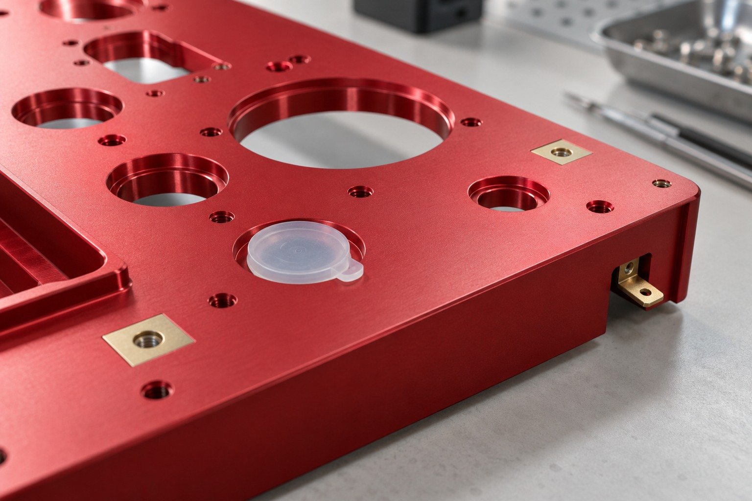
Compare the approved sample under agreed lighting, direction and viewing distance.
| Your final fit | Lighting and viewing conditions. |
|---|---|
| Your method | Datums, gauges and agreed measurement stage. |
| Your evidence | Sample revision, finish records and acceptance results. |
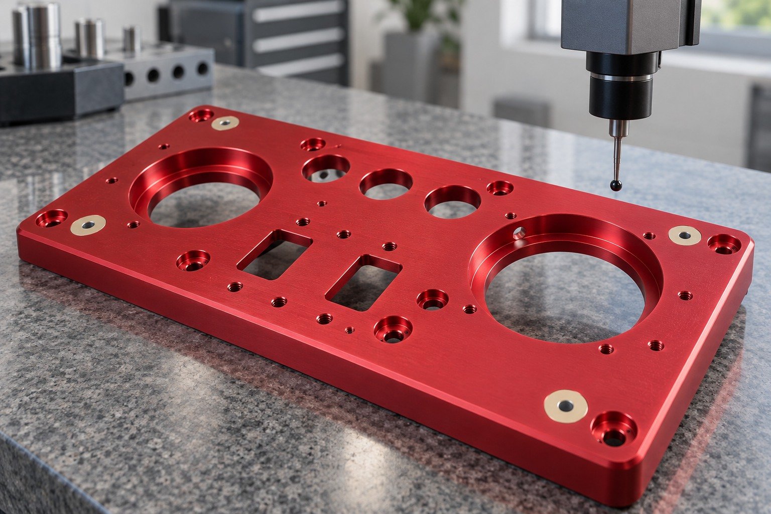
Identify the faces and holes that locate your assembly; avoid treating every surface as equally critical.
| Your interfaces | Locating bores and mounting surfaces. |
|---|---|
| Your appearance | Specified load interfaces and contact points. |
| Your approval | Final dimensions at approved datums. |
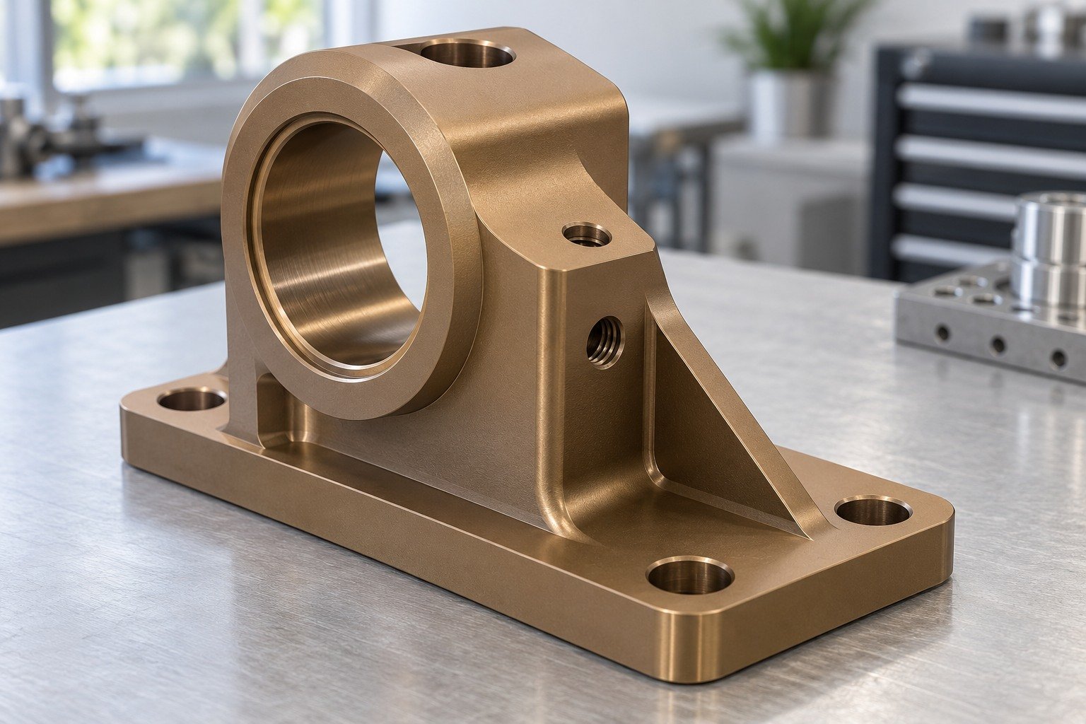
Review grade, delivery condition and existing welds before selecting the finish route.
| Your substrate | Exact alloy, temper and incoming surface. |
|---|---|
| Your callout | Type, specification/revision, thickness and seal. |
| Your sample | Texture, color and agreed acceptance limits. |
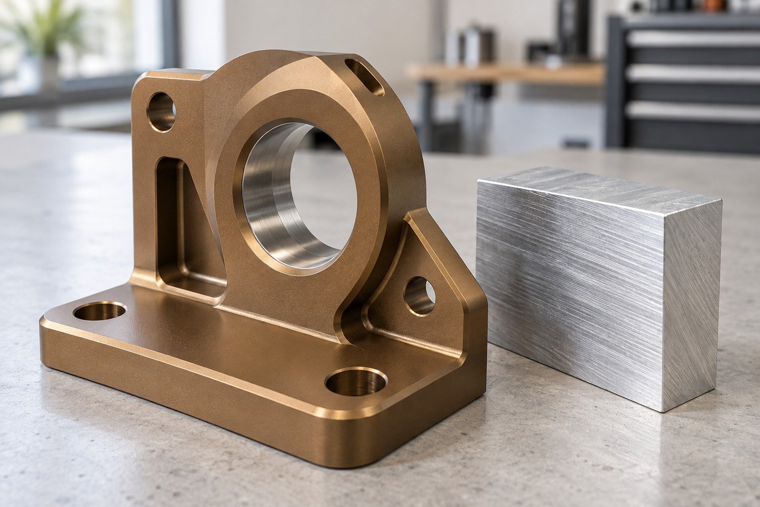
Mark mounting faces, bores and any conductive interfaces on the drawing.
| Your drawing | Locating bores and mounting surfaces. |
|---|---|
| Your boundaries | Specified load interfaces and contact points. |
| Your agreement | Rack contacts, mask transitions and final inspection. |
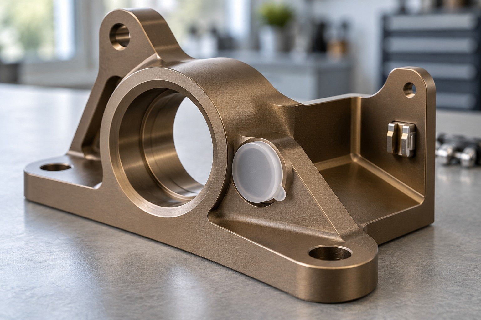
Measure the final mounting interfaces and record the approved drawing revision.
| Your final fit | Final dimensions at approved datums. |
|---|---|
| Your method | Datums, gauges and agreed measurement stage. |
| Your evidence | Sample revision, finish records and acceptance results. |
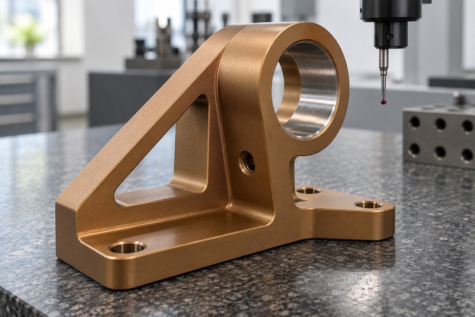
For a wear-focused finish, specify the service conditions, mating material and agreed acceptance tests.
| Your interfaces | Sliding faces and fixture datums. |
|---|---|
| Your appearance | Wear requirement and finish specification. |
| Your approval | Finished gauge and functional fit. |
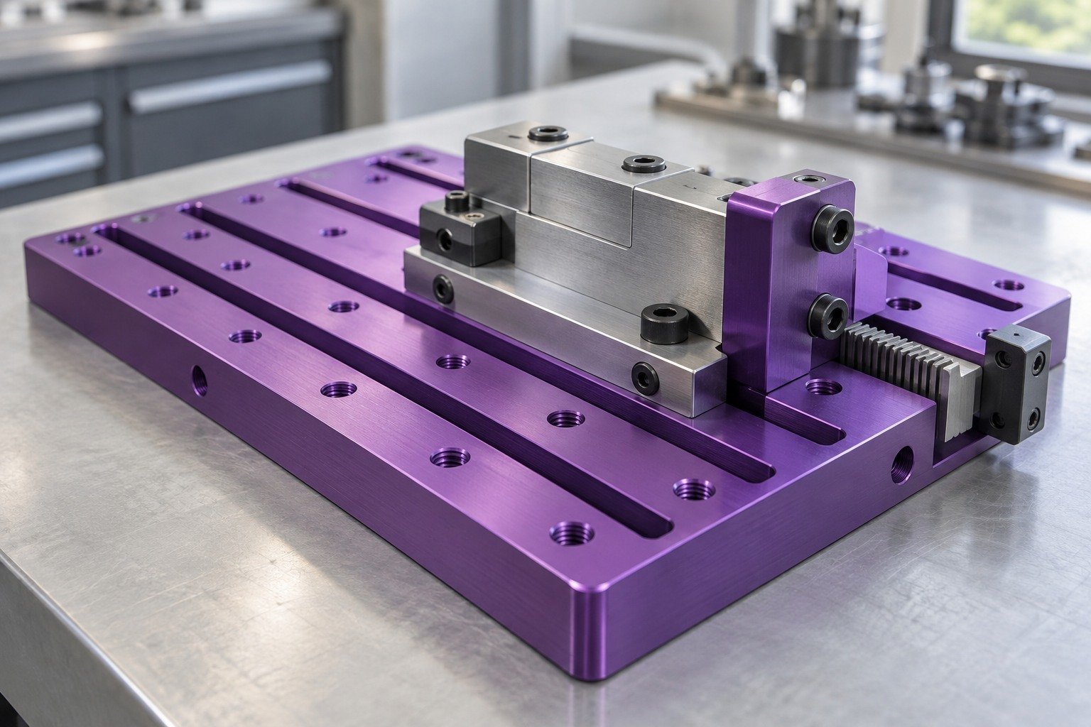
Compare Type II and Type III requirements around wear, fit and sealing; supplier feasibility must be confirmed.
| Your substrate | Exact alloy, temper and incoming surface. |
|---|---|
| Your callout | Type, specification/revision, thickness and seal. |
| Your sample | Texture, color and agreed acceptance limits. |
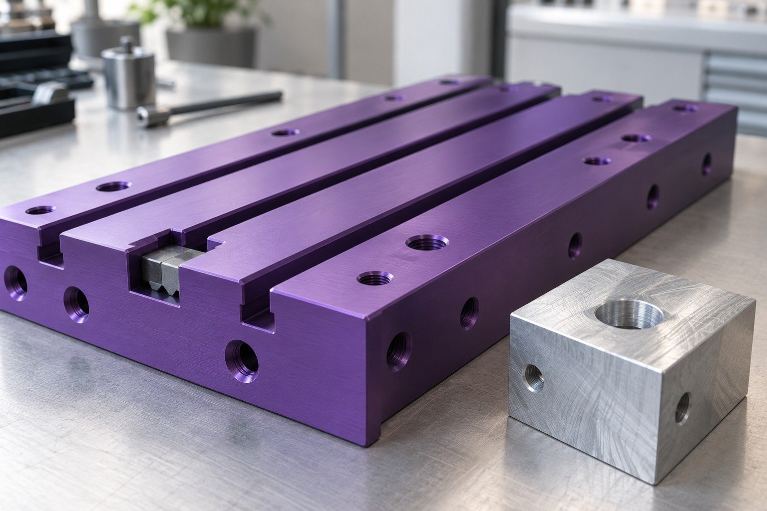
Agree how sliding surfaces, threaded holes and locating datums are protected or finished.
| Your drawing | Sliding faces and fixture datums. |
|---|---|
| Your boundaries | Wear requirement and finish specification. |
| Your agreement | Rack contacts, mask transitions and final inspection. |
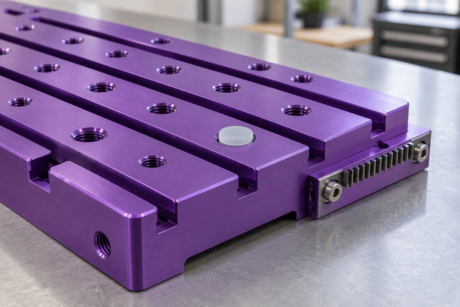
Verify the specified finished dimensions and any agreed wear-related evidence; appearance alone is insufficient.
| Your final fit | Finished gauge and functional fit. |
|---|---|
| Your method | Datums, gauges and agreed measurement stage. |
| Your evidence | Sample revision, finish records and acceptance results. |
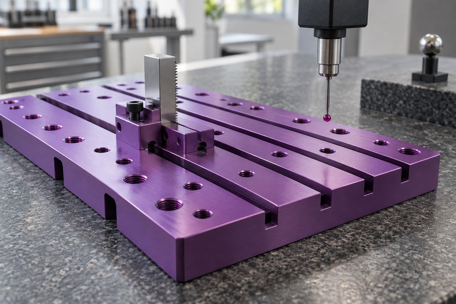
Bring the intended part function, exact material and controlled finish callout into one review.
| Your interfaces | Controlled drawing and alloy condition. |
|---|---|
| Your appearance | Your critical finish and masking requirements. |
| Your approval | Agreed sample and inspection records. |
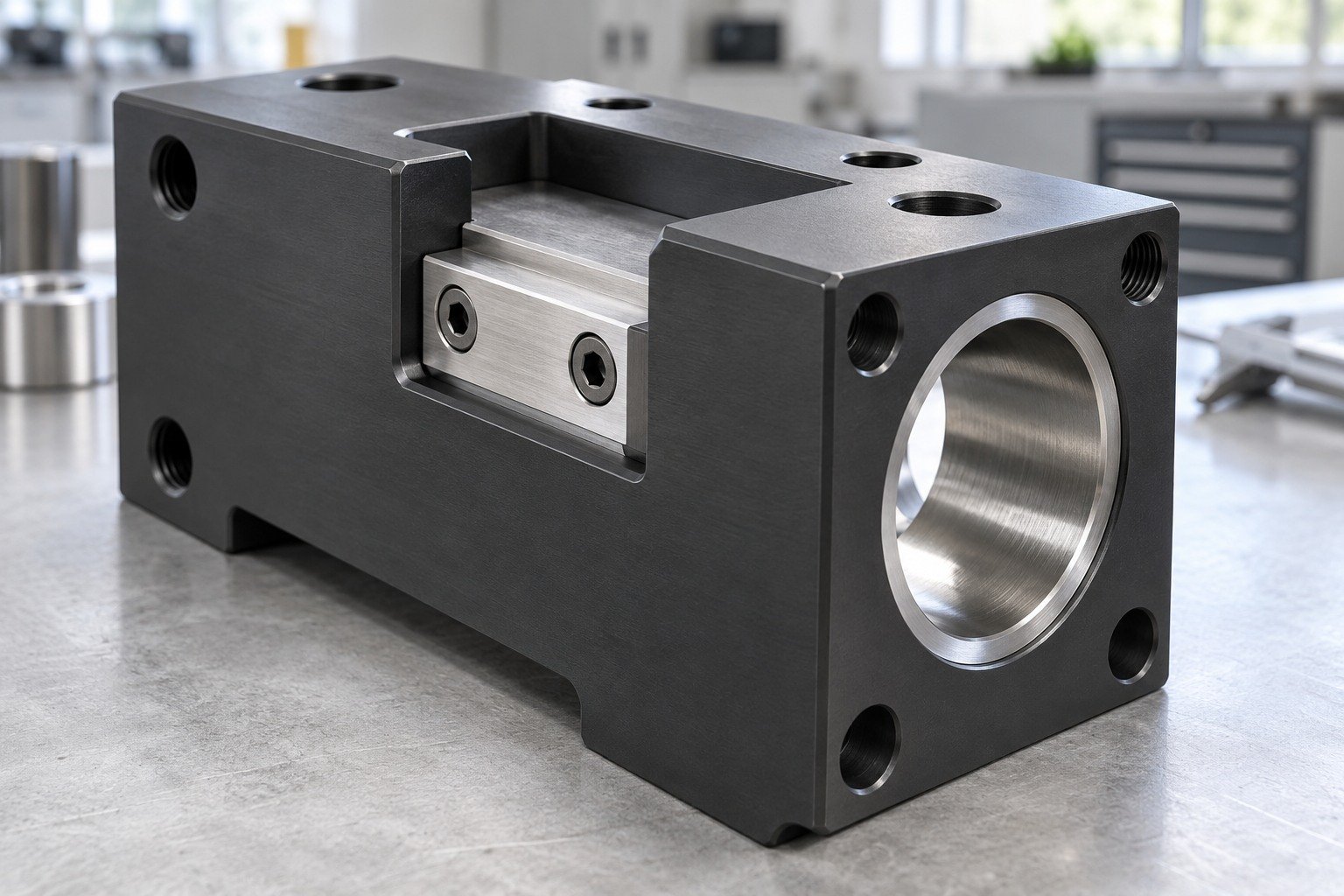
Use the complete drawing specification and service environment rather than a general request for a durable finish.
| Your substrate | Exact alloy, temper and incoming surface. |
|---|---|
| Your callout | Type, specification/revision, thickness and seal. |
| Your sample | Texture, color and agreed acceptance limits. |
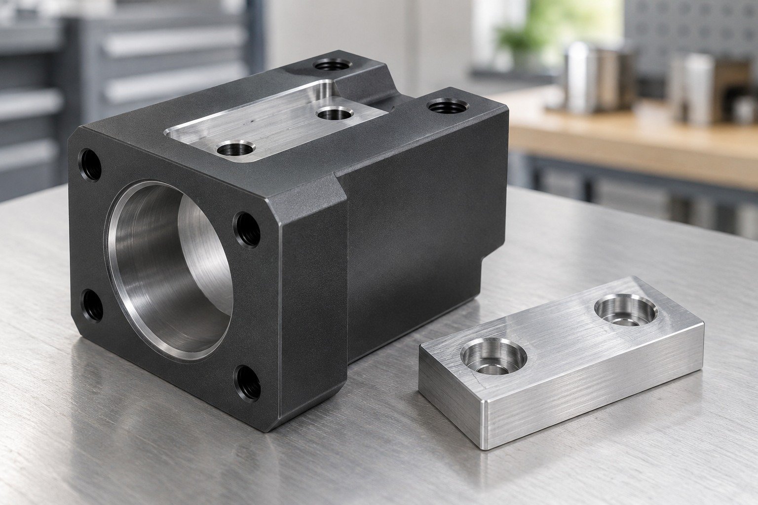
Review masking access, rack contact positions and inspection access with the actual geometry.
| Your drawing | Controlled drawing and alloy condition. |
|---|---|
| Your boundaries | Your critical finish and masking requirements. |
| Your agreement | Rack contacts, mask transitions and final inspection. |
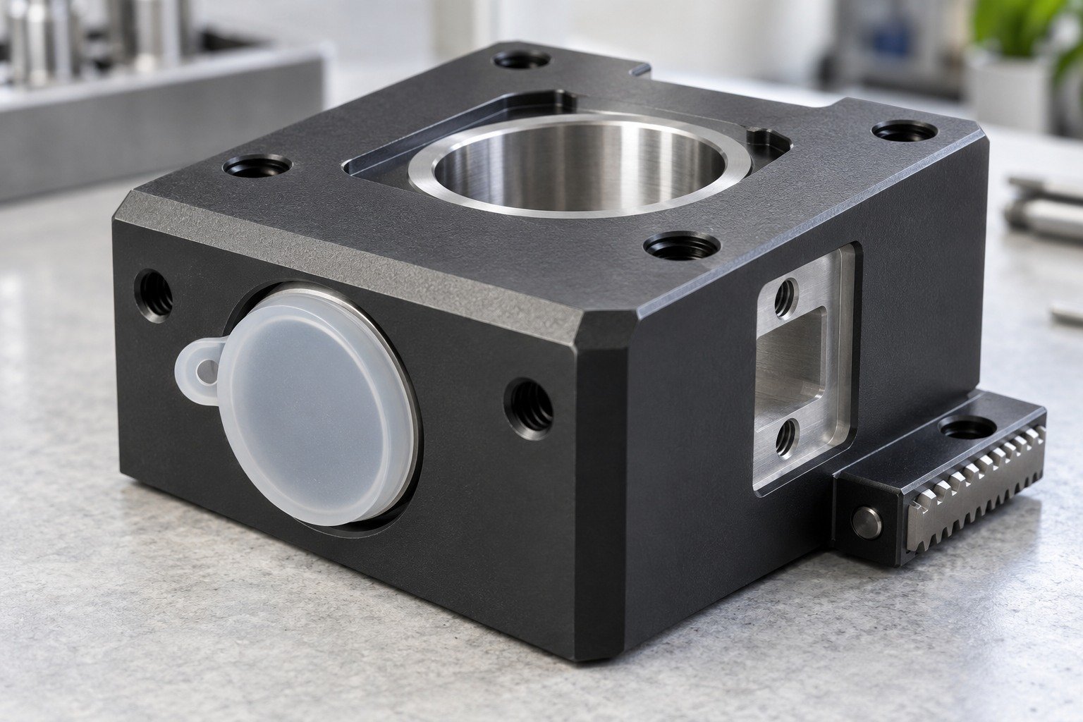
Agree sample quantity, measurement state and records before repeat orders.
| Your final fit | Agreed sample and inspection records. |
|---|---|
| Your method | Datums, gauges and agreed measurement stage. |
| Your evidence | Sample revision, finish records and acceptance results. |
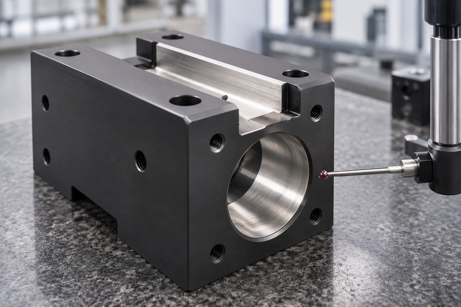
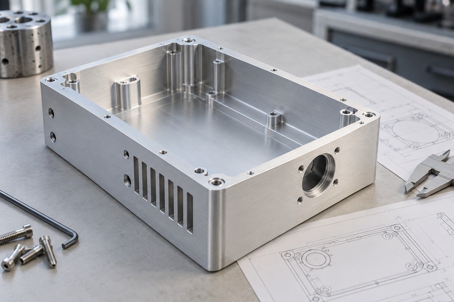
Share alloy, condition, quantity, service environment and delivery requirements.
An untreated or painted look-alike does not establish the performance or appearance of your specified anodized finish.
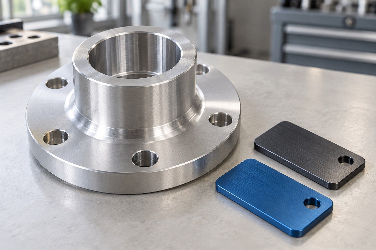
Review Type II or hardcoat anodizing as specified; confirm supplier scope, seal requirements and inspection evidence.
An untreated or painted look-alike does not establish the performance or appearance of your specified anodized finish.
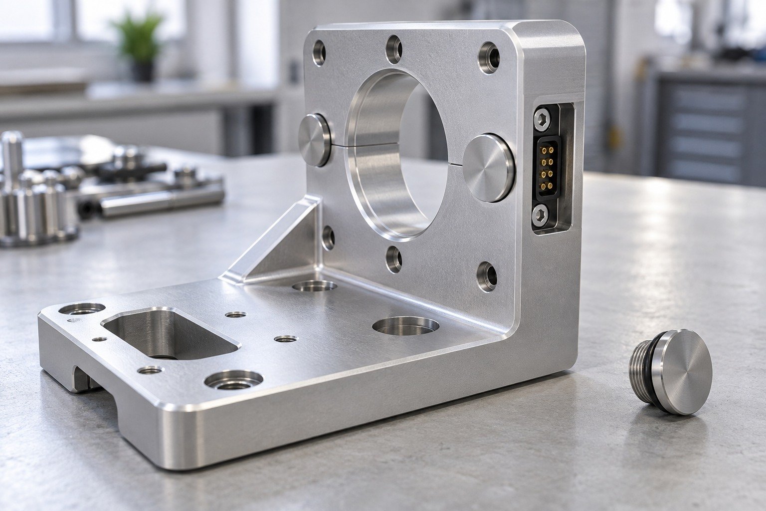
Mark critical bores, threads, electrical contacts, visible faces and allowed rack contact marks.
An untreated or painted look-alike does not establish the performance or appearance of your specified anodized finish.
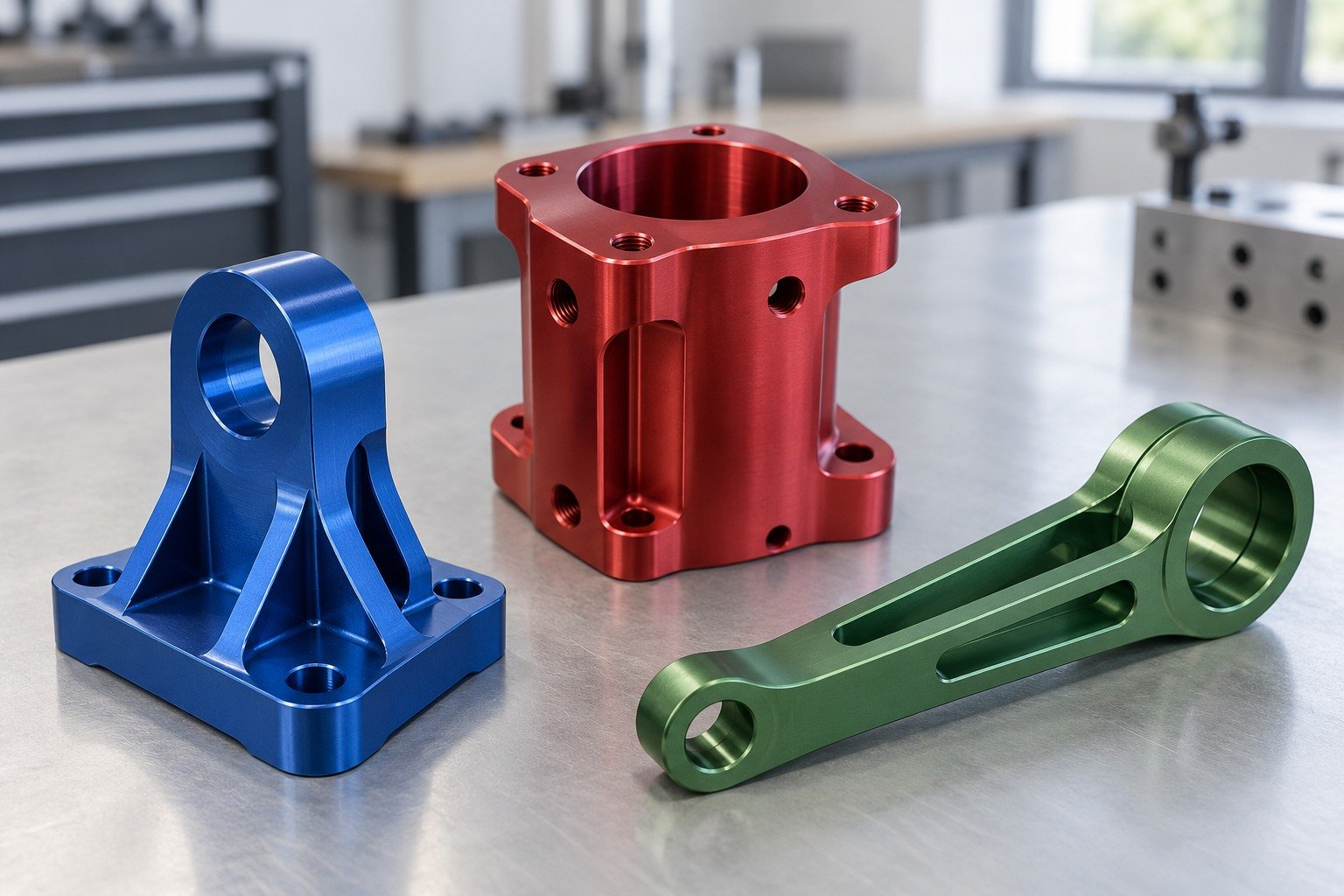
Check final dimensions, color, texture and mask boundaries on representative treated parts.
An untreated or painted look-alike does not establish the performance or appearance of your specified anodized finish.
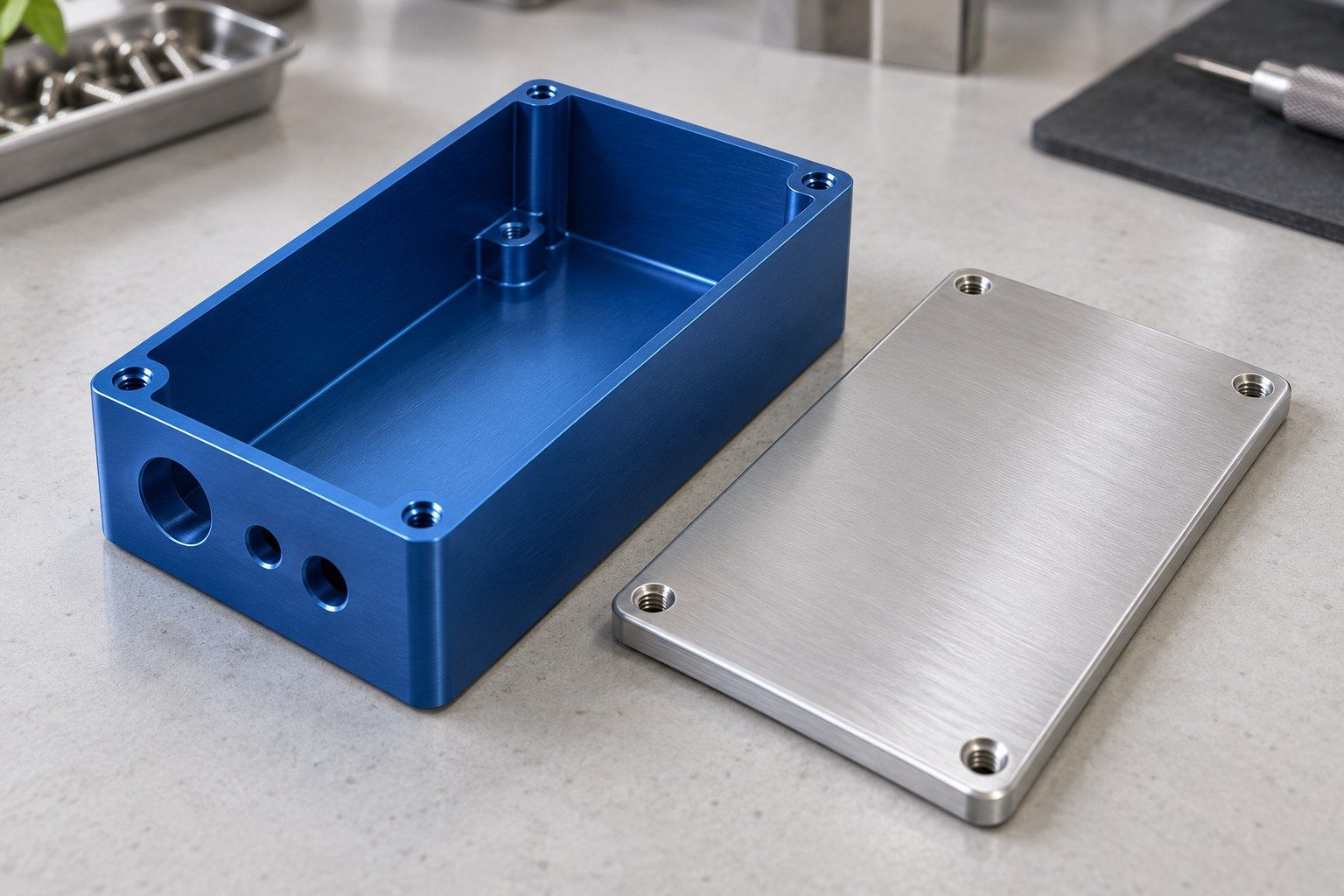
Record agreed changes, sample results, finish callout and release authority before production.
An untreated or painted look-alike does not establish the performance or appearance of your specified anodized finish.
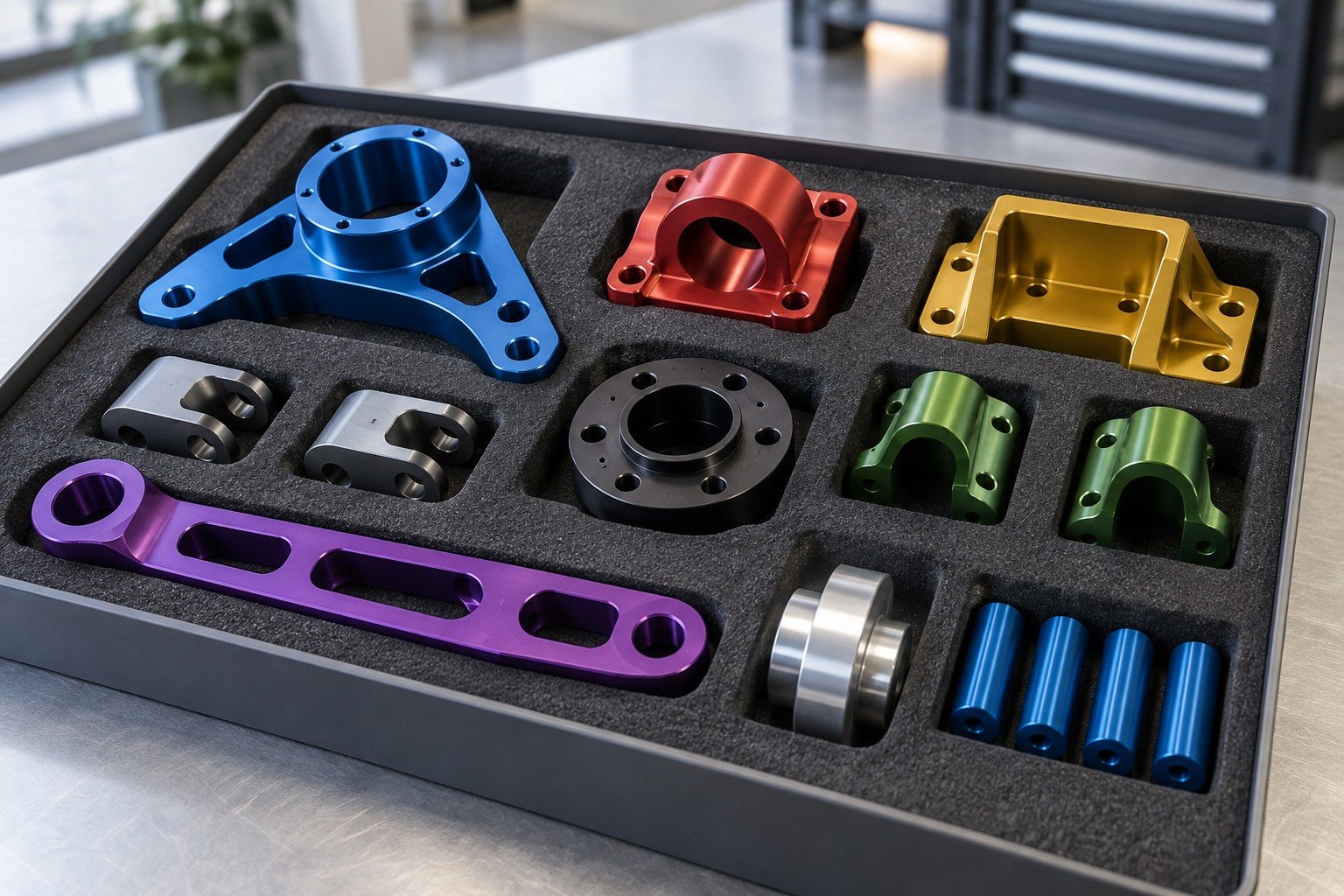
Identify the approved revision, sample reference, packaging and records on subsequent orders.
An untreated or painted look-alike does not establish the performance or appearance of your specified anodized finish.
Use these anodizing design guidelines to define the interfaces your assembly depends on.
Anodizing thickness and outward growth are different quantities. Review dimensional allowance for the specific finish and geometry; do not assume one growth ratio for every job.
| Your drawing | Before-treatment and final dimensions with datums. |
|---|---|
| Our review | Specified thickness, outward growth and measurement plan. |
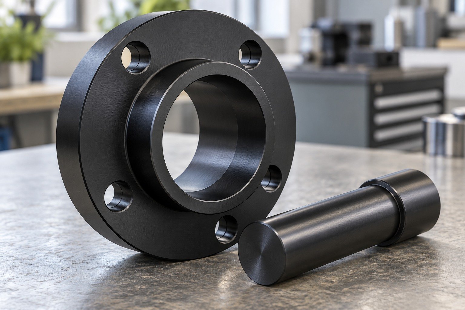
State thread and bore acceptance in the finished condition. Anodizing masking, allowance or an approved secondary operation may be needed.
| Your input | Thread callout, gauge and critical bore limits. |
|---|---|
| Our review | Masking feasibility and final fit checks. |
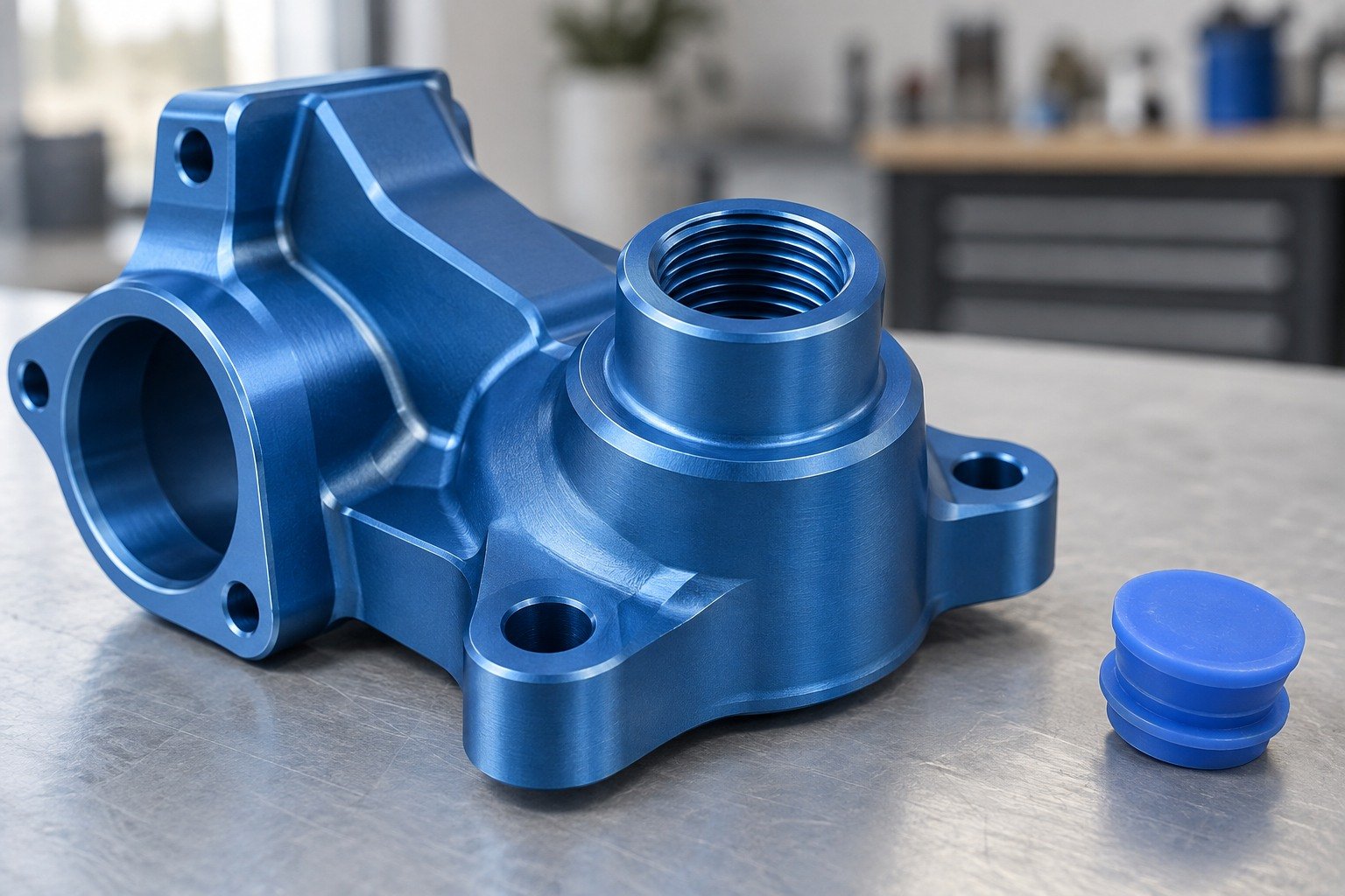
Identify grounding, bonding and other conductive interfaces explicitly. Define mask boundaries and final contact requirements.
| Your input | Contact areas and clear boundary dimensions. |
|---|---|
| Our review | Masking method, transitions and inspection access. |
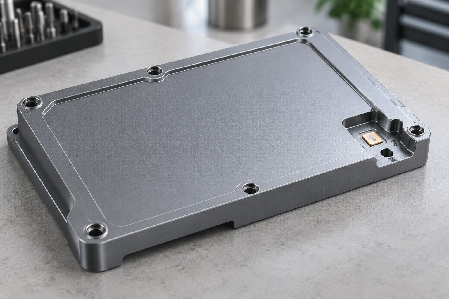
Electrical contact is needed during processing. Agree the location and acceptable appearance of rack marks outside your critical cosmetic zones.
| Your input | Visible zones and acceptable hidden surfaces. |
|---|---|
| Our review | Rack contact location and sample appearance. |
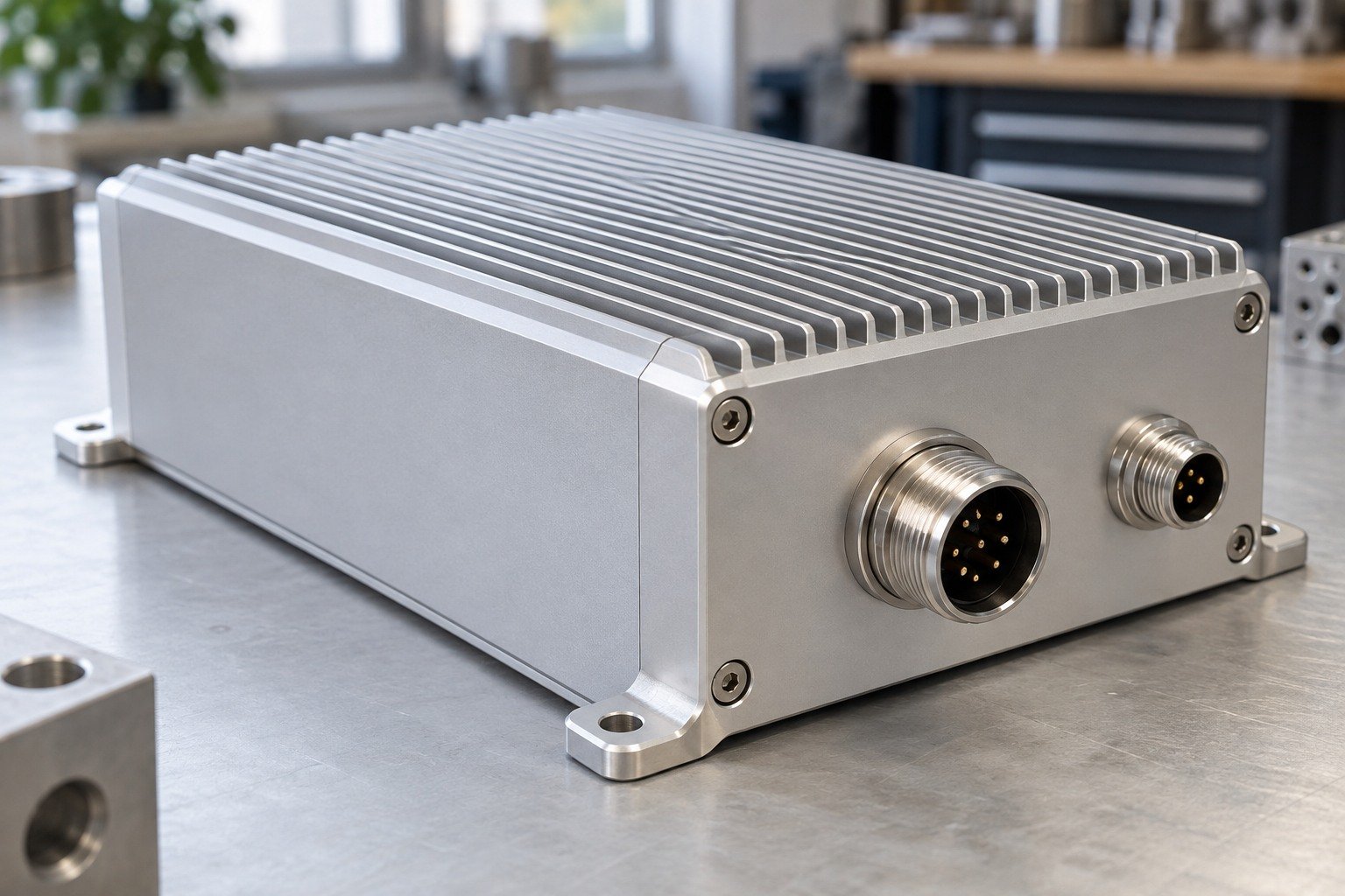
Alloy, surface condition, pretreatment and the chosen process affect anodizing colors. Compare physical samples under agreed viewing conditions.
| Your input | Alloy, texture, master sample and viewing conditions. |
|---|---|
| Our review | Representative treated sample and variation limits. |
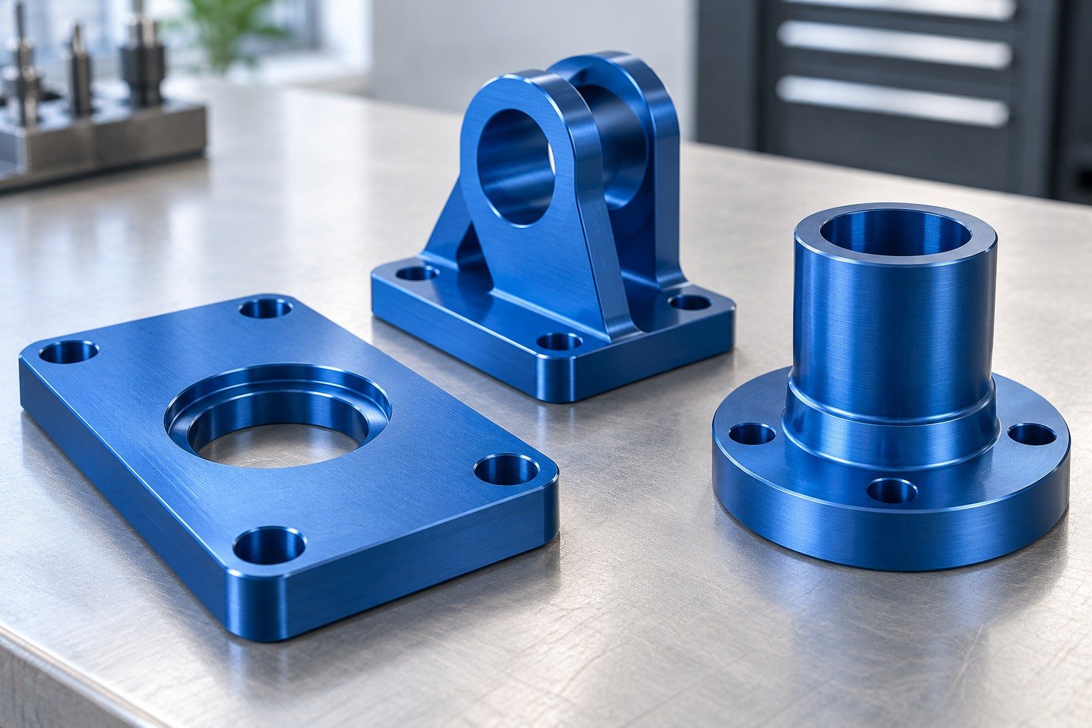
A shaft, slot or sliding interface must work after the finish is complete. Review both mating components and their treatment states.
| Your input | Counterpart, clearance and service environment. |
|---|---|
| Our review | Finished mating state and usable gauges. |
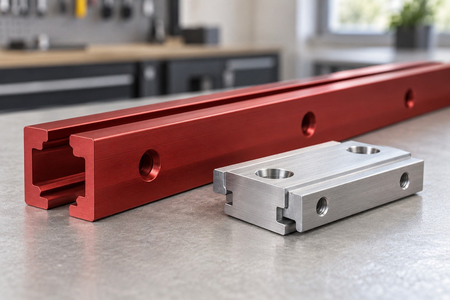
Review blind features, pockets, sharp edges and drainage with the processor; masking and rinsing access are geometry-specific.
| Your input | Full geometry and internal features. |
|---|---|
| Our review | Access, drainage and feature-specific finish scope. |
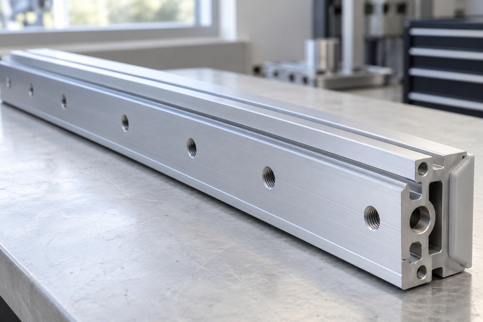
Anodizing surface finish starts with the substrate. Define machining marks, brushing direction or blast texture before approving a sample.
| Your input | Original surface and desired texture. |
|---|---|
| Our review | Pretreatment, appearance sample and handling. |
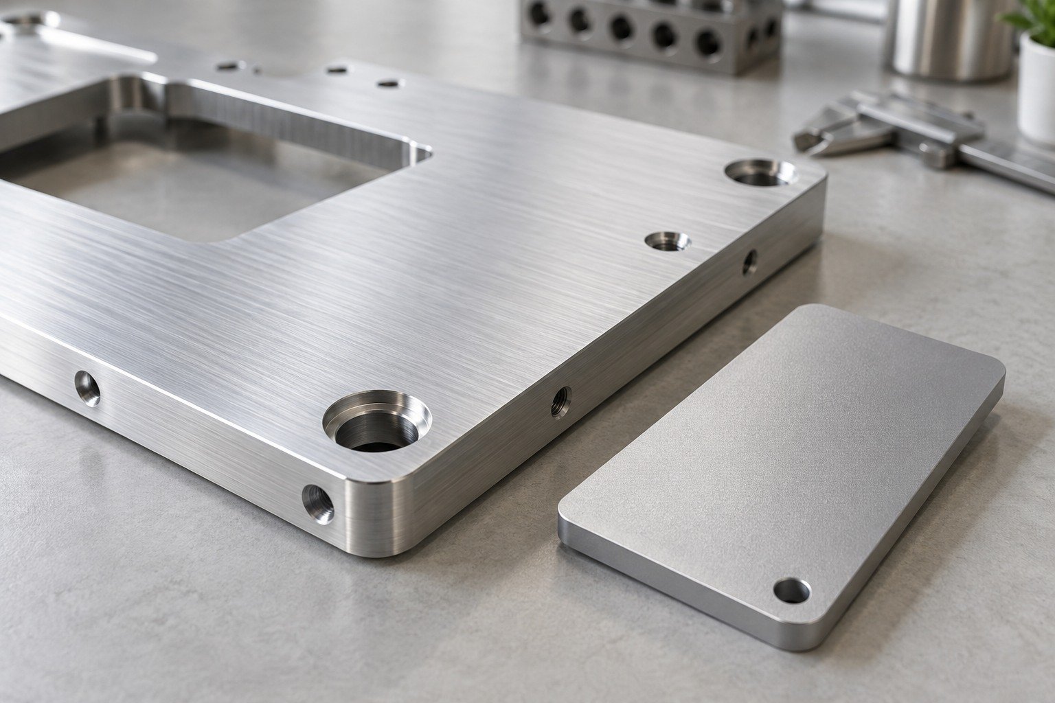
Material names and color names alone do not define an acceptable finished part.
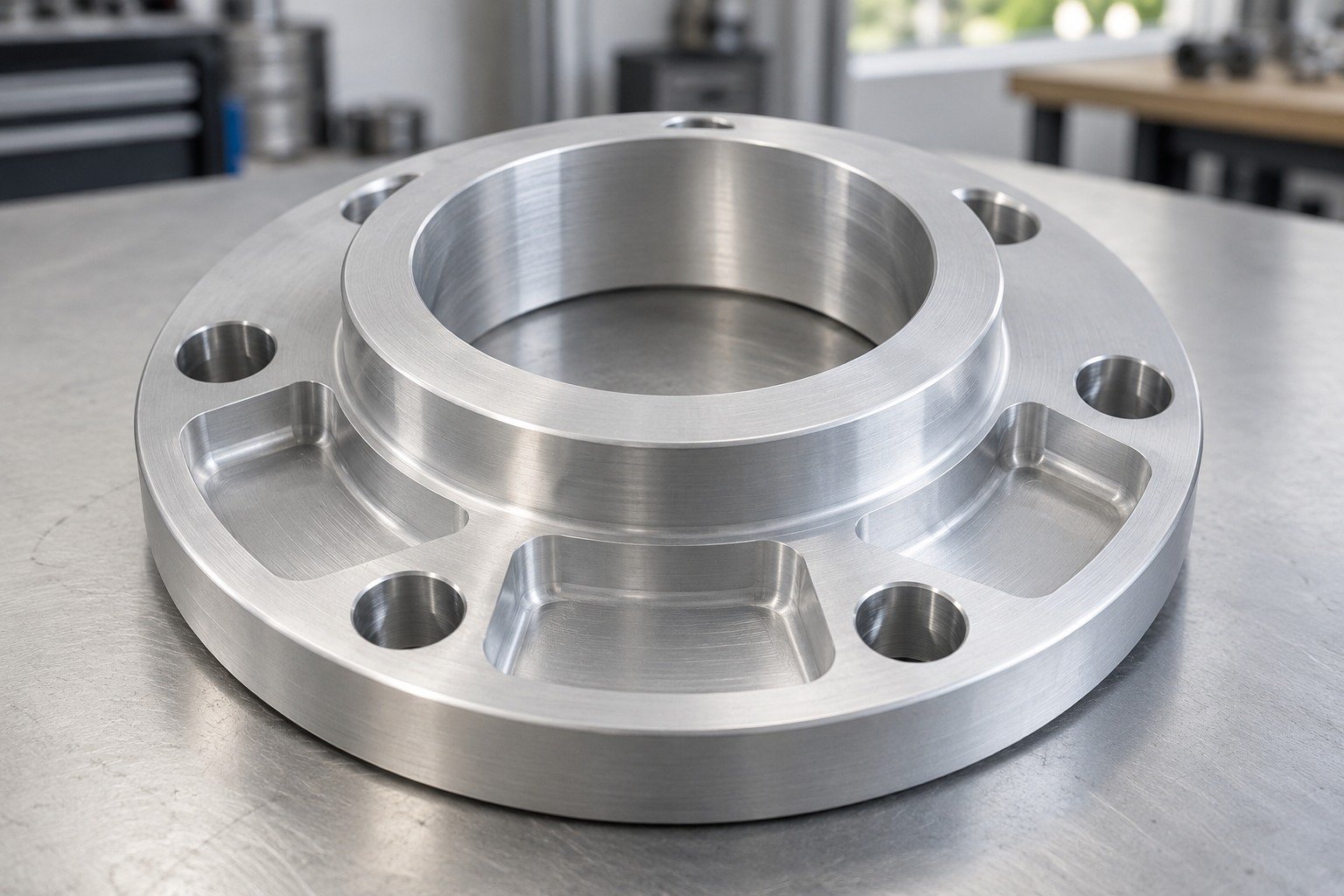
For anodizing 6061 aluminum, identify temper, machining state, cosmetic faces and final dimensions.
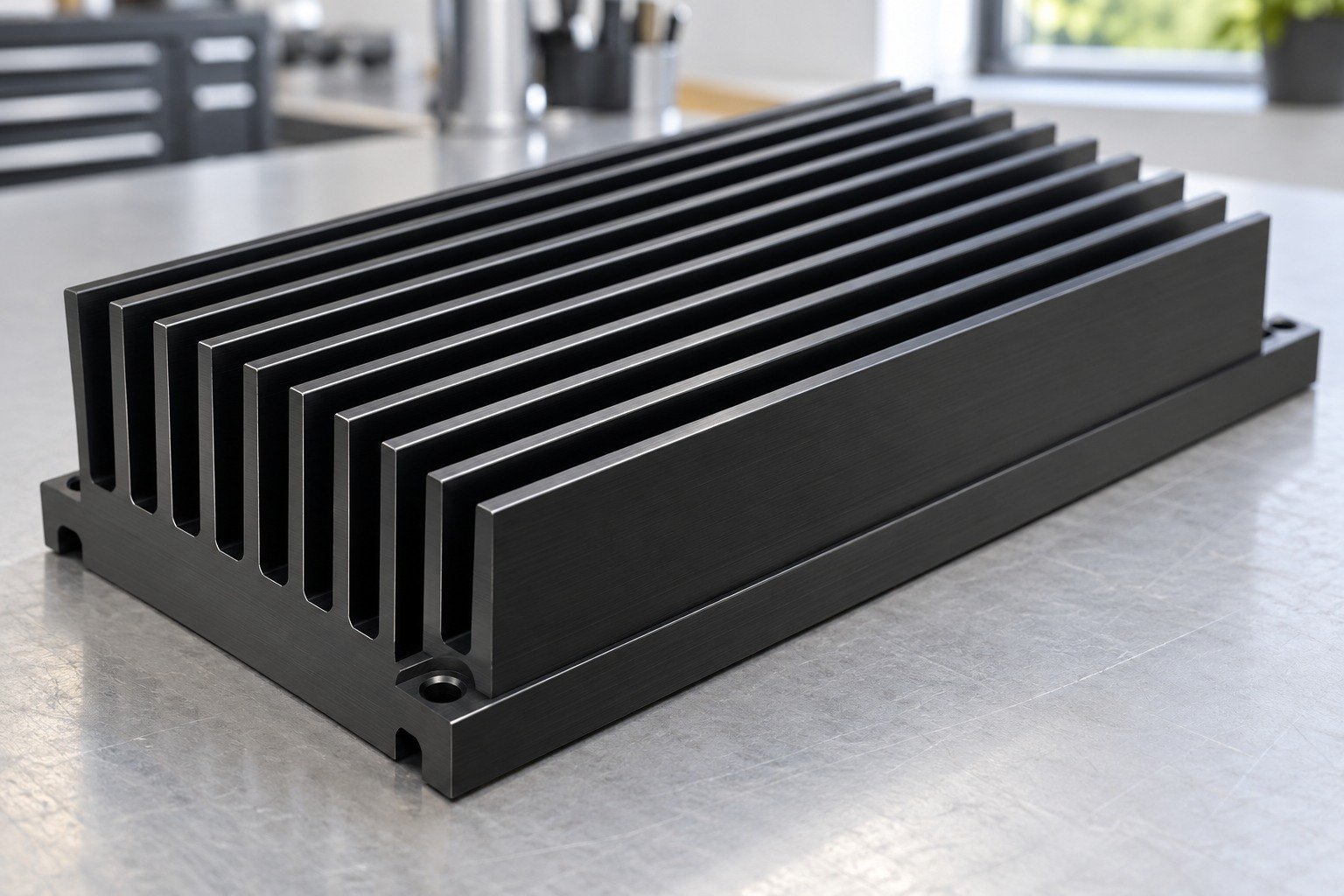
For anodizing 6063 aluminum, review extrusion surface, handling marks and the intended appearance.
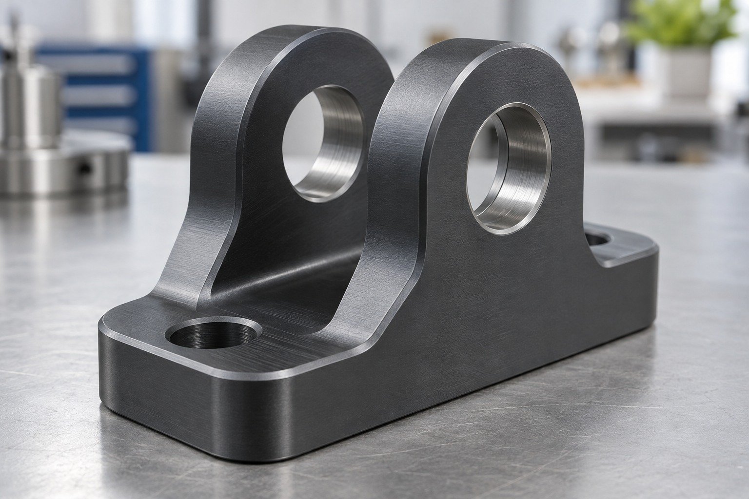
For anodizing 7075 aluminum, confirm grade, condition and the complete finish specification.
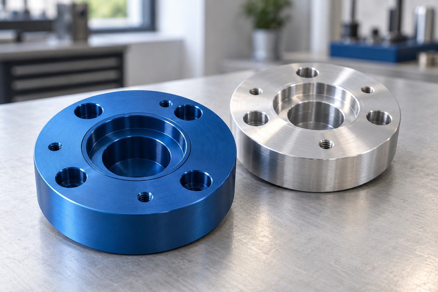
Clear anodizing is undyed anodic oxide, not clear paint. Black anodizing and other colors require agreed samples.
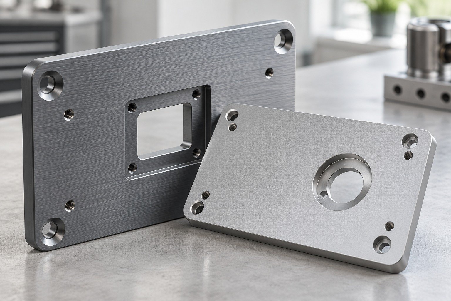
Brushed anodized aluminum needs an agreed grain direction. Bead blast anodizing requires a defined pretreatment texture.
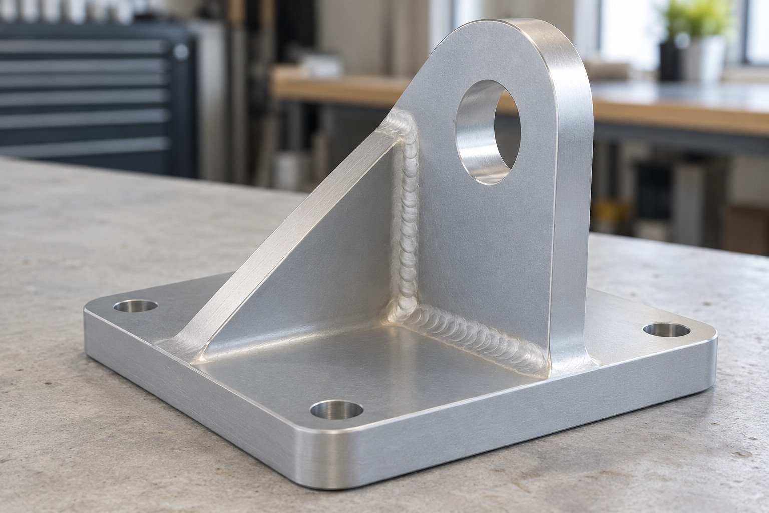
Review filler metal, weld zones and casting alloy separately; appearance may differ from wrought stock.
Type II anodizing is commonly used for protective and decorative finishes; Type III anodizing is a hardcoat route for specified wear-focused requirements. Thickness, sealing and supplier capability require project review. No certification or universal performance is implied.
Compare the same delivered condition rather than a color-only price.
Agree alloy, callout, masks and critical fit.
Review actual color, texture and final dimensions.
Control drawing, master sample and order scope.
PLANNING EXAMPLE — NOT A PRICE OR MINIMUM ORDER
Illustrates repeated masking scope only. Actual setup, labor and feasibility are reviewed for your geometry.
The anodizing process converts the aluminum surface to an anodic oxide layer; it is different from applying paint or depositing a metal plating.
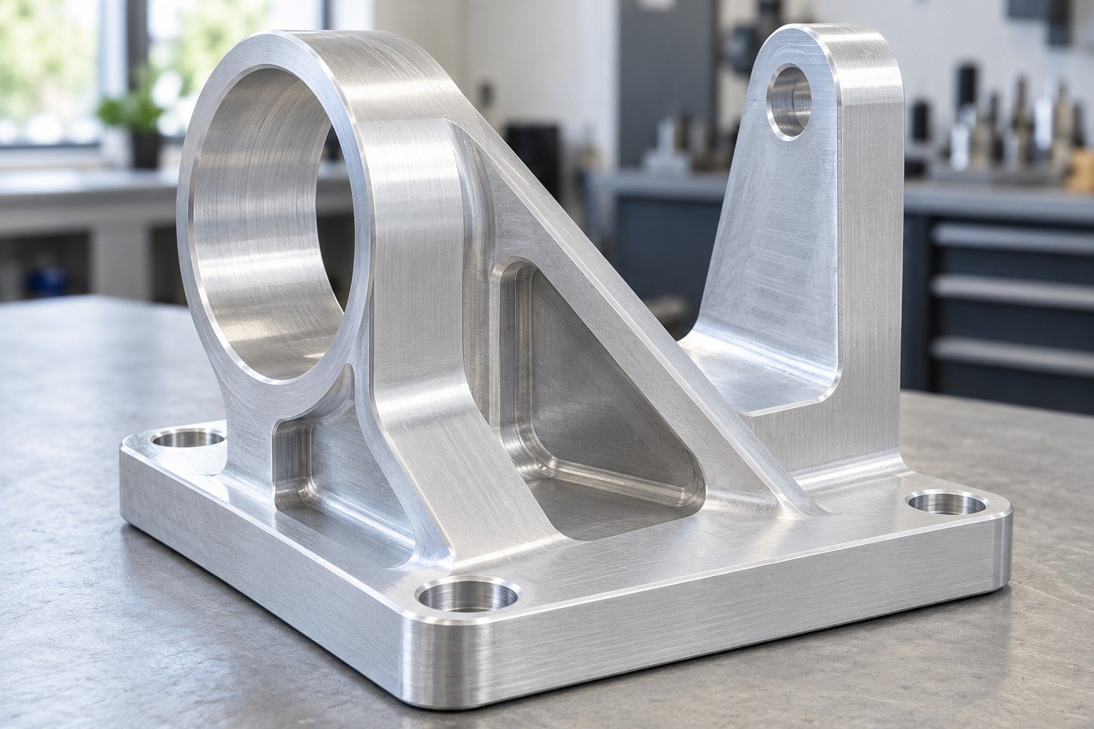
Confirm the incoming surface and finish callout.
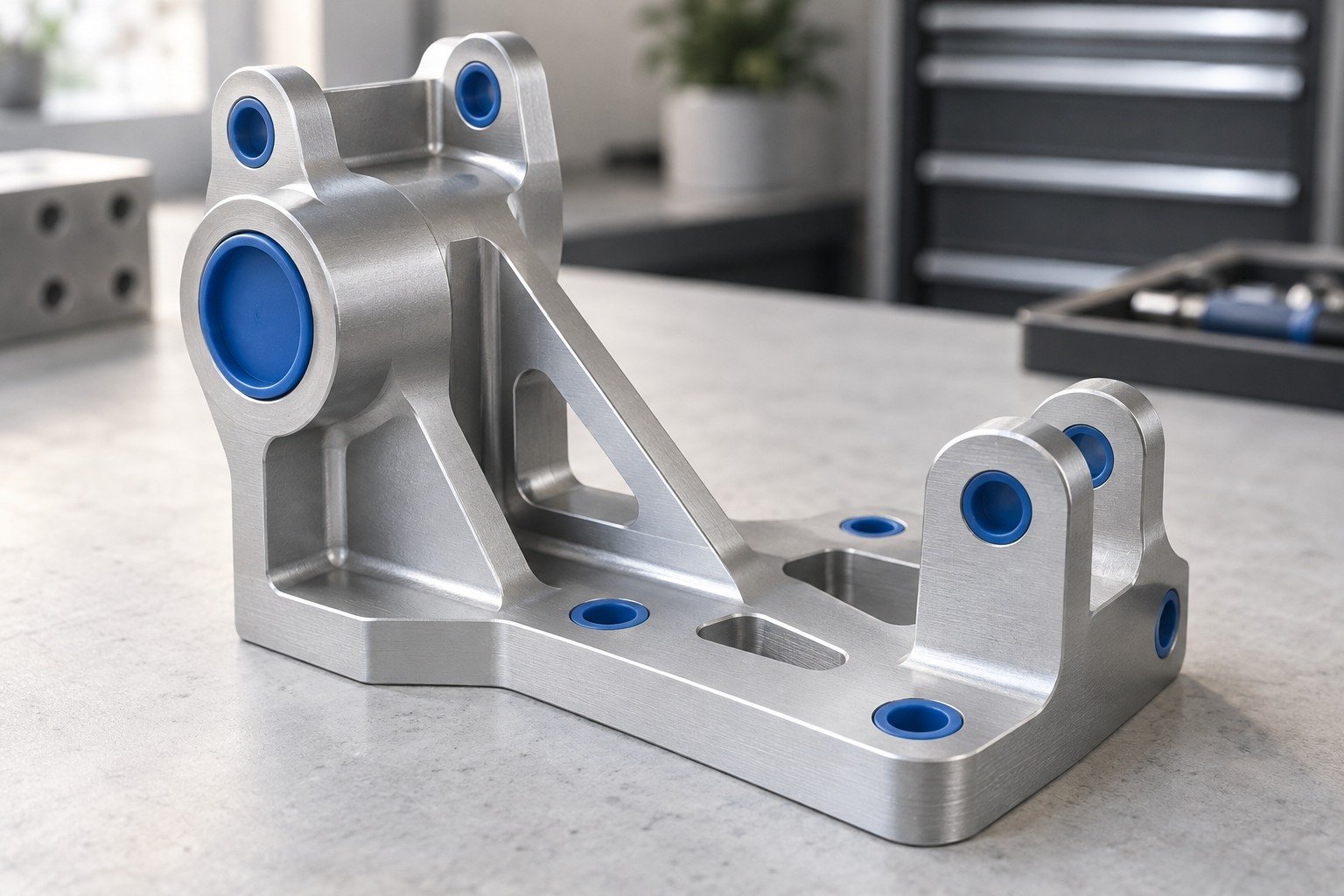
Protect agreed features and select contact positions.
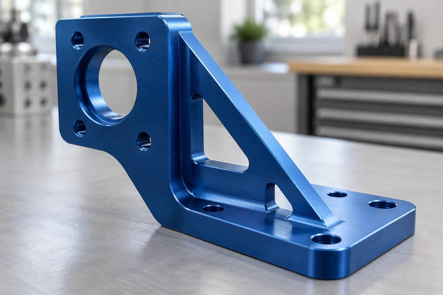
Apply the approved process, color and seal requirements.
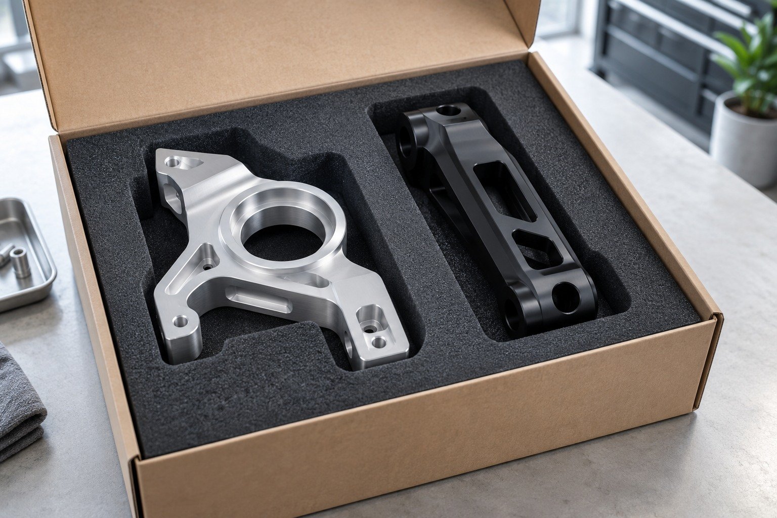
Check final fit and appearance; protect surfaces for delivery.
Pretreatment, dyeing, anodizing sealing and any secondary work follow the agreed specification. Confirm exact scope in your quotation.
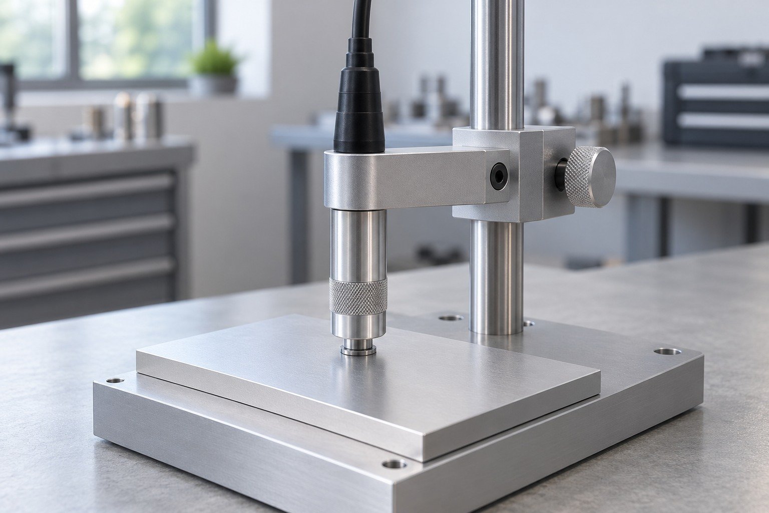
Define anodizing tolerances by feature and finished state; agree sampling and evidence before production.
| Alloy & Revision | Grade, condition and controlled drawing. |
|---|---|
| Type & Thickness | Specification, required locations and method. |
| Color & Texture | Approved sample and viewing conditions. |
| Masks & Contacts | Boundary positions and allowed rack marks. |
| Final Dimensions | Bores, threads, mating faces and gauges. |
| Release Evidence | Agreed inspection records and part protection. |
Agree required thickness, seal or other specified tests and records. A dimensional report alone does not establish corrosion resistance, wear performance or compliance.
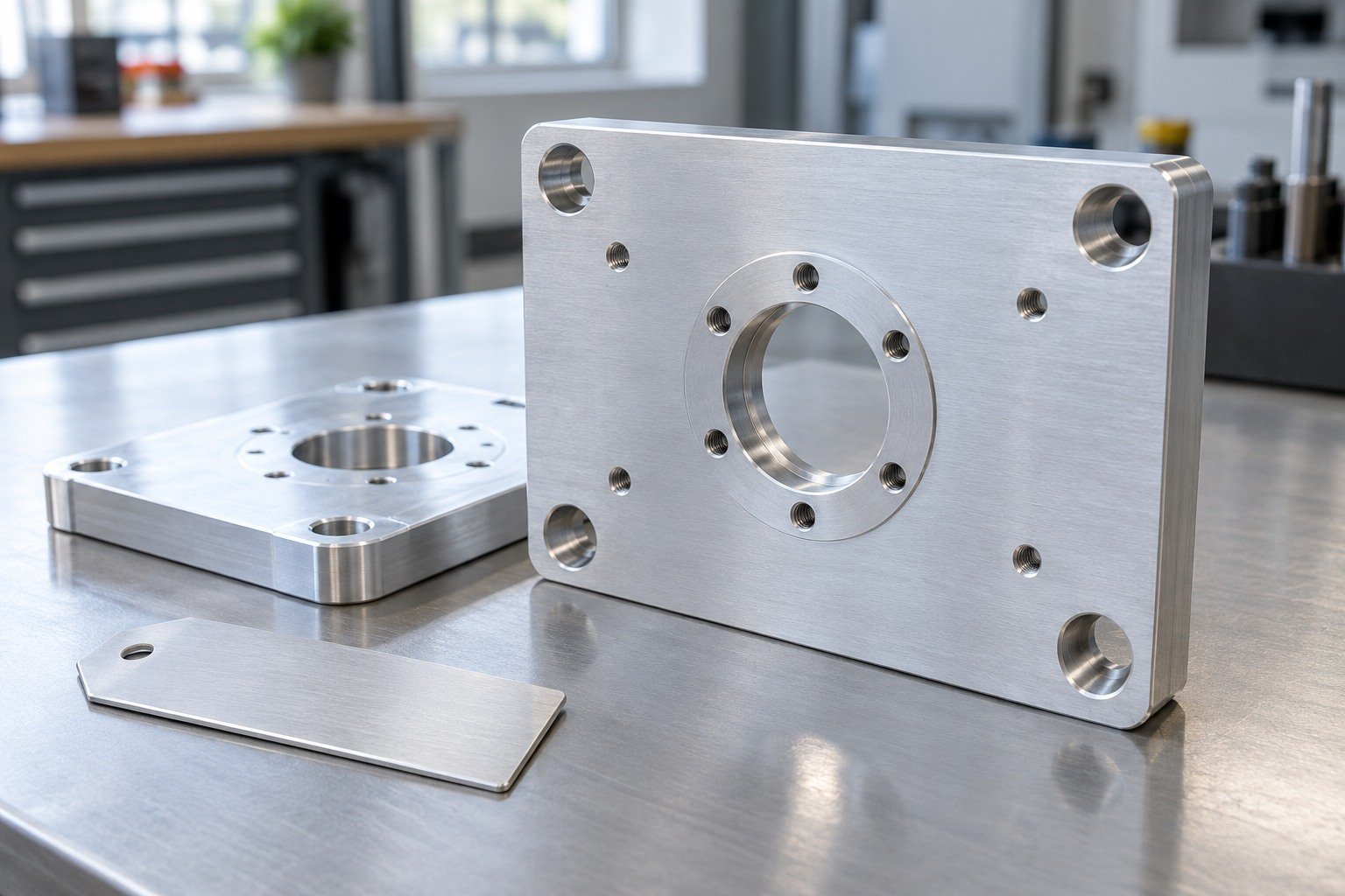
| Alloy & Revision | Grade, condition and controlled drawing. |
|---|---|
| Type & Thickness | Specification, required locations and method. |
| Color & Texture | Approved sample and viewing conditions. |
| Masks & Contacts | Boundary positions and allowed rack marks. |
| Final Dimensions | Bores, threads, mating faces and gauges. |
| Release Evidence | Agreed inspection records and part protection. |
Agree required thickness, seal or other specified tests and records. A dimensional report alone does not establish corrosion resistance, wear performance or compliance.
| Alloy & Revision | Grade, condition and controlled drawing. |
|---|---|
| Type & Thickness | Specification, required locations and method. |
| Color & Texture | Approved sample and viewing conditions. |
| Masks & Contacts | Boundary positions and allowed rack marks. |
| Final Dimensions | Bores, threads, mating faces and gauges. |
| Release Evidence | Agreed inspection records and part protection. |
Agree required thickness, seal or other specified tests and records. A dimensional report alone does not establish corrosion resistance, wear performance or compliance.
| Alloy & Revision | Grade, condition and controlled drawing. |
|---|---|
| Type & Thickness | Specification, required locations and method. |
| Color & Texture | Approved sample and viewing conditions. |
| Masks & Contacts | Boundary positions and allowed rack marks. |
| Final Dimensions | Bores, threads, mating faces and gauges. |
| Release Evidence | Agreed inspection records and part protection. |
Agree required thickness, seal or other specified tests and records. A dimensional report alone does not establish corrosion resistance, wear performance or compliance.
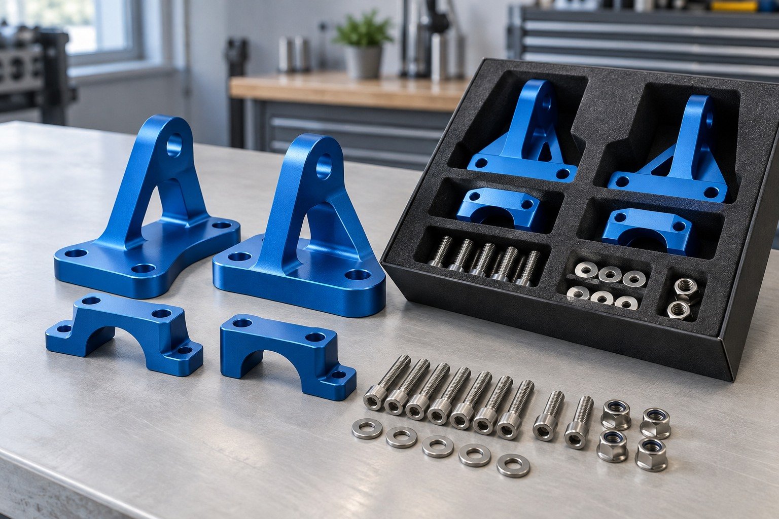
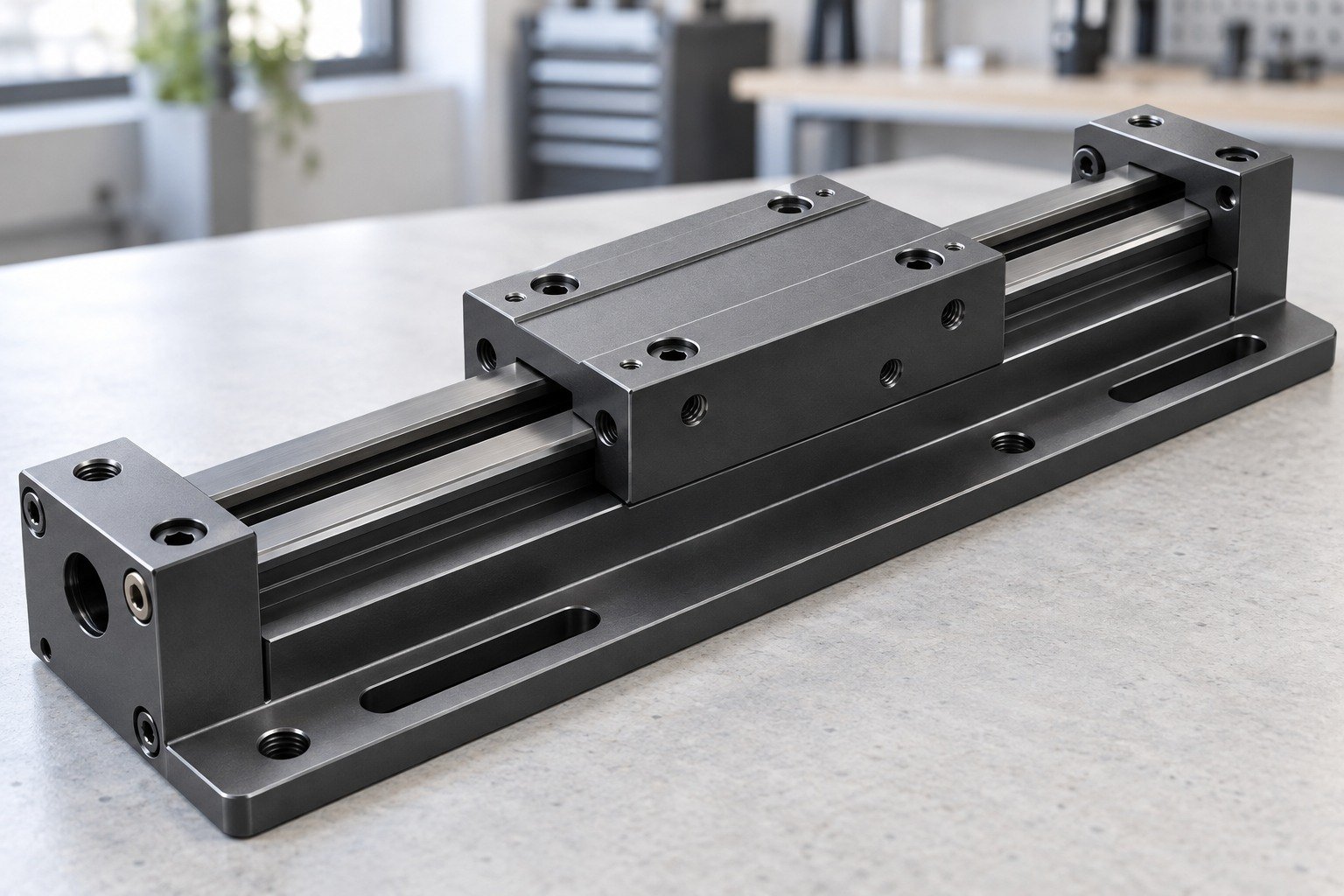
Anodizing for industrial equipment starts with wear, mounting and maintenance needs.
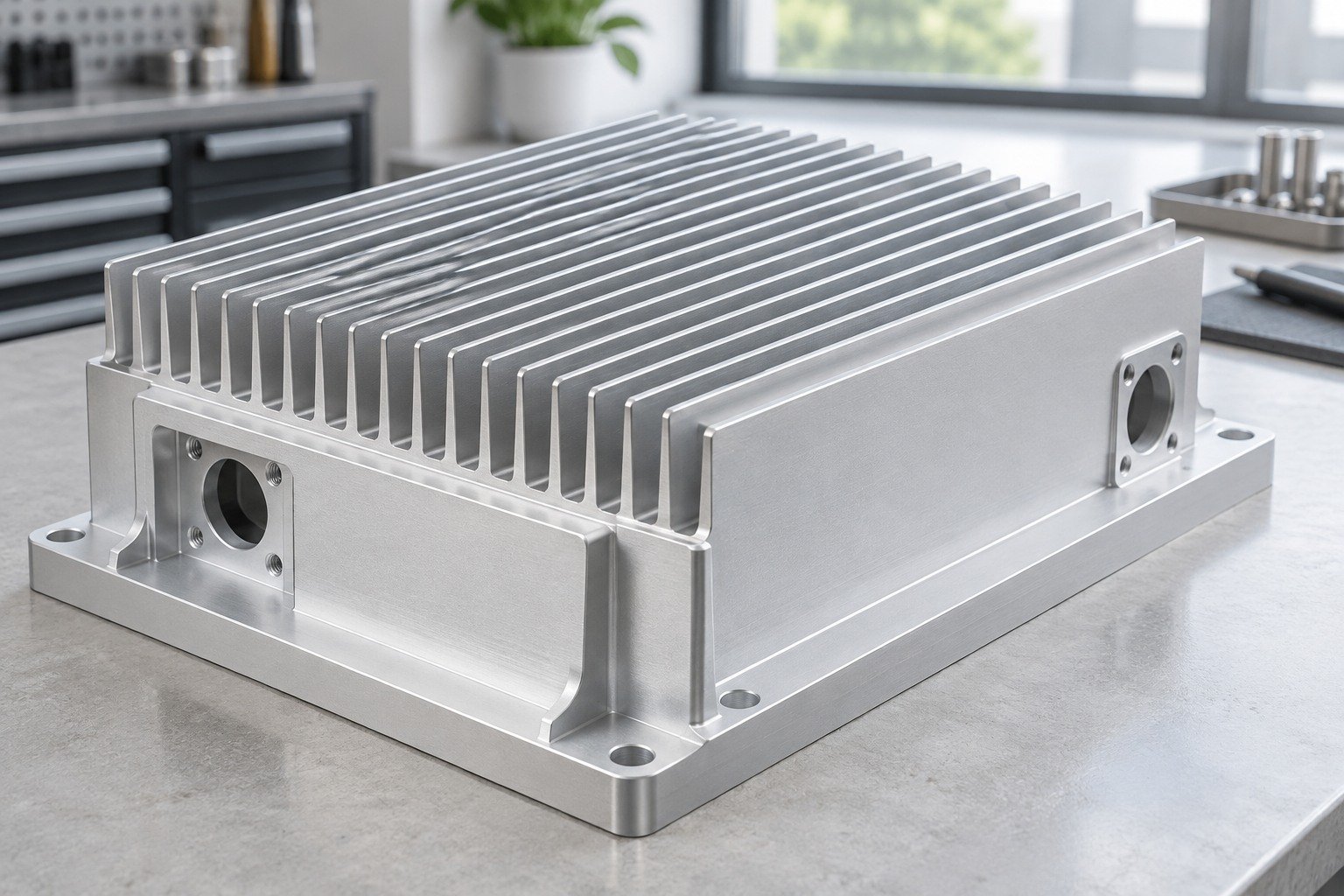
Specify thermal-contact faces, mounting geometry and finish requirements.
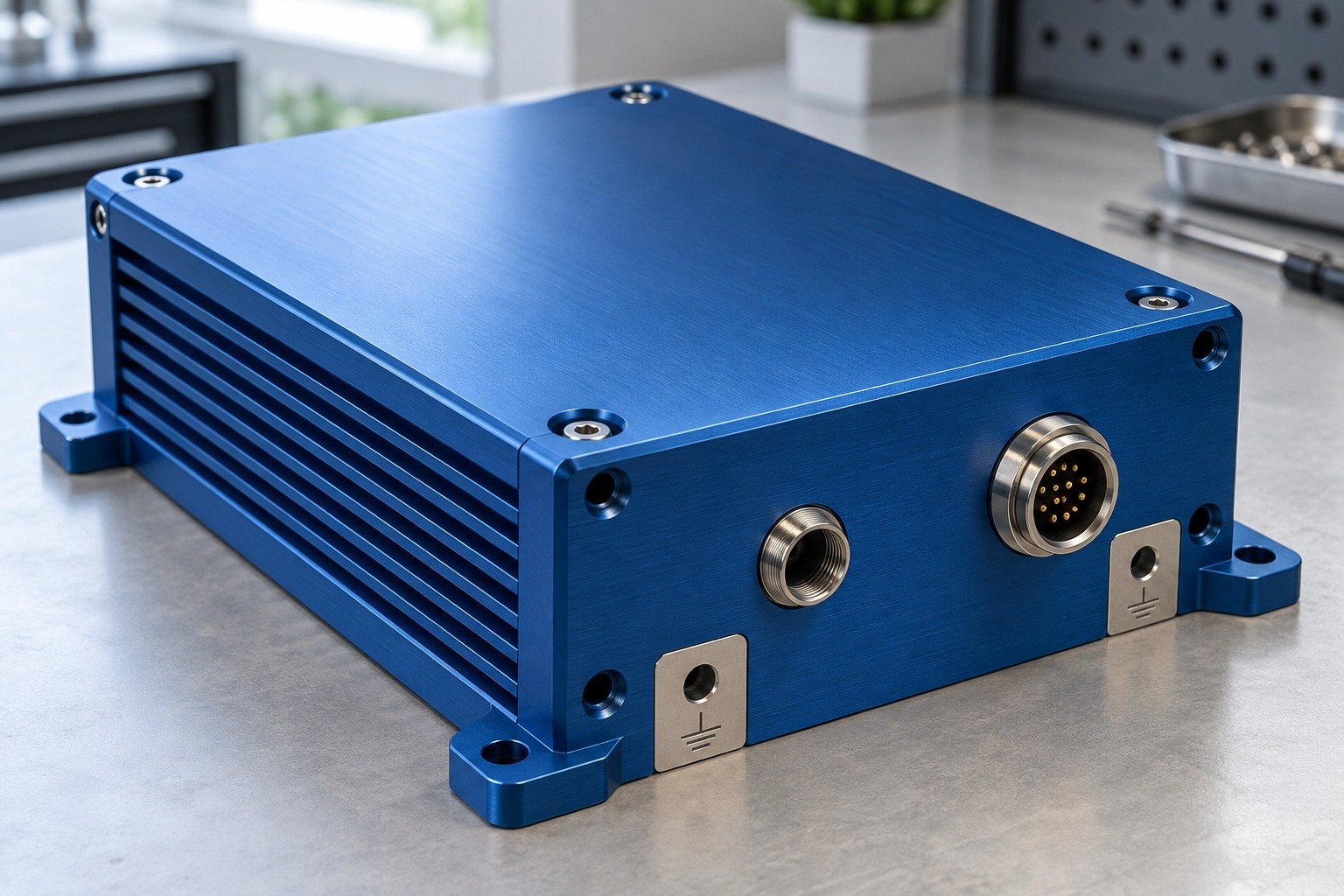
Anodizing for electronics needs defined grounding, fit and visible surfaces.
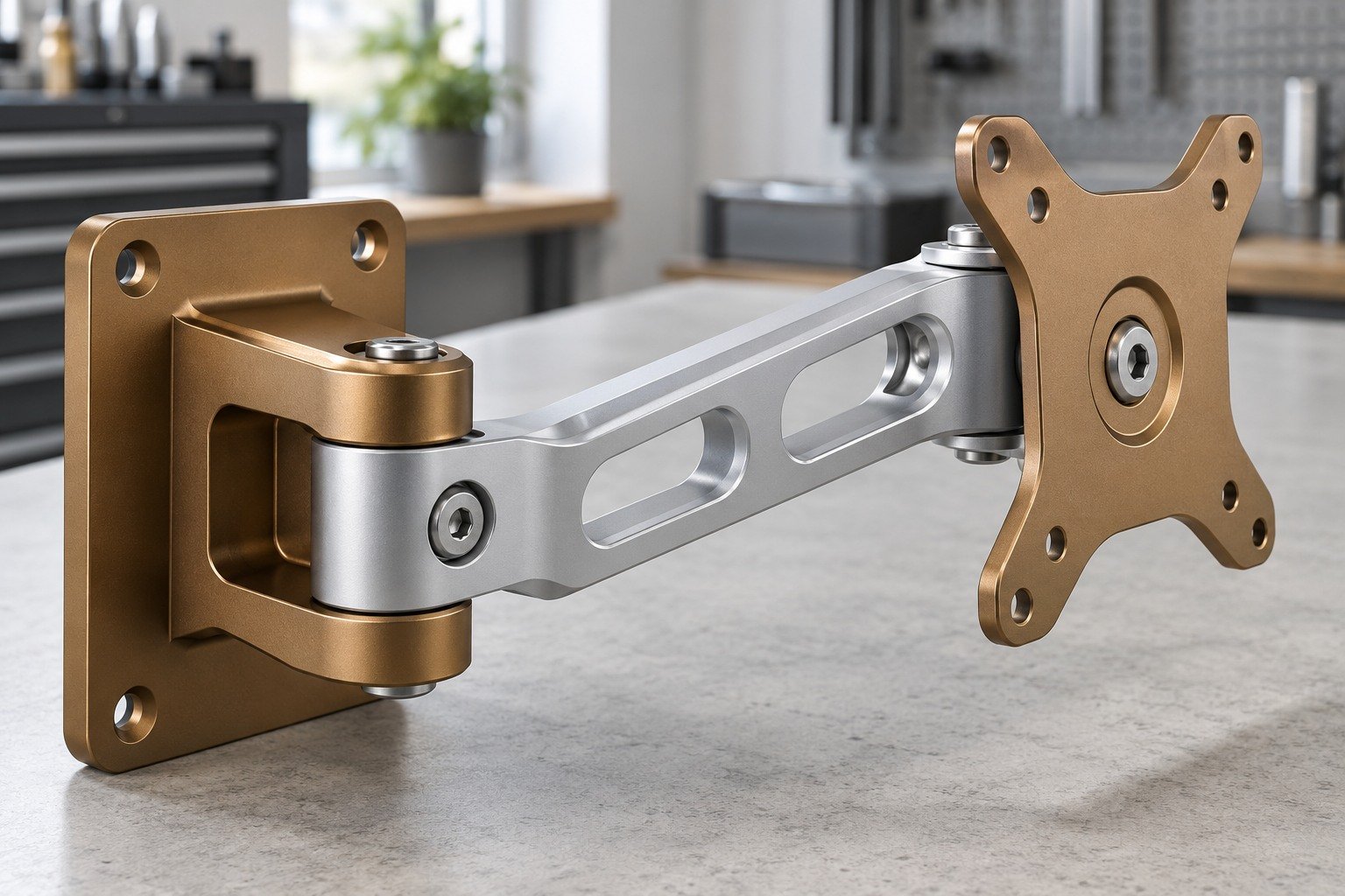
Define mounting interfaces, texture and the approved appearance sample.
Illustrative application concepts. Suitability and required evidence are project-specific; these are not customer case studies or qualification claims.
Coordinate your drawing review, finish samples and delivery requirements.

Project communication and coordination.
Scope and processor confirmed in your quotation.
Agree inspection and release documents.
Confirm protection, schedule and logistics.
For CNC machining and anodizing, identify the responsible scope for machining allowance, finishing and final acceptance.
Anodizing is an electrochemical conversion of the aluminum surface into an anodic oxide layer. It differs from paint and deposited metal plating. Choose the finish around the exact alloy, service environment, appearance and final fit.
Type II is commonly considered for protective and decorative finishes; Type III is a hardcoat route for wear-focused requirements. Specify thickness, sealing, appearance and tests. Actual availability and compliance with your complete specification must be confirmed before ordering.
Yes. Surface conversion and outward growth affect mating dimensions. Define finished limits, required thickness and measurement method. Review machining allowance and masking separately for tight bores, threads and locating faces; do not apply one universal growth ratio.
Agree the alloy, pretreatment, texture and a representative physical color sample, including permitted variation and viewing conditions. Draw mask boundaries for contacts, threads and critical fits; confirm feasible methods and allowable rack marks.
Cost depends on part size, alloy, incoming surface, finish type, quantity, racking, masking, sample work and inspection. Small batch anodizing can carry a minimum processing charge. Request your actual trial and production quantities; no universal minimum is stated here.
Confirm separate milestones for preparation, sample approval, processing, inspection and delivery. Material condition, required masks, special tests, batch scheduling and any machining affect the actual quotation schedule.
Compare substrate, exposure, appearance, electrical requirements, wear and finished fit. Anodizing converts the aluminum surface; powder coating applies a polymer coating; plating deposits another material. Review the complete finishing system rather than treating these routes as interchangeable.
Machining after anodizing removes the finish locally. Agree whether exposed areas are acceptable or need further treatment. Your drawing should identify alloy/condition, finish specification and revision, thickness, color, seal, masks, rack-contact zones, final dimensions and acceptance records.
Finish callout, masks and final dimensions.
Actual texture, color and assembly fit.
Processor, acceptance evidence and delivery terms.
Confirm these together before releasing repeat production.