






































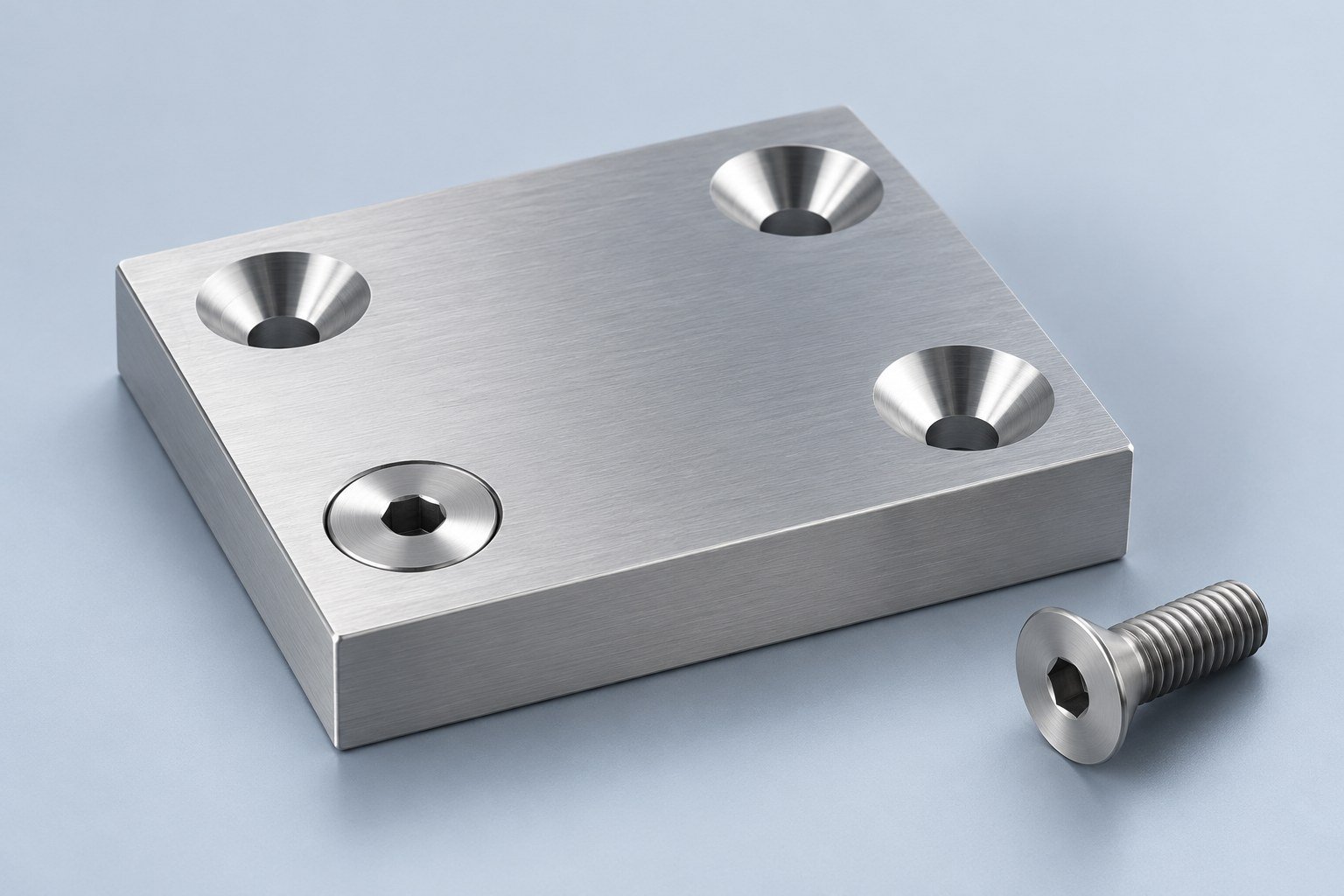
A countersunk hole gives a flat-head fastener a conical seat. For your part, the useful question is whether the selected screw will sit at the intended height, with enough material supporting its head. A hole that looks correct in CAD can still need clarification if the drawing leaves out the angle, diameter, seating side or finish condition.
This guide explains the decisions to include in your drawing and RFQ. It is a design-review aid; your approved fastener specification and drawing control the manufactured feature.
What is a countersunk hole?
A countersunk hole has a conical enlargement at its opening. The cone provides a seat for a compatible countersunk screw or rivet. A counterbore has a cylindrical recess with a flat bottom. An edge-breaking chamfer may also look conical, but a general deburring note does not fully define a fastener seat.
| Feature | Seat shape | What your drawing should clarify |
|---|---|---|
| Countersink | Conical | Hole diameter, major diameter, included angle and seating side |
| Counterbore | Flat bottom with cylindrical walls | Hole diameter, recess diameter and recess depth |
| Edge break | Small chamfer or radius | Permitted edge condition; do not assume it also defines a screw seat |
Match the included angle to your fastener
The countersink angle is the full included angle of the cone. Common tooling includes 82° and 90° options. Tool manufacturer Thürmer identifies 90° with common metric countersunk screws and 82° with common inch countersunk screws. Treat that as a starting point, then verify the actual fastener specification. Special fasteners can require a different angle.
Do not select the angle from the thread diameter alone. Give your manufacturing team the screw designation or supplier drawing, along with any coating or special head requirement. An angle mismatch changes how the head contacts the seat; increasing the diameter alone does not establish compatible seating.
Define the hole with a complete drawing callout
Your CAD model communicates shape, while the controlled drawing communicates the dimensions and acceptance requirements. Include:
- The clearance-hole diameter and whether the hole is through or blind.
- The countersink major diameter and full included angle, with the applicable tolerances.
- The face receiving the countersink, especially when either side could be interpreted as the entry face.
- The number and locations of matching features.
- The required head position: flush, below the surface or another specified condition.
- The material, finish and whether acceptance applies before or after that finish.
A schematic note such as “⌀6.6 THRU; countersink ⌀12 × 90°, this face” illustrates the pieces of information. Those example dimensions are not a recommendation for a particular screw. Choose values from your actual fastener, stack-up and engineering requirements. Follow your drawing standard for symbols and presentation.
Use depth calculations as a geometry check
For an ideal conical seat, let D be the major diameter, d the cylindrical hole diameter and θ the full included angle. The axial height of the conical enlargement is:
h = (D − d) / [2 × tan(θ / 2)]
For example, with D = 12 mm, d = 6.6 mm and θ = 90°, h = 2.7 mm. This is a geometric illustration, not a cutter-depth setting or a guaranteed fastener fit. A cutter tip flat, a fastener’s head geometry, edge breaks and surface finish can affect the real result. Keep the drawing’s defining dimensions authoritative instead of adding conflicting diameter and depth requirements.
Check remaining material and nearby features
Compare the conical-seat geometry with the local wall thickness. If the seat approaches the opposite face, review the remaining support and any risk of breakthrough with your engineer. Thin sheet may need a different fastener or a formed feature rather than a deep machined countersink. These alternatives require approval; they are not interchangeable manufacturing substitutions.
Also review edge distance, adjacent holes, bends, pockets and the access needed for the tool and fastener. A clear top view alone may hide a conflict with a pocket on the reverse side. A section view can make that relationship easier to inspect.
Agree how the seat will be checked
Inspection should follow the drawing’s acceptance criteria. Major diameter, included angle and location describe different aspects of the feature. A sample screw can help demonstrate assembly seating when that check is agreed, but it does not independently verify every dimensional requirement.
For a functional first article, identify the actual fastener and mating stack used for review. Specify whether flushness is checked after coating, and define any permitted recess or protrusion. If surface damage, burrs or chatter marks would affect the assembly, make the required surface condition clear before production.
What to include in your countersunk-part RFQ
Send the current CAD model and drawing revision, material and finish, initial and repeat quantities, fastener specification, and the critical seating and inspection requirements. Highlight unresolved choices rather than leaving your supplier to infer them. That gives your team a clearer basis for comparing quotations and approving the first build.
For related review inputs, see the CNC machining RFQ checklist and CNC machining service overview.
Questions to resolve before release
Is a countersink the same as a chamfer?
A countersink can be produced with a conical cutting tool, but its role here is a specified fastener seat. A general chamfer or edge-break note should not be assumed to define that seat’s diameter, angle and head position.
Can I choose 82° or 90° by appearance?
No. Check the fastener specification and the required included angle. Similar-looking heads and tools are not evidence that their angles match.
Does flush seating prove that the whole hole is correct?
No. Seating is one functional check. Your drawing may also require dimensional verification of diameter, angle, location and other features.
Technical references
- Thürmer Tools: drill and countersink selection FAQ — common angle conventions; verify your actual fastener.
- Haas Tooling: example 82° countersink — an example of angle-specific tooling, not a universal cutting recommendation.

