Manufacturing Insights · DFM & Design
Injection Molding DFM Checklist for Buyers and Engineers
Six drawing and CAD checks to review before you approve an injection mold.
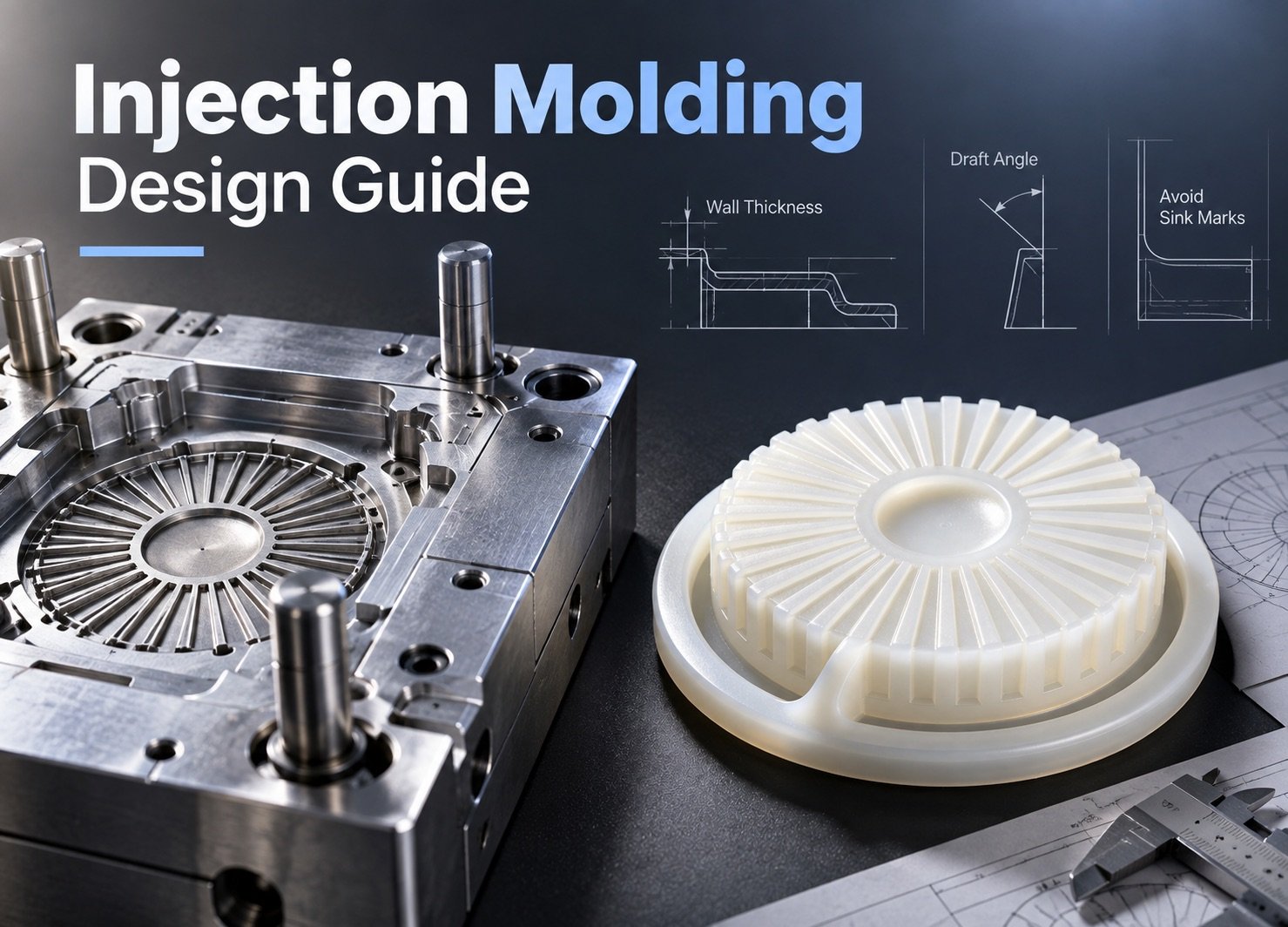
- Mark the critical mating and cosmetic surfaces.
- Review resin, part design and tooling together.
- Send matching CAD and drawing revisions for the quote.
Six design checks before tooling approval
1. Wall thickness
Review thick intersections and abrupt transitions for sink and warpage risk.
2. Ribs
Review the rib base and the transition into the adjoining wall.
3. Bosses
Review the fastener load, boss support and adjacent cosmetic surfaces.
4. Draft
Mark the draw direction and review draft on textured and deep faces.
5. Undercuts
Flag features that prevent straight release. Discuss a geometry change or a side action.
6. Gate location
Discuss the gate witness and keep it away from specified cosmetic or mating surfaces where feasible.
What to send for design review
Provide your CAD model, current drawing, resin specification and planned order volumes. Mark cosmetic zones, mating surfaces and critical inspection dimensions. Ask the toolmaker to review the proposed parting line, gate and ejection before you approve the tool.

Leave a Reply