Manufacturing Standards and Reference Tables
Give your supplier the information needed to quote and inspect your part. Choose a process to see which drawing callouts, sample checks and acceptance records to agree before production.
Request an Engineering-Reviewed Quote
Workmanship Requirements for Your Parts
Define what makes your part acceptable before quoting. Give your supplier the controlled drawing revision, critical features and any required inspection records. Use your agreed sample or appearance specification to resolve cosmetic decisions before the first batch.
Finished surfaces and appearance
Mark visible faces and the viewing conditions you will use to judge them. If color, gloss or texture matters, agree on a sample or specification before production. Specify which faces need masking or protection in transit.
Machined surfaces and tool marks
Identify sealing, bearing and mating surfaces on your drawing. Specify surface roughness where it affects function and agree how it will be checked after finishing.
Burrs, edge breaks and sharp edges
Show which edges need deburring or an edge break. Call out edges that must remain sharp or retain a functional profile. Check the result where the part contacts a seal, harness or installer.
Cleanliness and handling
State whether chips, process residue or contamination would interfere with assembly. Agree any cleaning, protection and packaging requirements and record the check before lot release.
Before you send your RFQ
Which features will you measure, what record do you need, and who can release the lot?
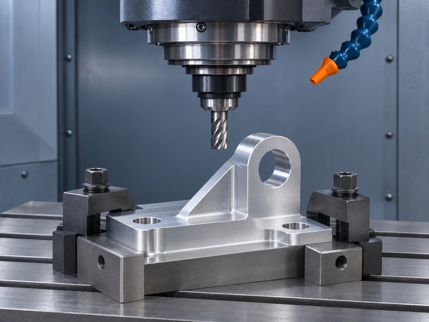
CNC machining and turning
For CNC milling or turning, mark the locating faces, bores and fastener interfaces that govern fit. Identify where surface roughness, burr removal or an edge break affects function, and specify the inspection stage if finishing changes a mating surface.
Confirm before you approve
Can the supplier measure the agreed characteristics from the same reference features shown on your drawing?
Learn more about cnc machining and turning
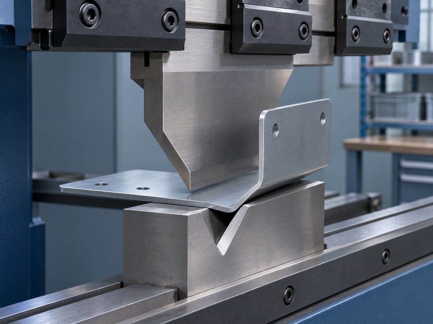
Sheet cutting and fabrication
For a formed bracket or panel, send the finished geometry with the material grade and thickness. Call out bend angles, flange lengths and holes whose position matters after forming. Identify visible faces and specify how to handle sharp cut edges.
Confirm before you approve
Will you approve dimensions on the finished formed part, and what changes require a fresh sample?
Learn more about sheet cutting and fabrication
Die casting
On a cast part, separate the surfaces that stay as cast from those that are machined or coated. Mark the mounting and sealing features that control assembly. Agree which surfaces may show gate, parting line or ejector evidence and what test is needed if porosity could affect function.
Confirm before you approve
Which features are accepted as cast, and which must be checked again after machining or coating?
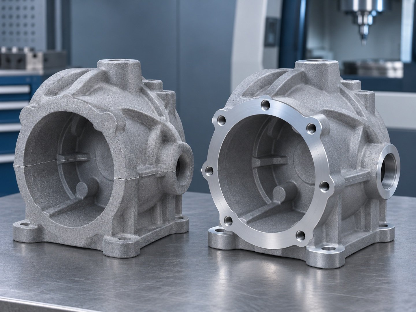
Learn more about die casting
Plastic injection molding
Specify your resin grade, color and appearance requirements before reviewing the mold layout. Agree where gates, parting lines and ejector marks may sit. Identify mating features and the conditions for checking dimensions on approved samples.
Confirm before you approve
What changes to material, tooling or process require a new sample review?
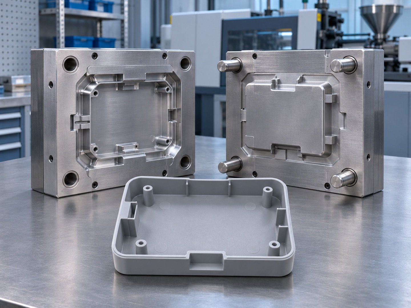
Learn more about plastic injection molding
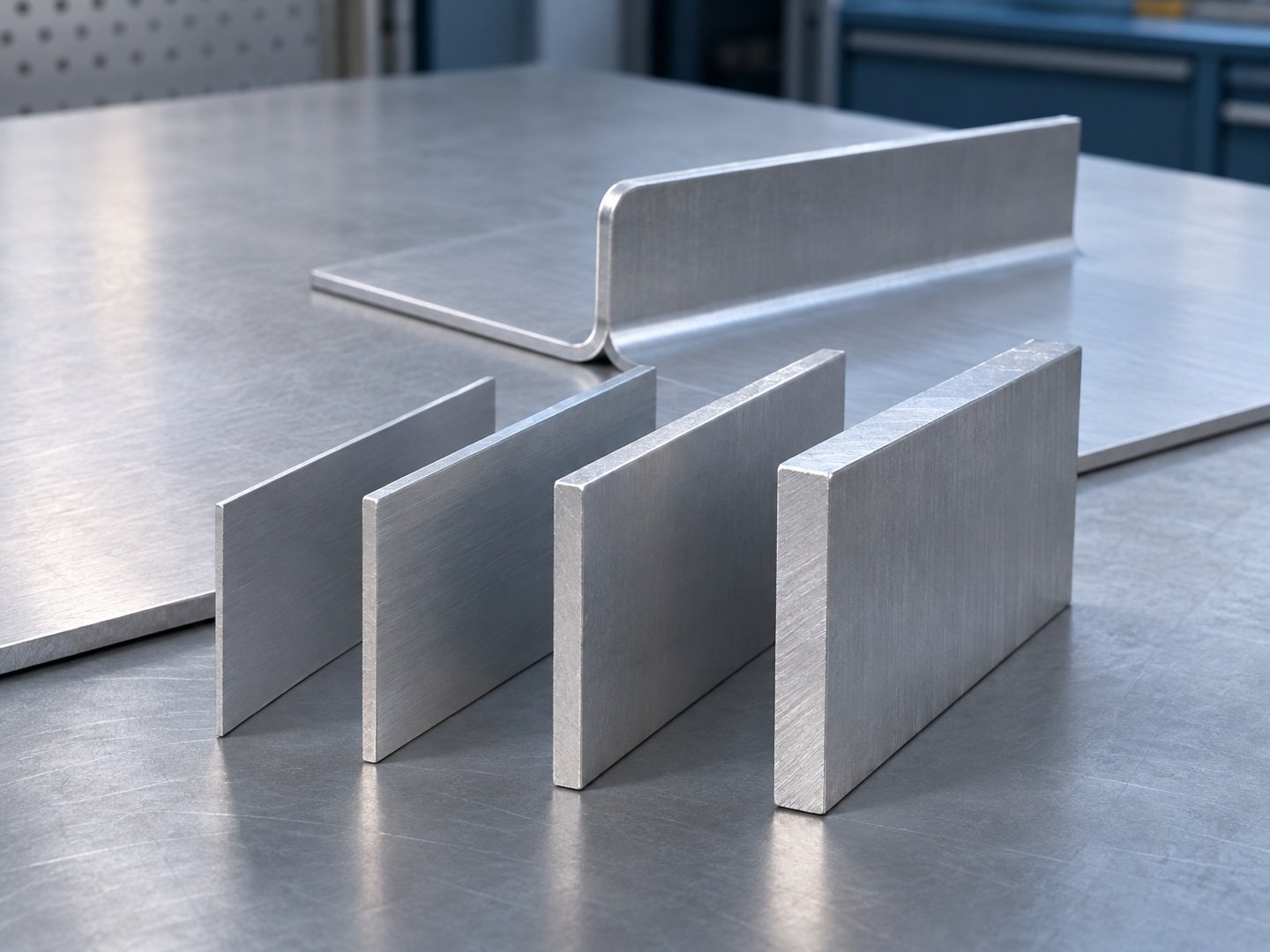
Specify sheet metal thickness for your part
Write your sheet metal thickness in a controlling unit and state the material grade and temper where relevant. Use the conversions below to compare quotes. Where thickness affects fit, define the acceptable range and review how any proposed stock change affects the formed part.
| Inches | Millimeters |
|---|---|
| 0.040 | 1.016 |
| 0.060 | 1.524 |
| 0.125 | 3.175 |
Examples use 25.4 mm per inch. Confirm material availability and thickness tolerance for your order.
Before you send your RFQ
What nominal thickness and tolerance should the supplier use for your part?
Define tube size for your assembly
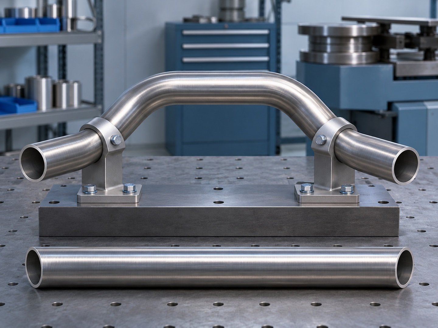
On a bent tube assembly, show outside dimensions, wall thickness and material grade. Specify centerline radius, bend angle and end positions from the mounting features. If the part clamps or fits into another tube, identify the functional fit after bending.
Before you send your RFQ
Which tube ends or interfaces must line up on your first assembly sample?
Confirm threads and inserts for your hardware
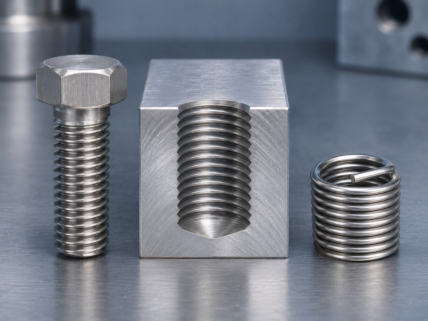
Call out diameter, pitch, thread form and required usable engagement. Specify through or blind holes and the applicable fit class. If your design uses a threaded insert, identify the insert type or part number and the required installation depth.
Before you send your RFQ
Which mating fastener should be checked, and how will you verify engagement after finishing?
Send the files your supplier needs to quote
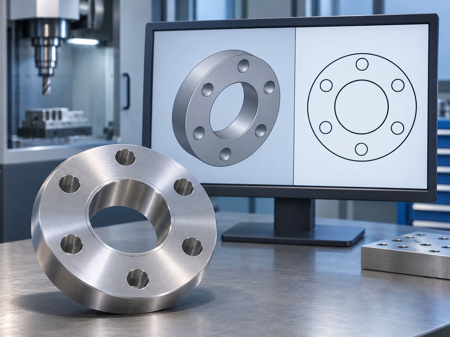
For your CNC machining RFQ, send the CAD model and controlled PDF drawing at the same revision. Show the critical bore, hole pattern or mating surfaces, and state quantity, finish and inspection requirements. Identify the controlling document if the files disagree.
Before you send your RFQ
Can the supplier identify the features to quote and inspect from the files you send?
Prepare your quote and approval plan
Before the first production batch ships, match the lot to the approved drawing, review any open deviations and record who can release it. Use the first production batch approval checklist to document the decision.
Request an engineering review