Injection Molding
Tooling and molding for your repeat plastic parts.
From prototype to production, coordinated manufacturing solutions for your custom parts.
View All Services →
Precision parts for your tight tolerances and complex geometry.
Tooling and molding for your repeat plastic parts.

Metal casting options for your part and production volume.

Cutting, forming and welding for your fabricated parts.

Custom profiles for your section, length and finish requirements.

Finishes for your appearance, corrosion and wear requirements.

Sub-assemblies and final builds for your production program.

Production tooling built around your process and volume.

Prototype parts to check fit, function and design.
DFM, process planning and production support for your project.
Inspection, documentation, inventory and delivery planning for your program.
Choose air- or liquid-cooling components around your thermal and mechanical requirements.

Manufacturing support for your cold plates, manifolds and cooling assemblies.

Find components for your power electronics, energy, laser and telecom application.

Components for your electronic systems.
Start with your functional and quality requirements.
Build around your operating environment.
From prototype to production, review material performance, manufacturability and cost for your part.
Review grade, temper and finish for your metal parts.
 AluminumStrength, weight and machining›
 Stainless SteelCorrosion and finish requirements›
 Carbon & Alloy SteelDiscuss grade and heat treatment›
 Tool SteelDiscuss tooling and wear needs›
 TitaniumReview grade and part geometry›
 Copper & Brass & BronzeDiscuss conductivity and machining›
Match your polymer to function, process and environment.
 ABSReview enclosure and molding needs›
 Polycarbonate (PC)Discuss clarity and impact needs›
 Nylon (PA)Review moisture and wear conditions›
 POM / AcetalReview fit and sliding features›
 PEEKDiscuss operating conditions›
 PTFEReview friction and chemical exposure›
 ULTEM / PEIDiscuss thermal and electrical needs›
Confirm grade availability and application requirements.
 Silicone / LSRDiscuss flexible component needs›
 TPU / TPEReview flexibility and processing›
 EPDMReview weathering and chemical exposure.›
 NBRReview oil and fuel exposure.›
 FKMReview temperature and chemical exposure.›
 G10 / FR4Review insulation and laminate needs›
 CompositesReview stiffness, weight and laminate.›Customer-Specified MaterialsConfirm your grade and requirements.›Other Specialty MaterialsDiscuss your application and grade.›
Practical guidance for your part geometry and material decisions.
Prepare your process, budget and sourcing questions.
Build your knowledge before production.
Learn who we are and how we operate.
Find our U.S. support team or start a conversation.
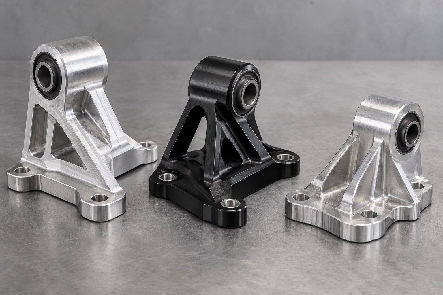
For your engine-swap or performance-parts program, define CNC engine mount brackets around the retained engine, chassis and isolator interfaces. Bring mounting datums, load inputs, final bores and clearance requirements into the manufacturing review.
Datums and bolt locations
Bushing and sleeve references
Loads and clearance envelope
Fits, finish and records
Made-to-drawing mechanical components · Define installed-system validation separately
Identify the component to manufacture and the retained assembly it must fit.
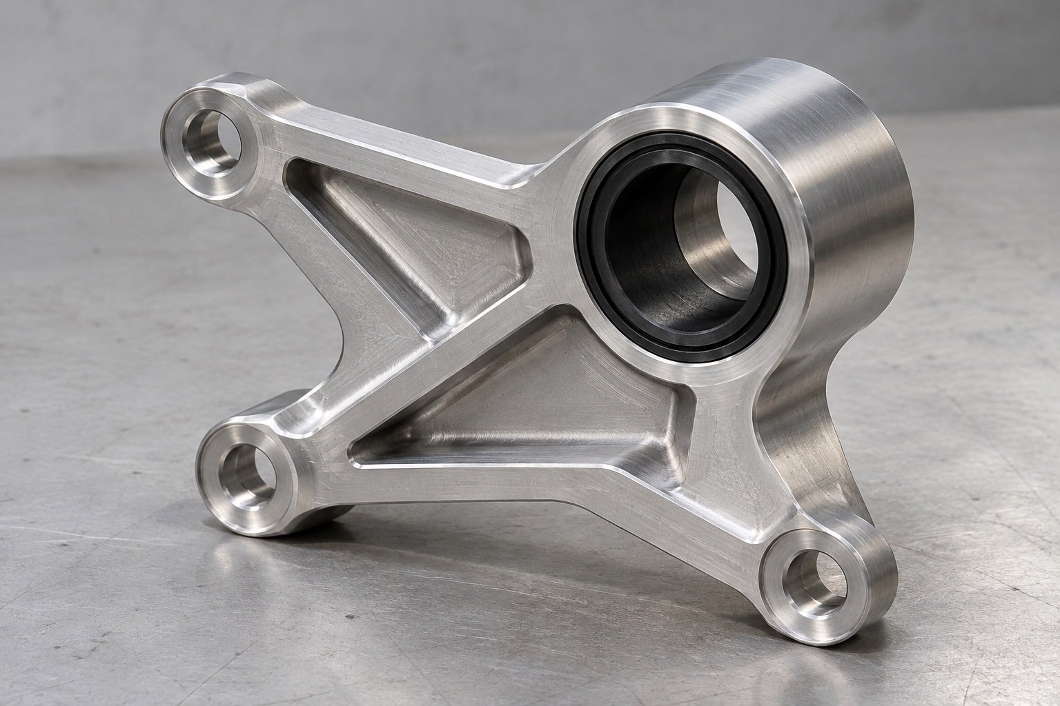
Locate fixing holes, mounting faces and bushing bores from your controlled engine references.
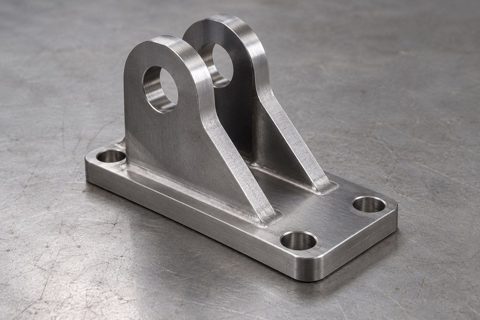
Define ear spacing, aligned bores, mounting feet and the surrounding clearance envelope.
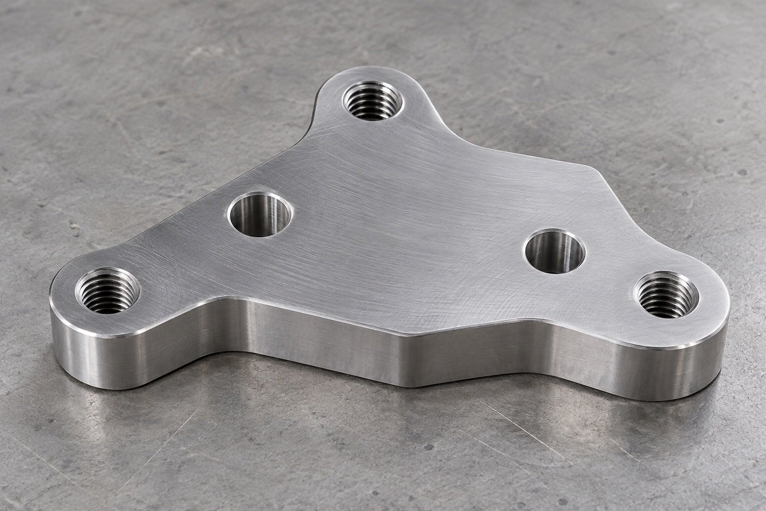
Connect retained interfaces with defined datums, hole patterns and final contact faces.
An engine or chassis model name does not replace a released component drawing.
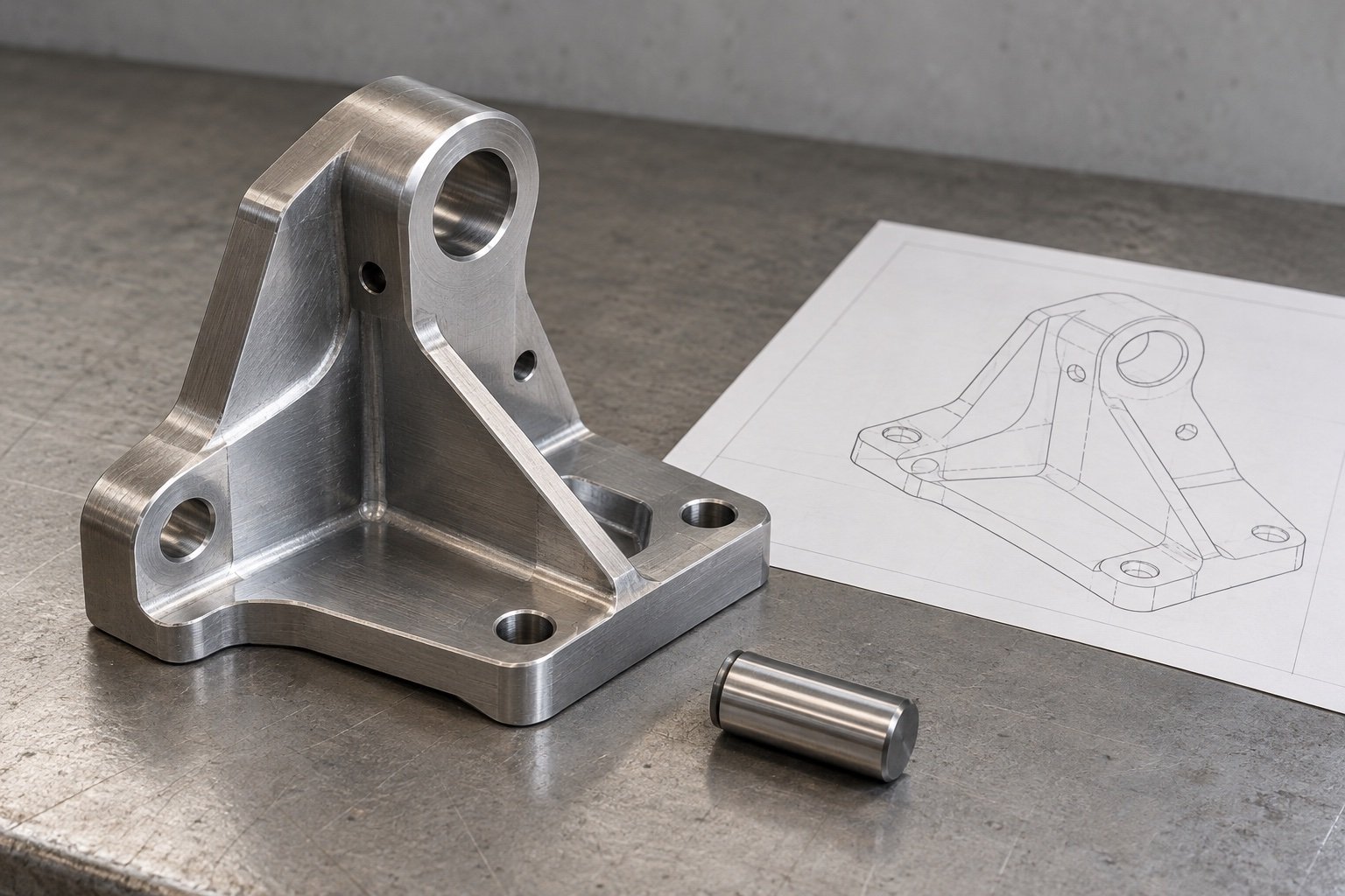
Provide engine and chassis mounting references and the specified isolator or bushing details.
Mark datums, bore positions, ear spacing, fastener access and mating faces.
Supply drawing-defined loads, temperature exposure, movement envelope and validation requirements.
State material condition, finish, quantities, required records and target date.
Connect tool access to the interfaces that locate the assembly.
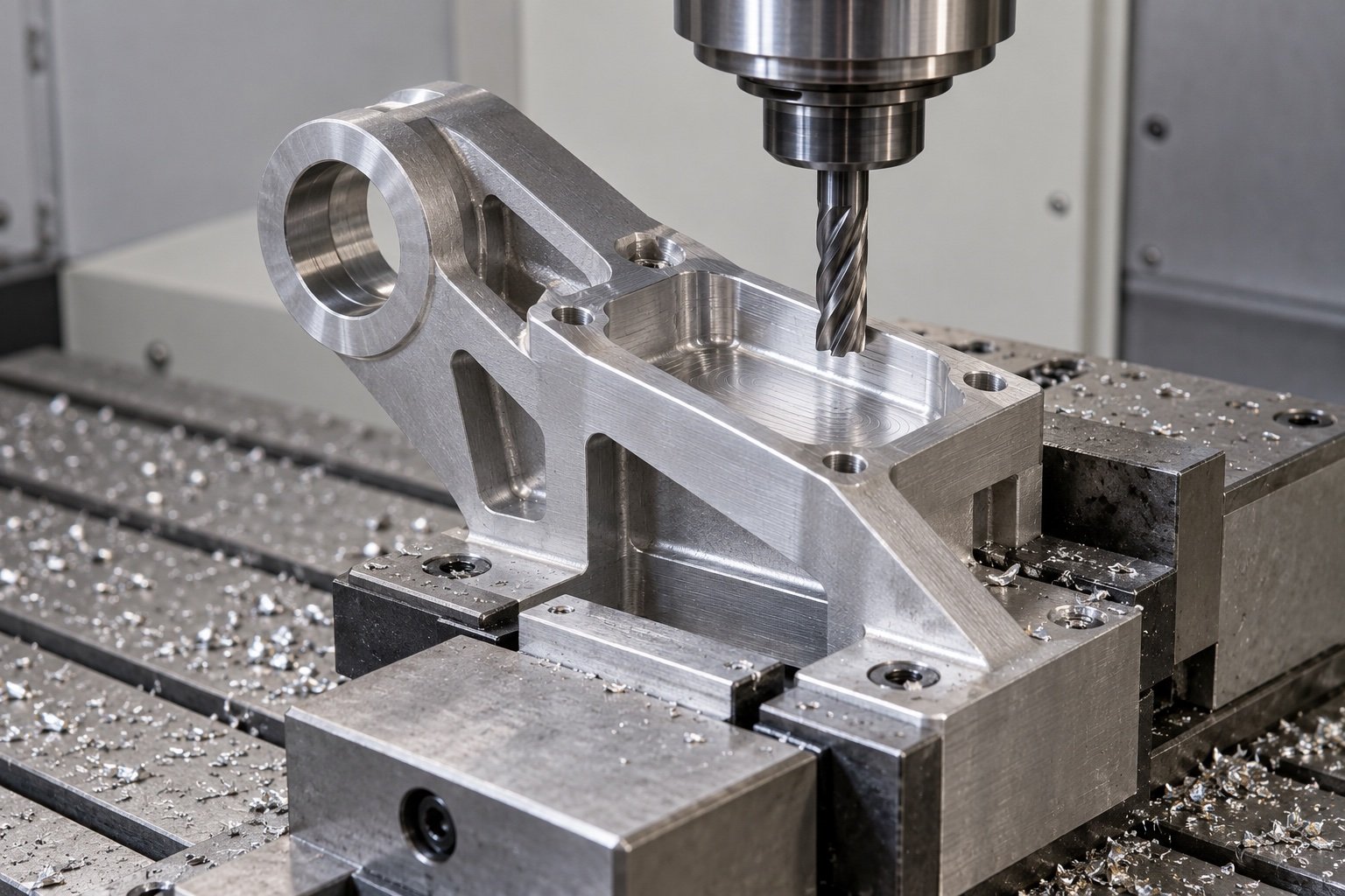
Review accessible mounting faces and how bores relate to the approved datum scheme.
Identify required ribs, internal radii and sections without promising strength from appearance.
Define bushing fits, finished dimensions and coating masks before sample machining.
Your grade and isolator specification serve different functions in the assembly.
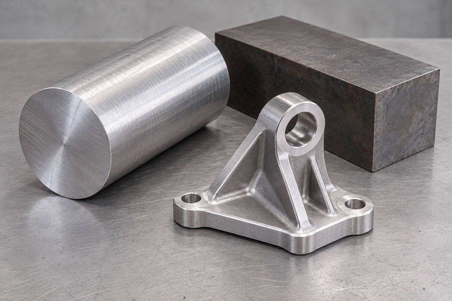
Provide grade, temper or heat treatment, stock form and required certificate scope.
Identify the customer-specified isolator, retained sleeve and required fits. Do not infer vibration behavior from the bracket alone.
Agree corrosion exposure and protected fits. EN AW-6061 and EN AW-7075 are material references, not substitution approval.
Review the manufactured component and the installed assembly as separate acceptance scopes.
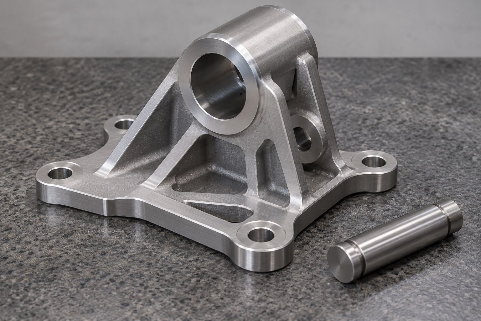
Check fixing-hole locations and face relationships against the released drawing.
Report specified bores, ear spacing and sleeve contact dimensions.
Review final fits, protected zones and approved appearance references.
Define who verifies installed clearance, vibration, durability and load cases; no rating follows from a dimensional report.
Keep the approved component definition linked to your assembly references.
Send CAD, drawing, mating references and required quantities.
Confirm alloy, machining, finish, bushing responsibility and inspection requirements.
Check dimensions and assembly fit and complete your required validation.
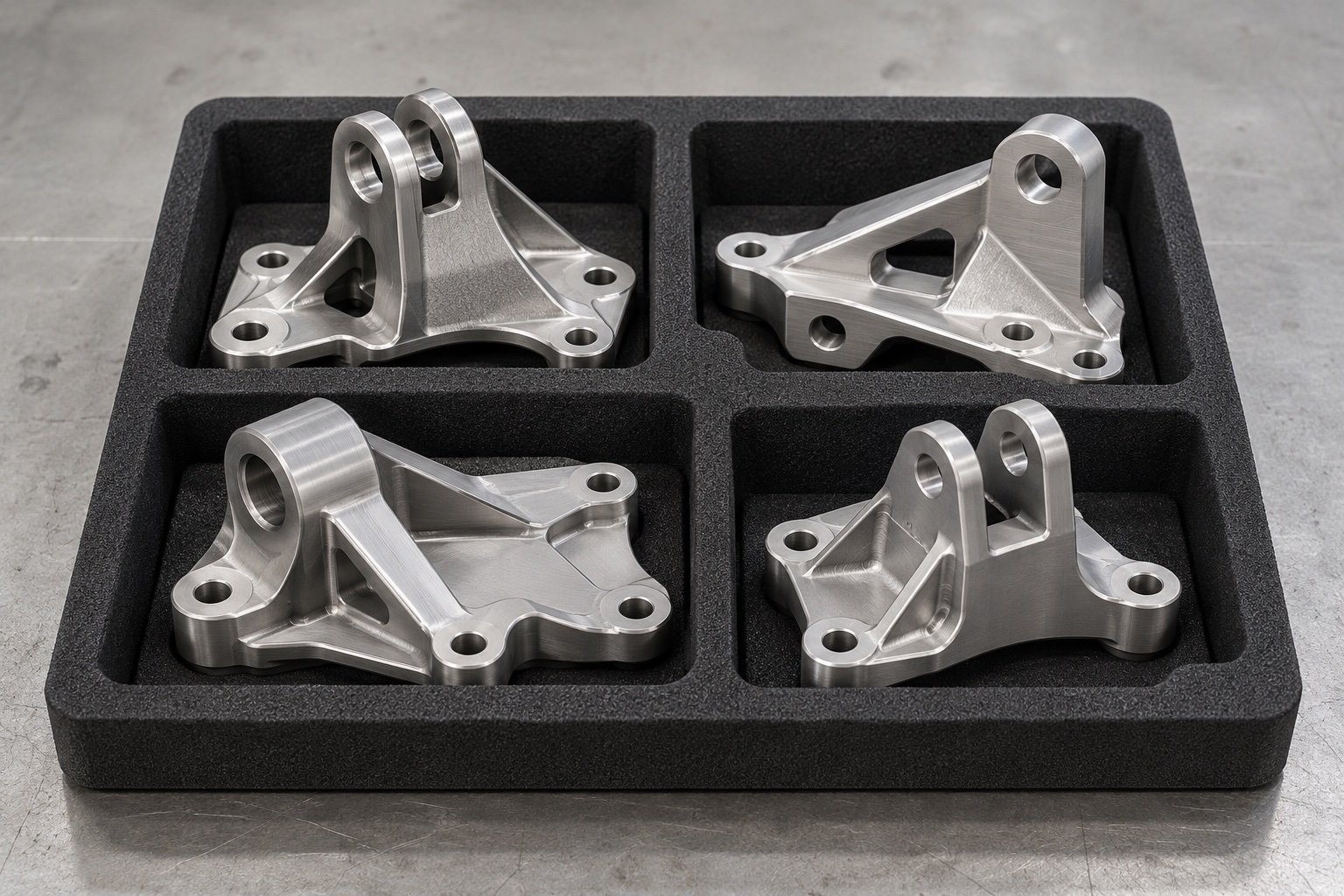
Retain revision, material condition, identification and protective packing instructions.
For your engine mount program, distinguish where the part is made from where your project communication is supported.

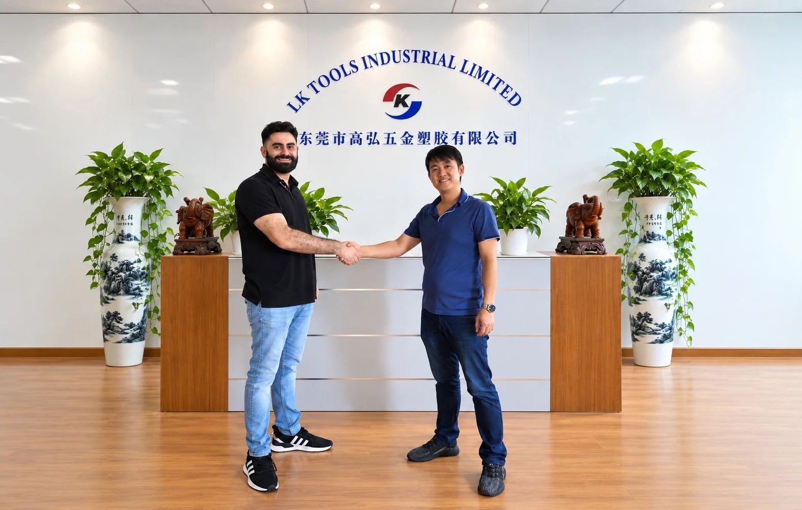

Agree who owns the drawing and sample approval.
Confirm packing, delivery terms and import responsibilities.
Discuss local coordination and any inventory arrangement.
Genuine company and customer-discussion photographs. Manufacturing in China; U.S. support does not mean U.S. manufacture or a default local stock program.
Factory & Operations →Upload the drawing revision, material, finish and quantities. Include mounting datums, bushing references, load inputs, final bores, material condition and required records.
Resolve mounting geometry, isolator responsibilities and acceptance before release.
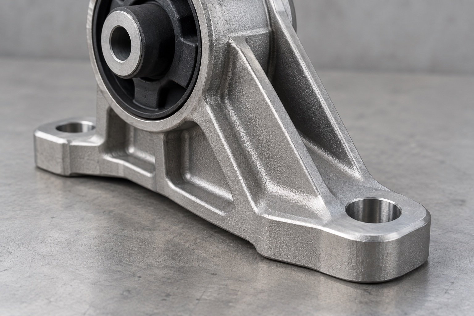
Send CAD, the released drawing, engine and chassis references, bushing specification, critical fits, material condition, quantities and inspection requirements.
Provide the approved isolator and sleeve requirements for your design. Vibration targets and installed-system validation need a defined engineering scope.
A photograph supports the brief but cannot establish hidden dimensions, load requirements or datum relationships. Supply controlled geometry and retained references.
No. Appearance cannot establish fatigue life or load capacity. Provide the design requirements and validation plan for your application.
Define the final fit, coating thickness requirements and masking instructions on the drawing. Agree inspection in the finished condition.
Discuss prototype and repeat quantities together. Preserve the approved revision, material, finish, fit and records for subsequent orders.