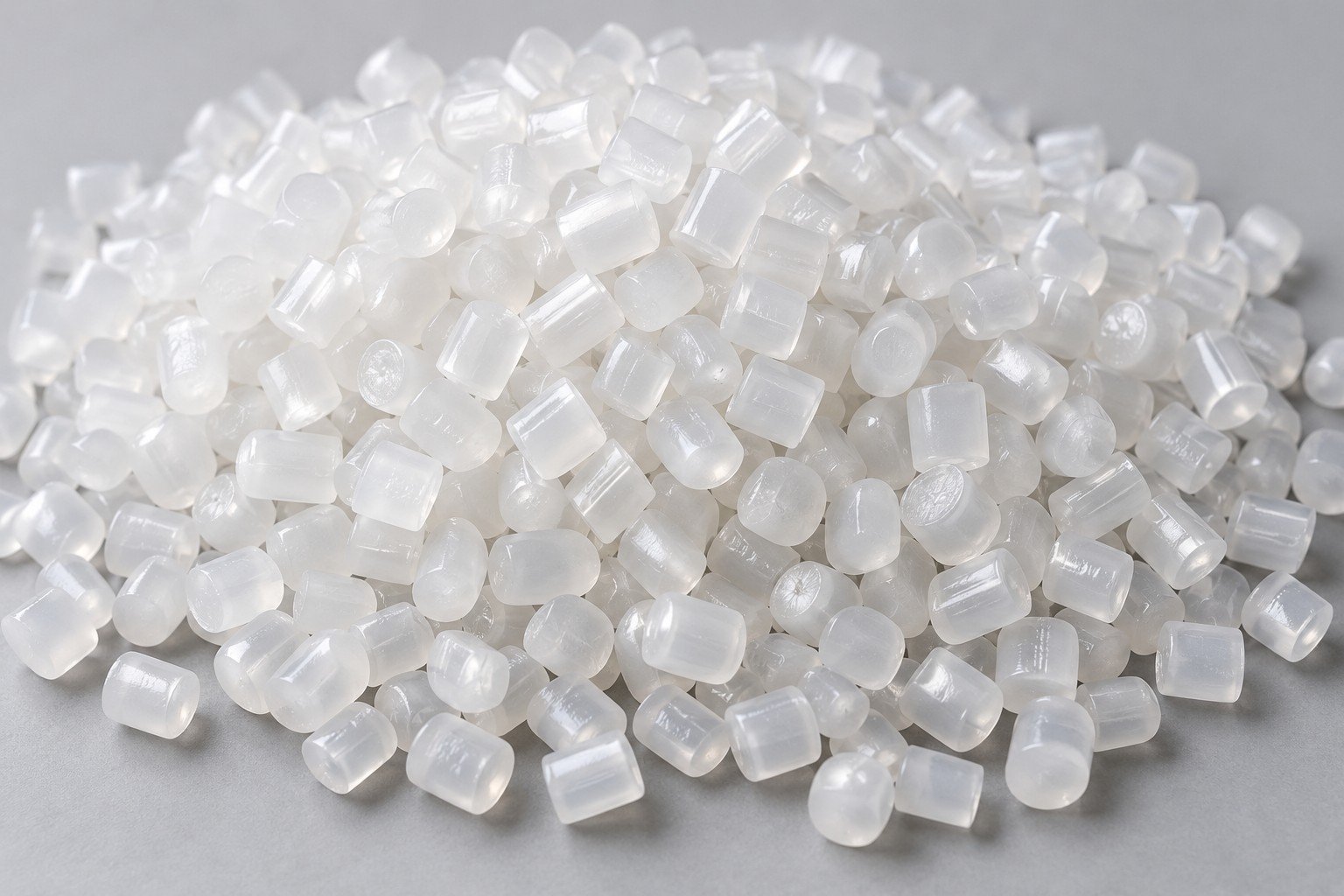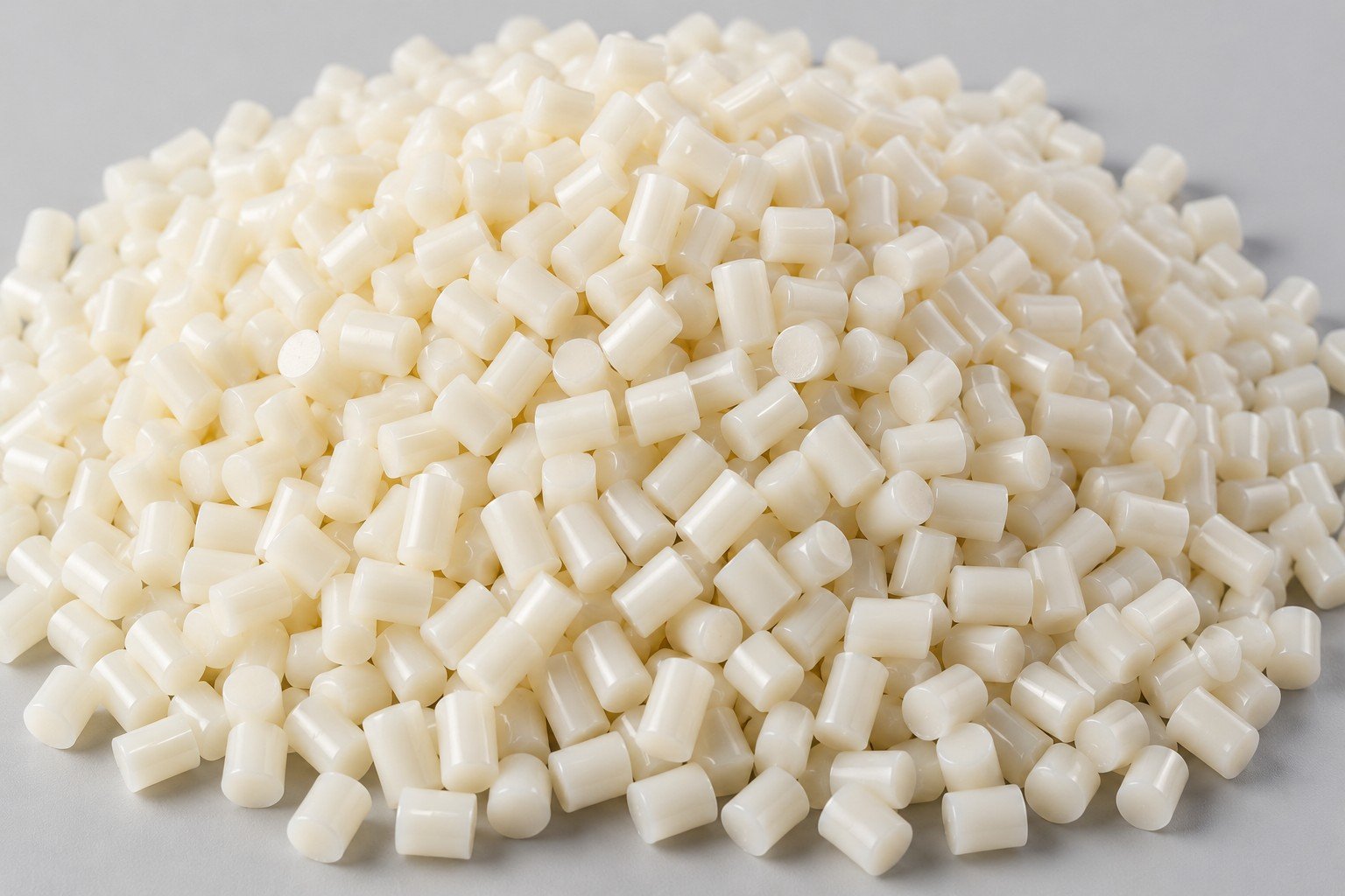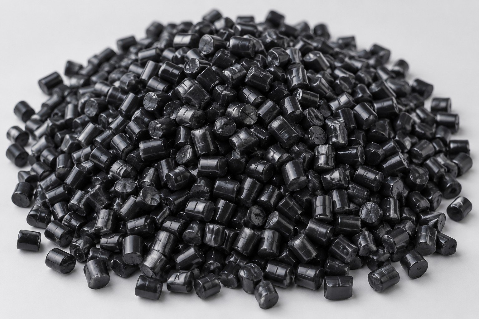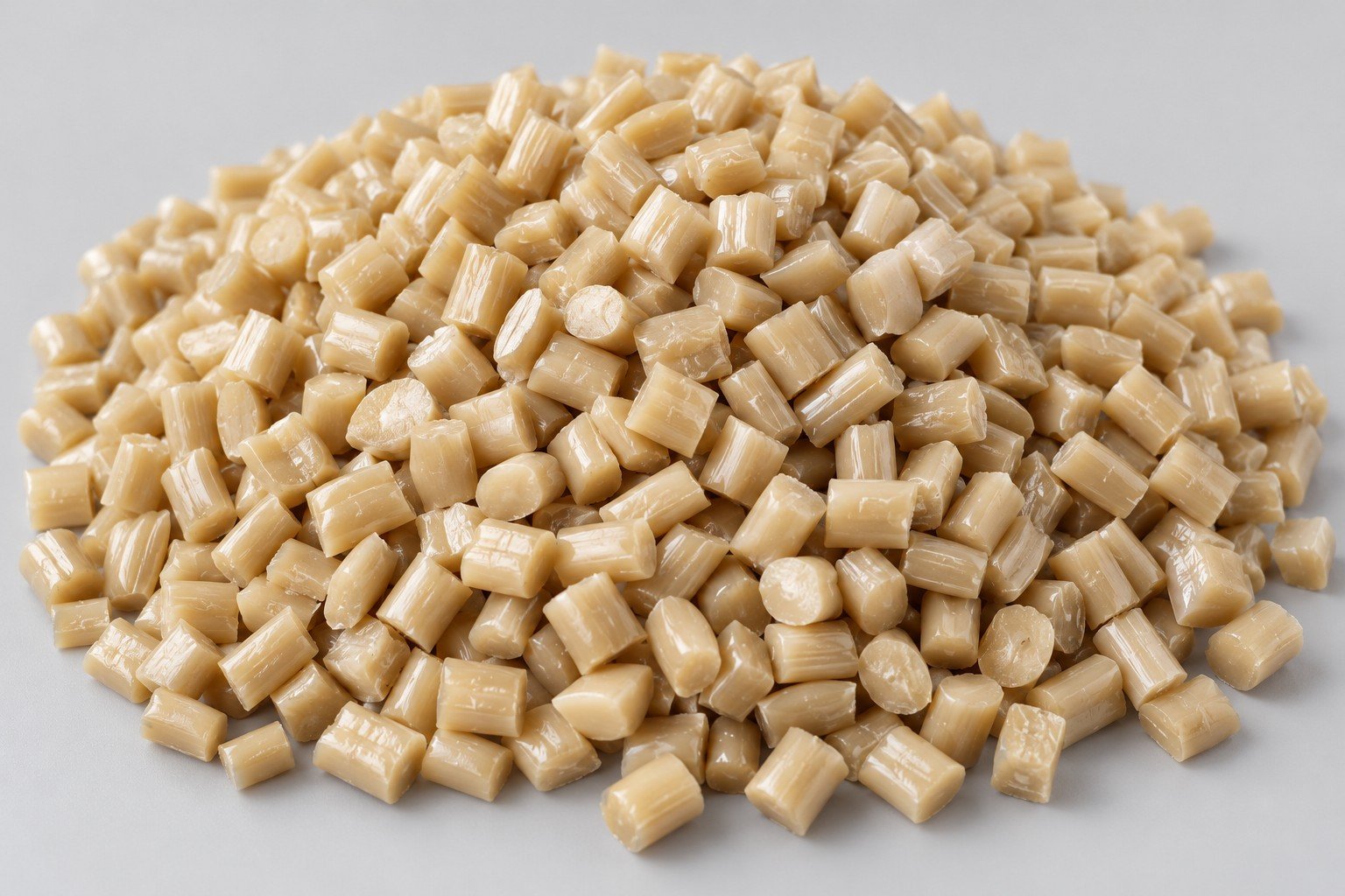
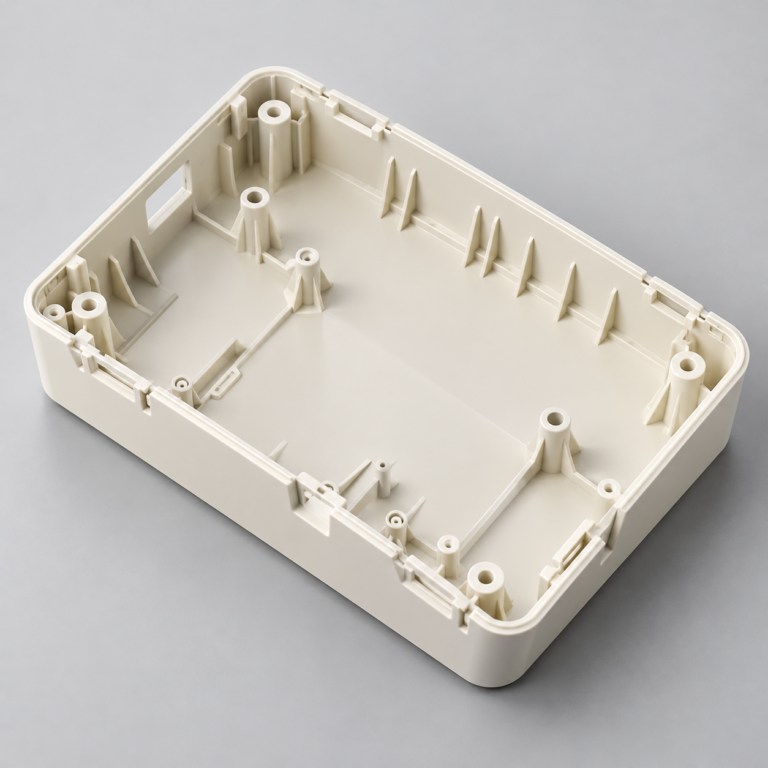
Injection Molding
Tooling and molding for your repeat plastic parts.
From prototype to production, coordinated manufacturing solutions for your custom parts.
View All Services →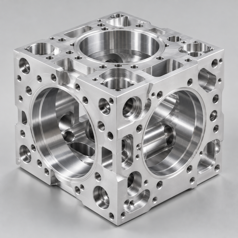
Precision parts for your tight tolerances and complex geometry.
Tooling and molding for your repeat plastic parts.
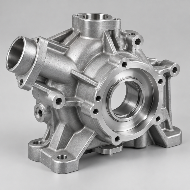
Metal casting options for your part and production volume.
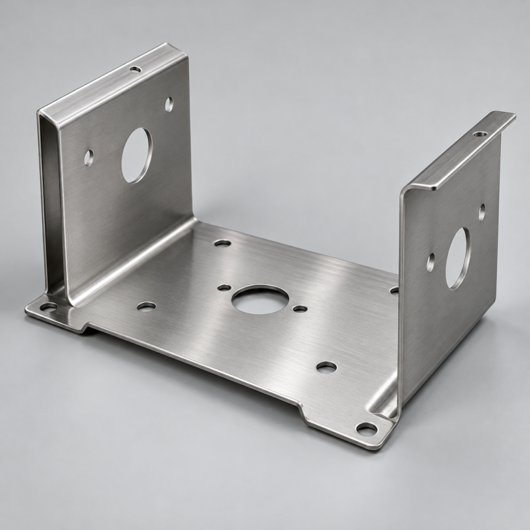
Cutting, forming and welding for your fabricated parts.
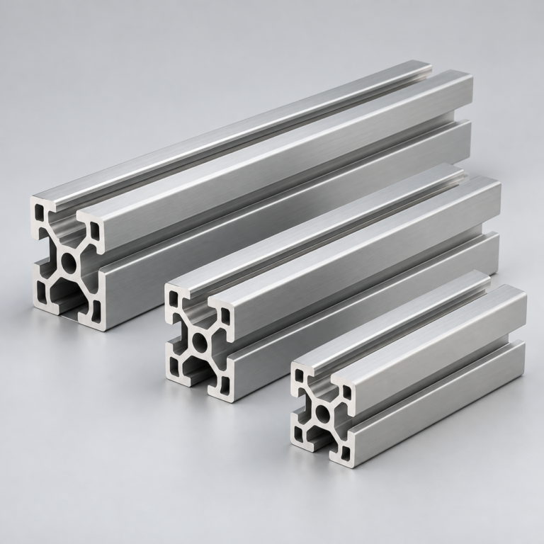
Custom profiles for your section, length and finish requirements.
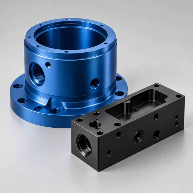
Finishes for your appearance, corrosion and wear requirements.
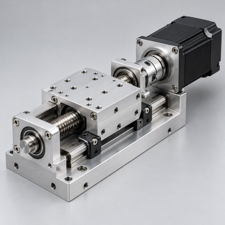
Sub-assemblies and final builds for your production program.
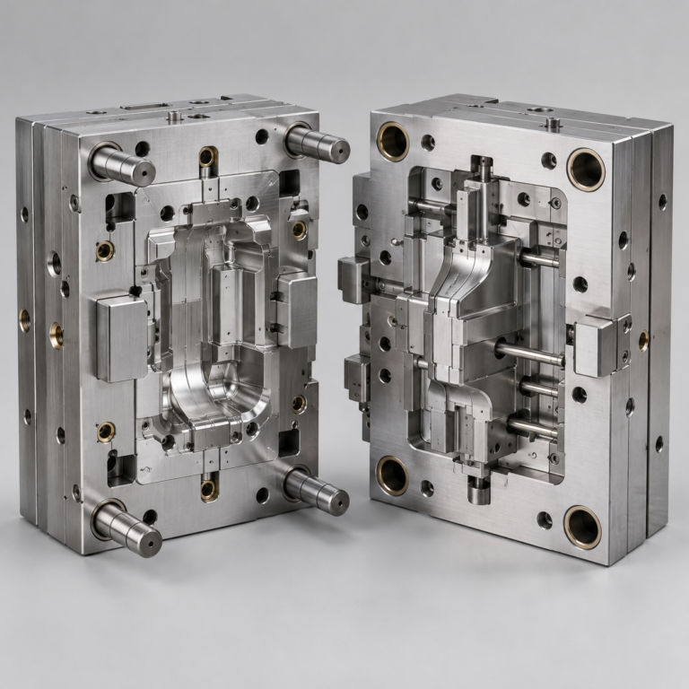
Production tooling built around your process and volume.
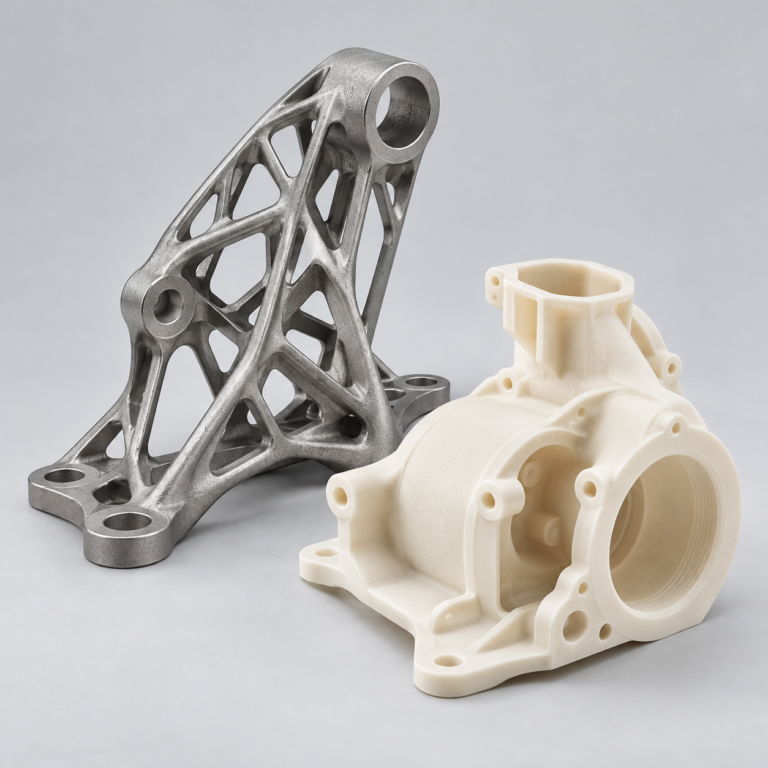
Prototype parts to check fit, function and design.
DFM, process planning and production support for your project.
Inspection, documentation, inventory and delivery planning for your program.
Choose air- or liquid-cooling components around your thermal and mechanical requirements.
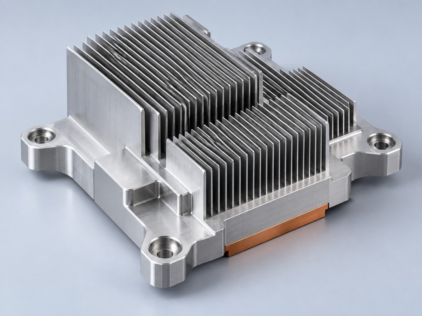
Manufacturing support for your cold plates, manifolds and cooling assemblies.
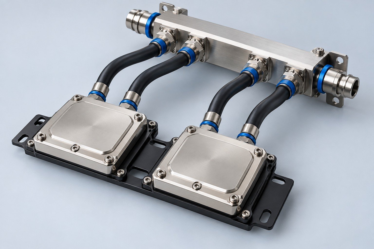
Find components for your power electronics, energy, laser and telecom application.
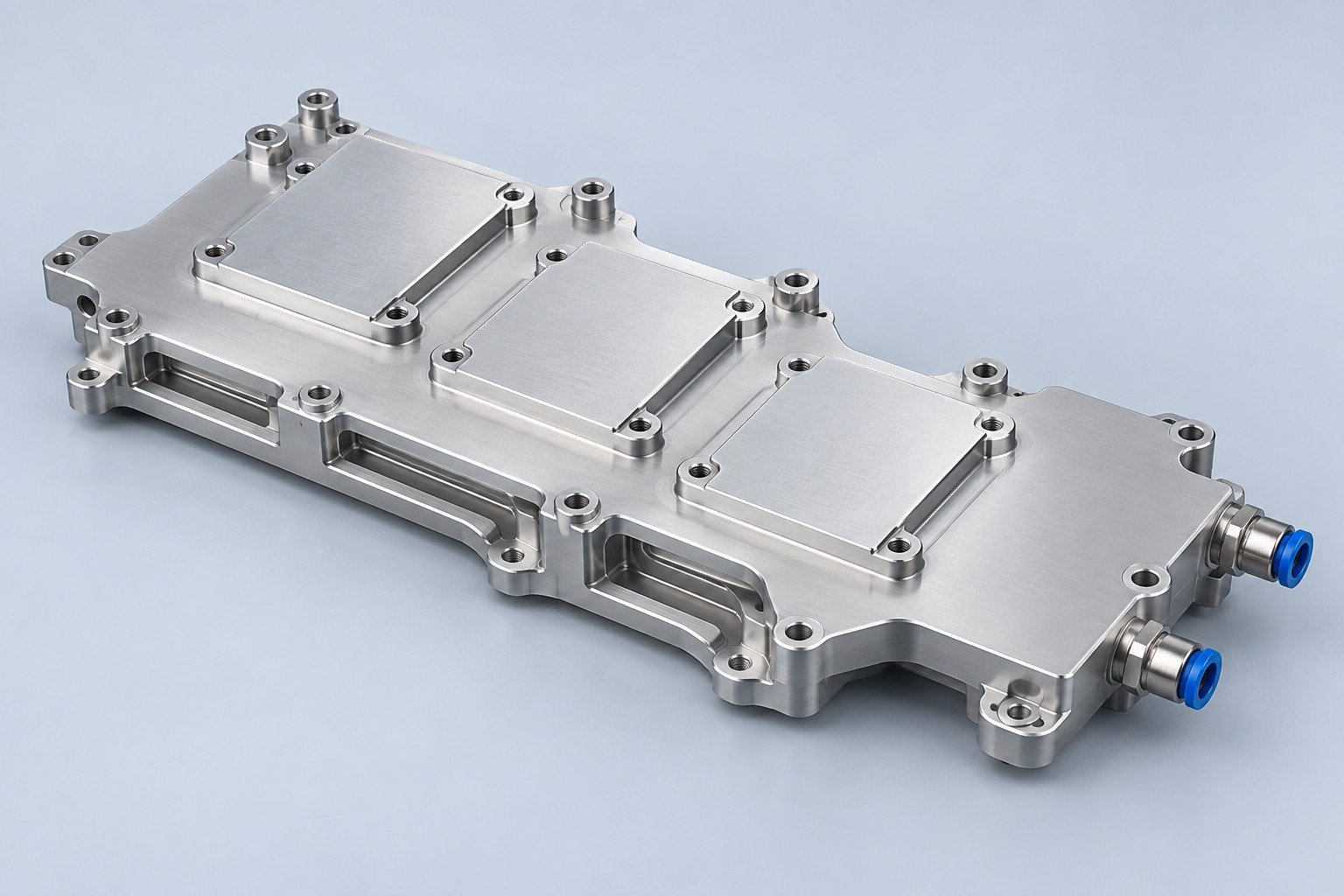
Components for your electronic systems.
Start with your functional and quality requirements.
Build around your operating environment.
From prototype to production, review material performance, manufacturability and cost for your part.
Review grade, temper and finish for your metal parts.
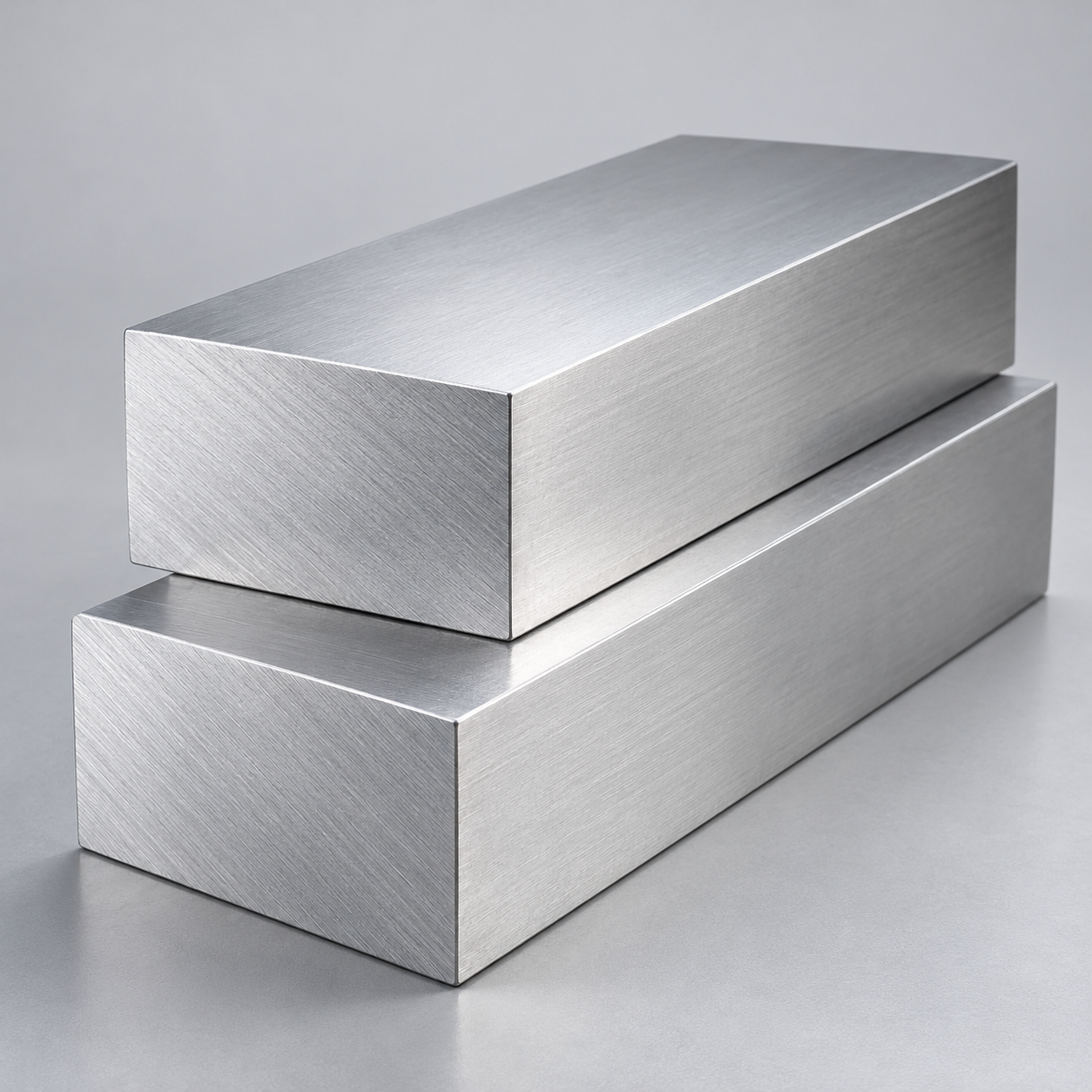 AluminumStrength, weight and machining›
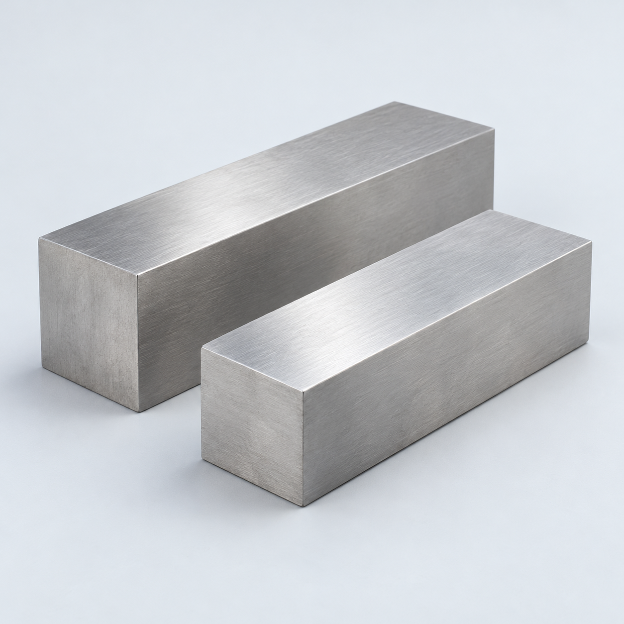 Stainless SteelCorrosion and finish requirements›
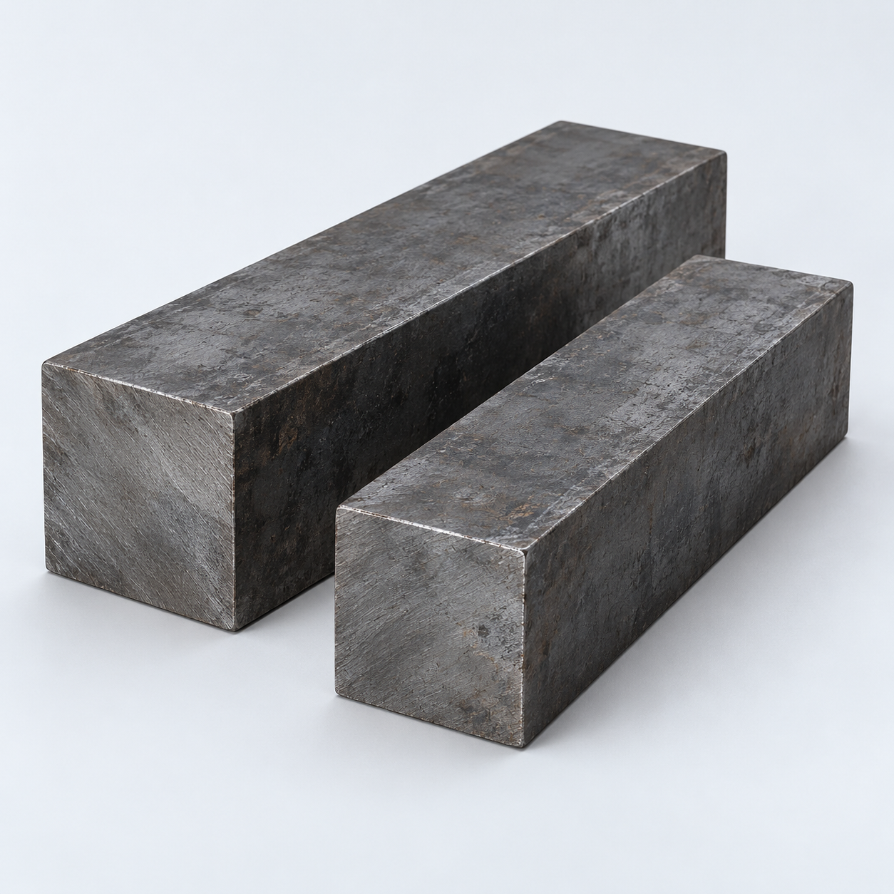 Carbon & Alloy SteelDiscuss grade and heat treatment›
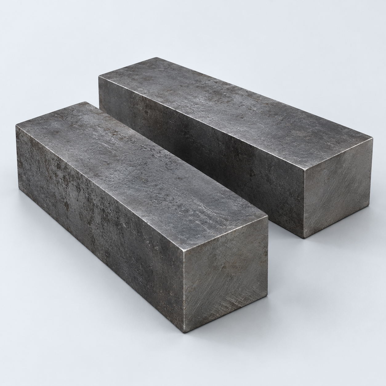 Tool SteelDiscuss tooling and wear needs›
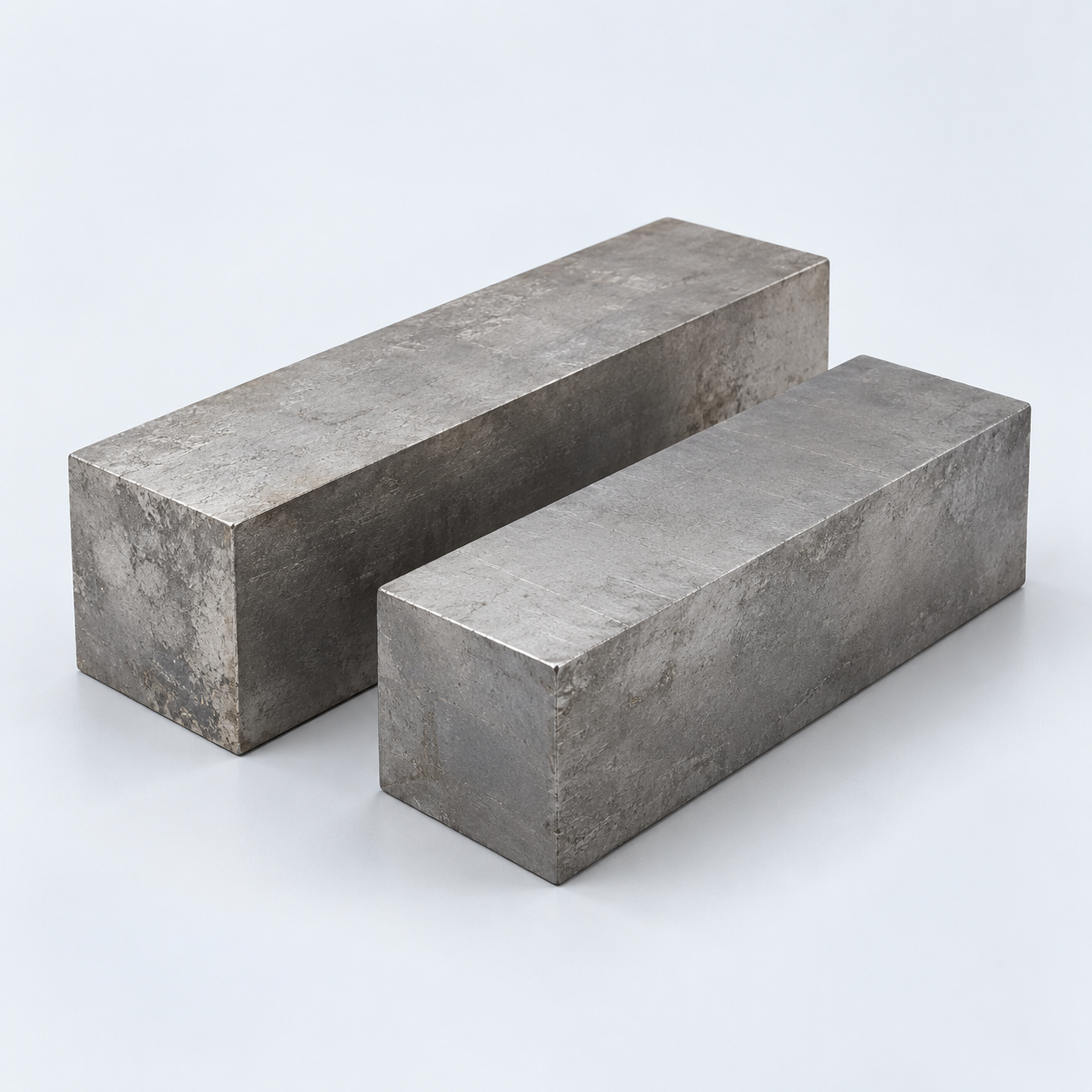 TitaniumReview grade and part geometry›
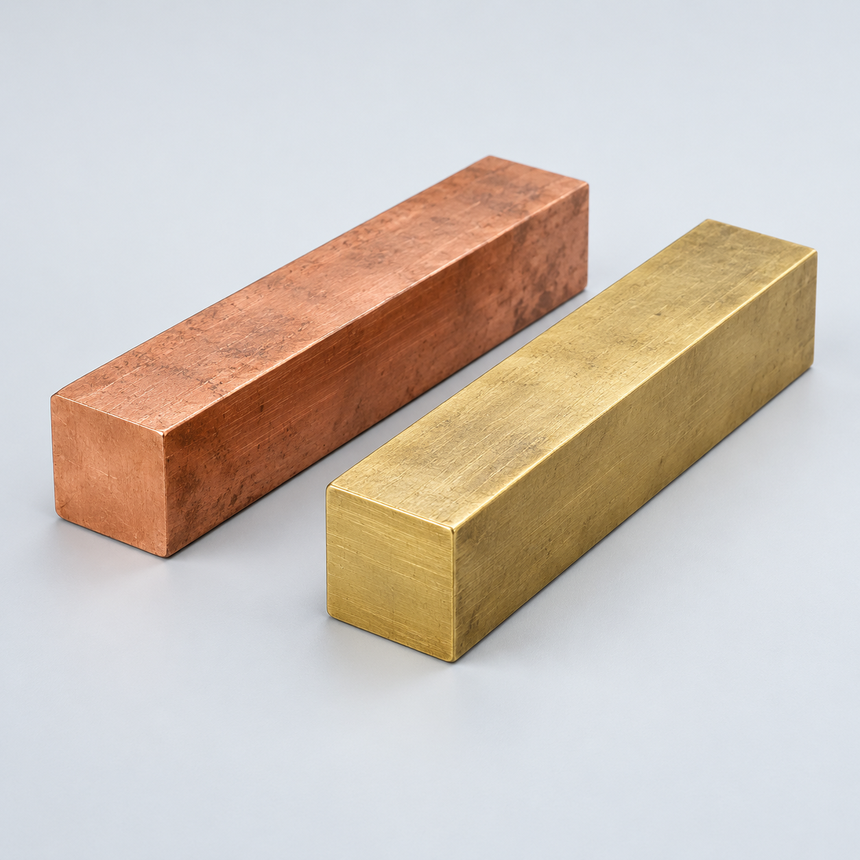 Copper & Brass & BronzeDiscuss conductivity and machining›
Match your polymer to function, process and environment.
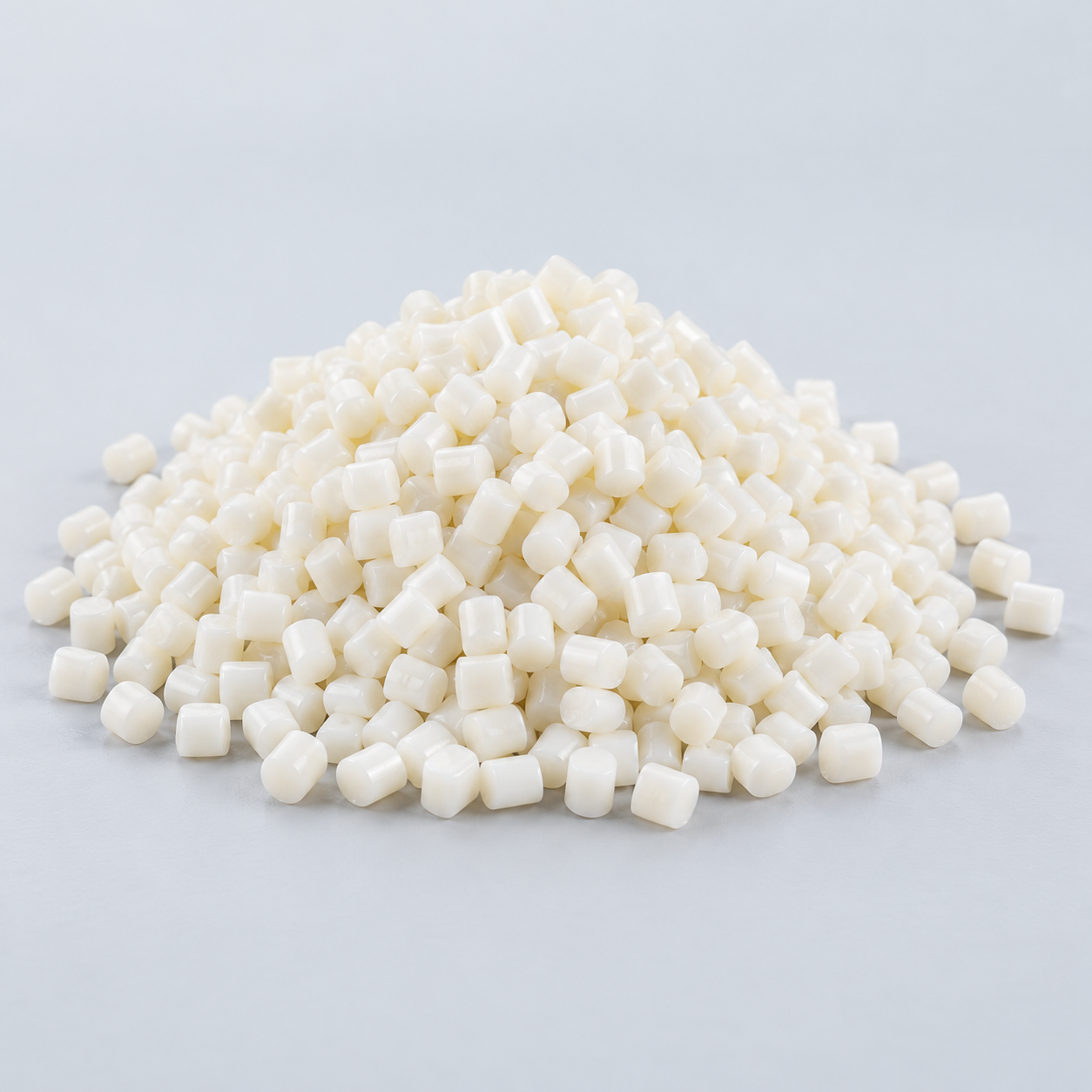 ABSReview enclosure and molding needs›
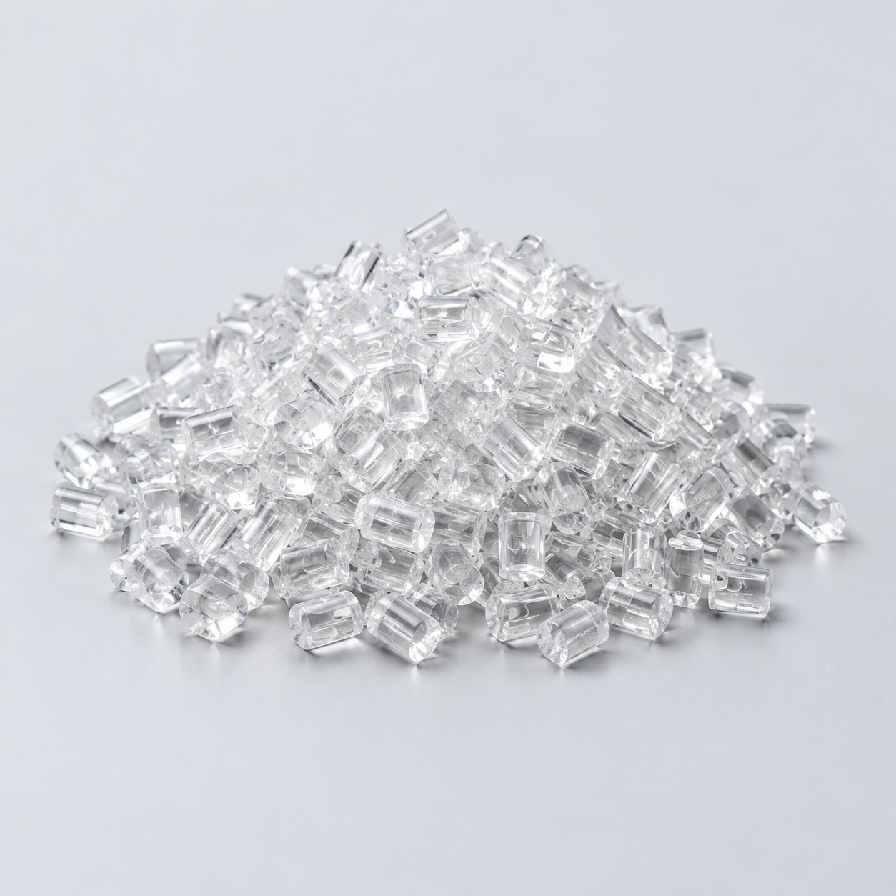 Polycarbonate (PC)Discuss clarity and impact needs›
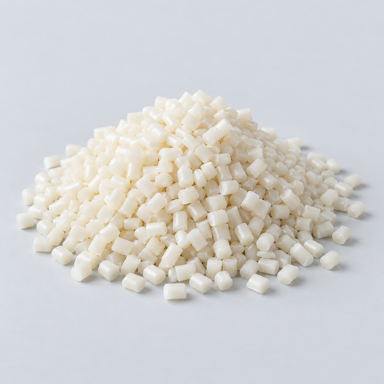 Nylon (PA)Review moisture and wear conditions›
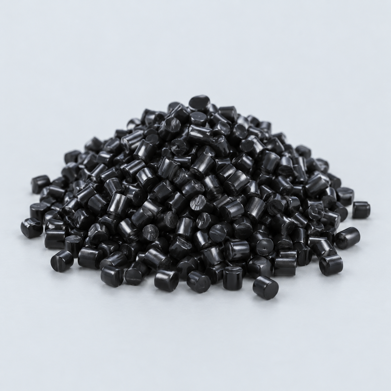 POM / AcetalReview fit and sliding features›
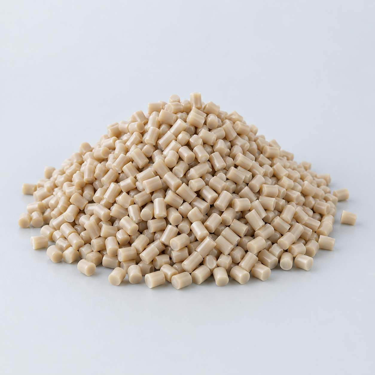 PEEKDiscuss operating conditions›
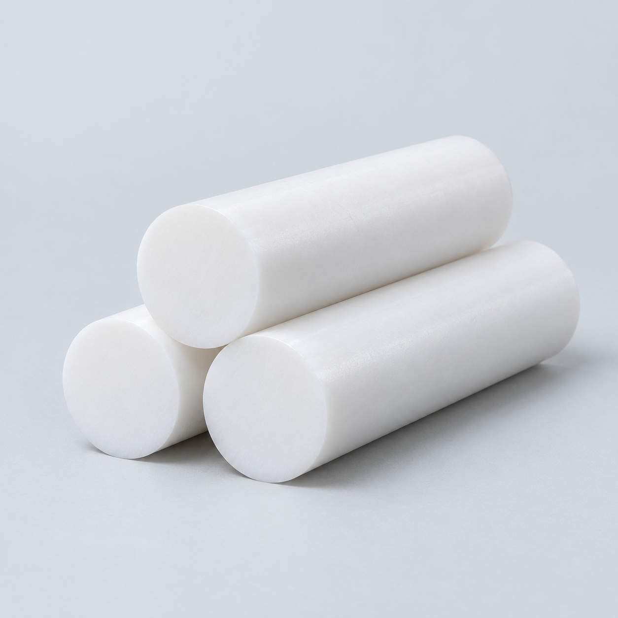 PTFEReview friction and chemical exposure›
 ULTEM / PEIDiscuss thermal and electrical needs›
Confirm grade availability and application requirements.
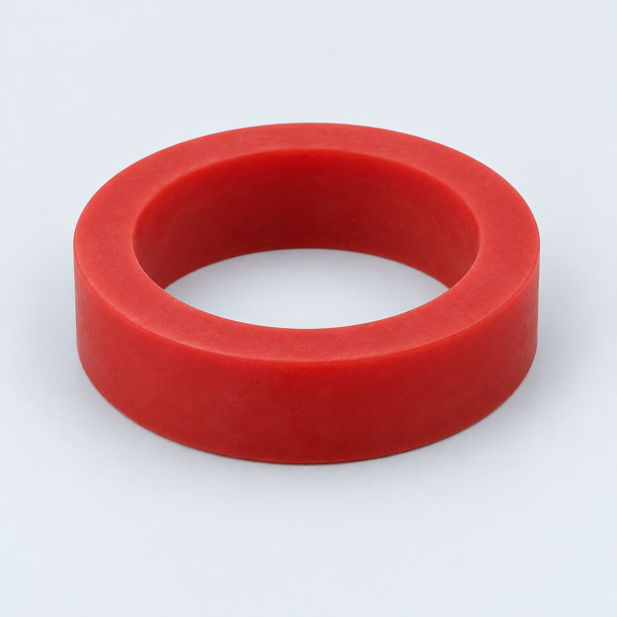 Silicone / LSRDiscuss flexible component needs›
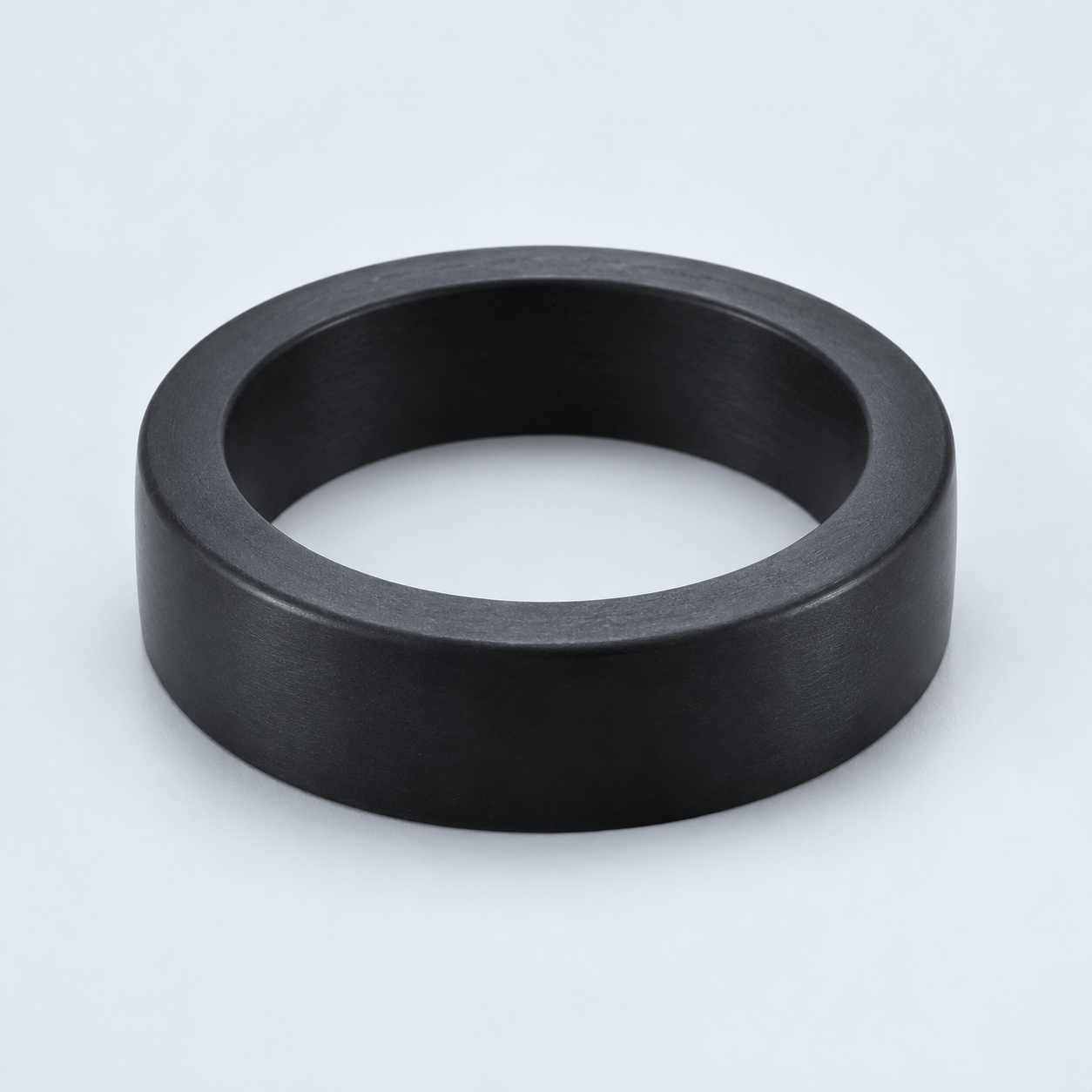 TPU / TPEReview flexibility and processing›
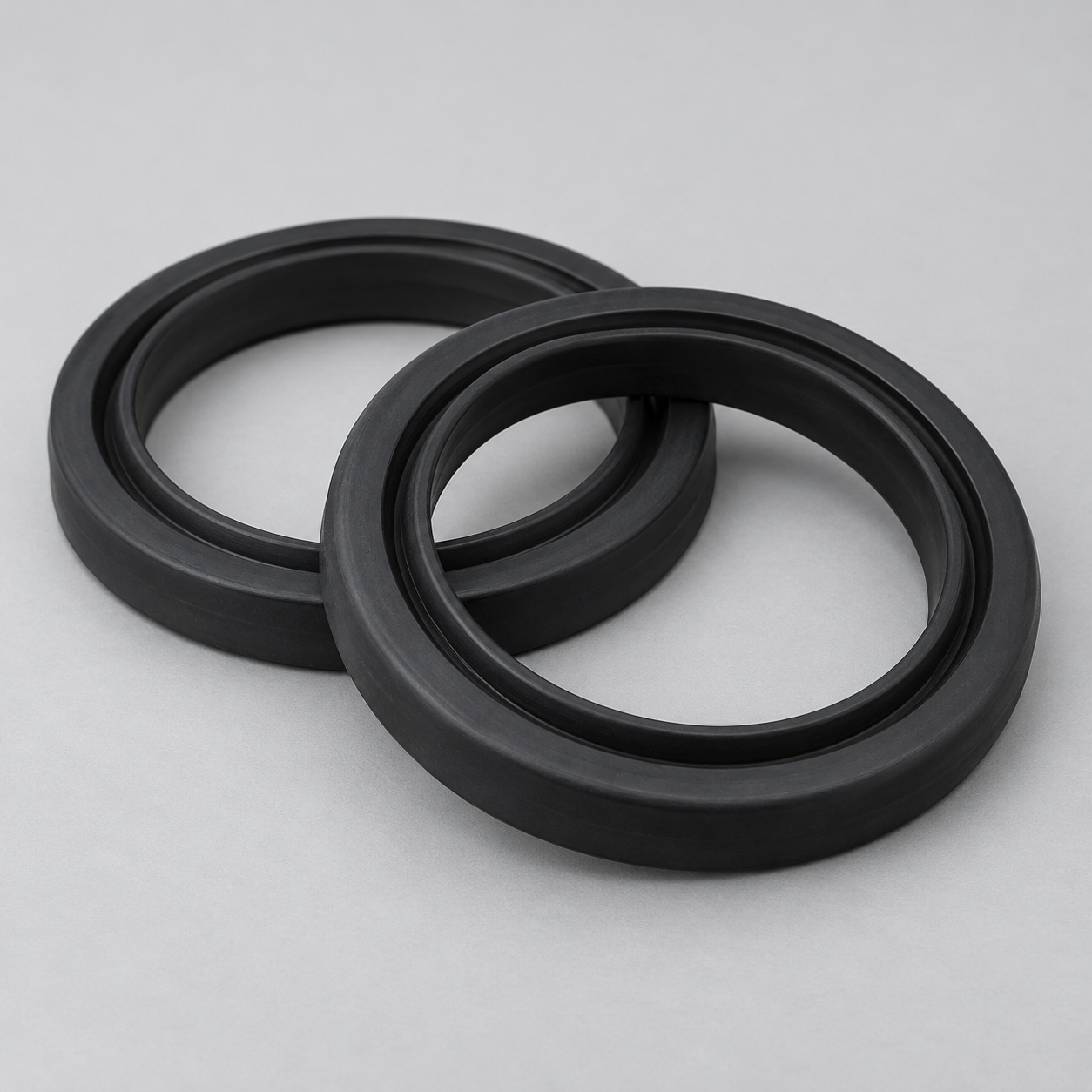 EPDMReview weathering and chemical exposure.›
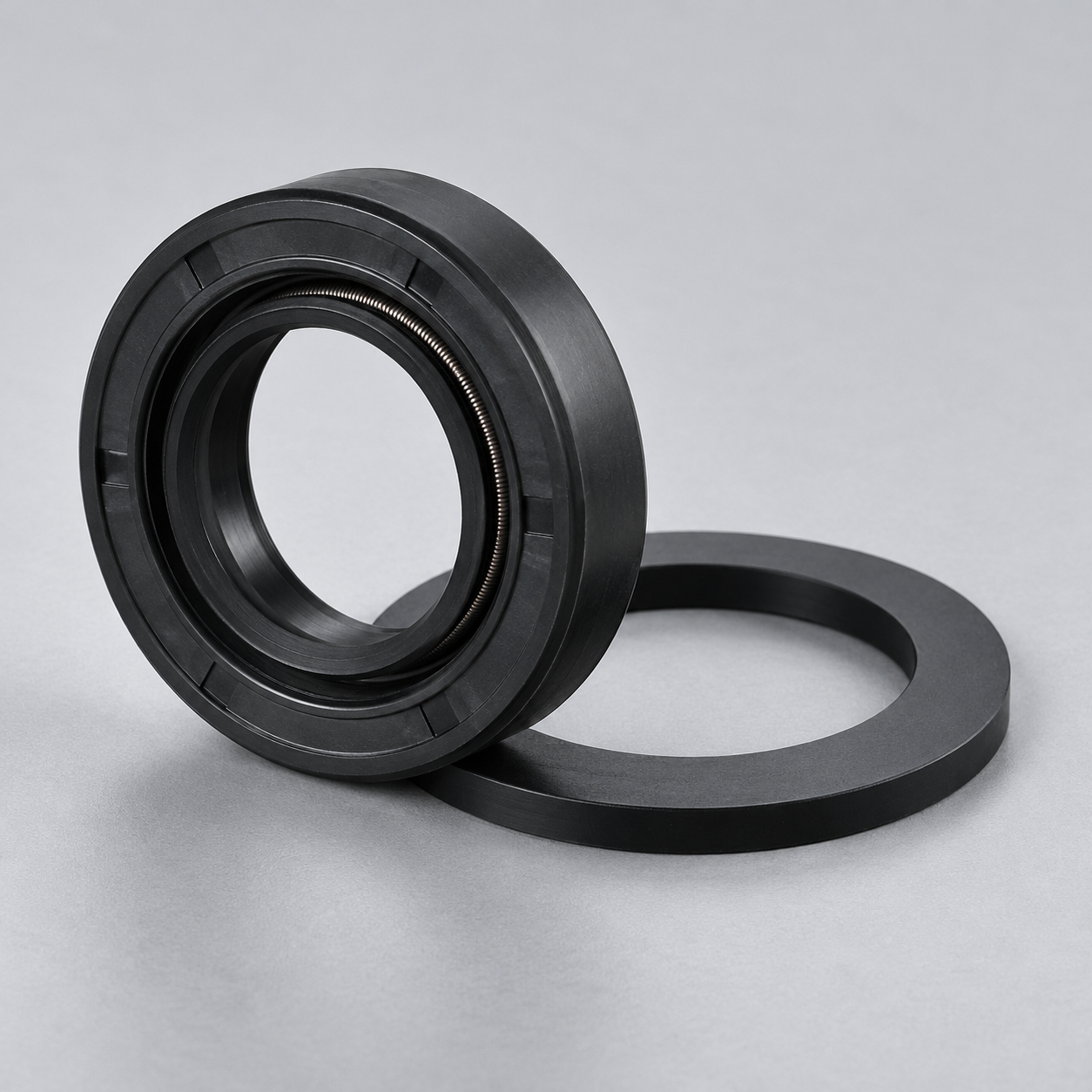 NBRReview oil and fuel exposure.›
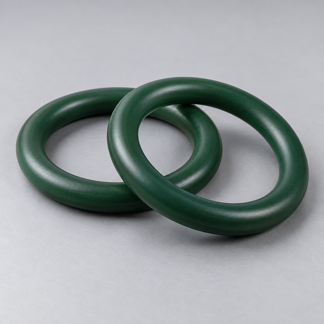 FKMReview temperature and chemical exposure.›
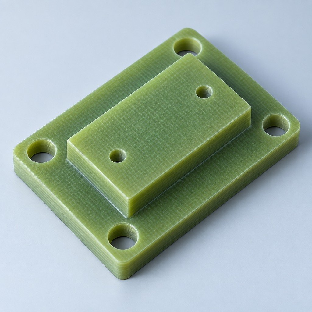 G10 / FR4Review insulation and laminate needs›
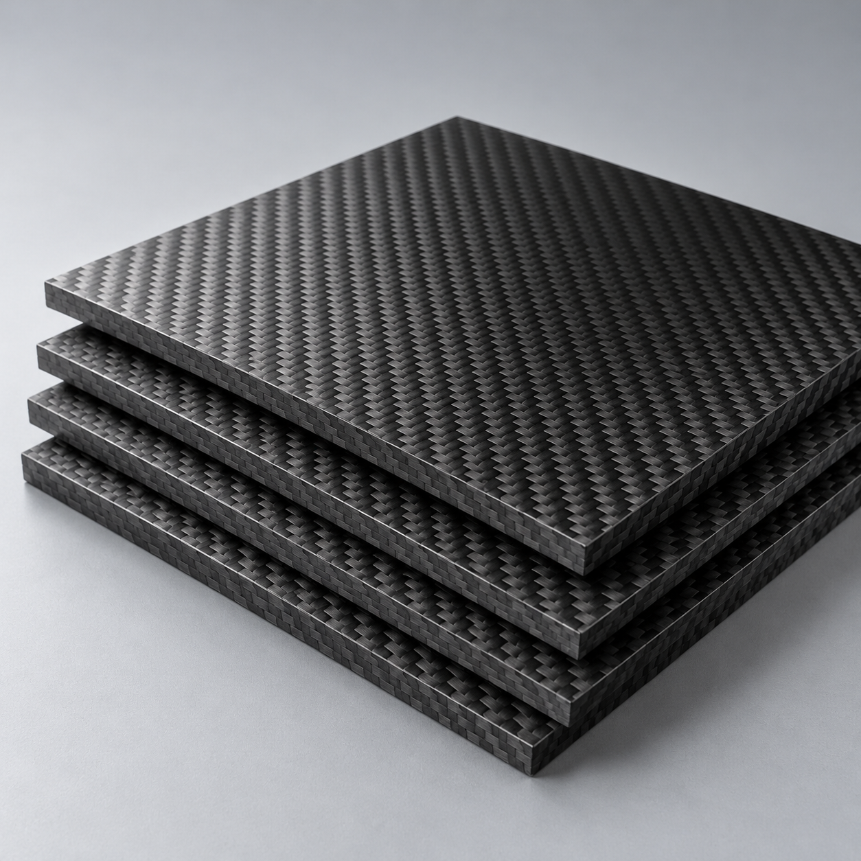 CompositesReview stiffness, weight and laminate.›Customer-Specified MaterialsConfirm your grade and requirements.›Other Specialty MaterialsDiscuss your application and grade.›
Practical guidance for your part geometry and material decisions.
Prepare your process, budget and sourcing questions.
Build your knowledge before production.
Learn who we are and how we operate.
Find our U.S. support team or start a conversation.
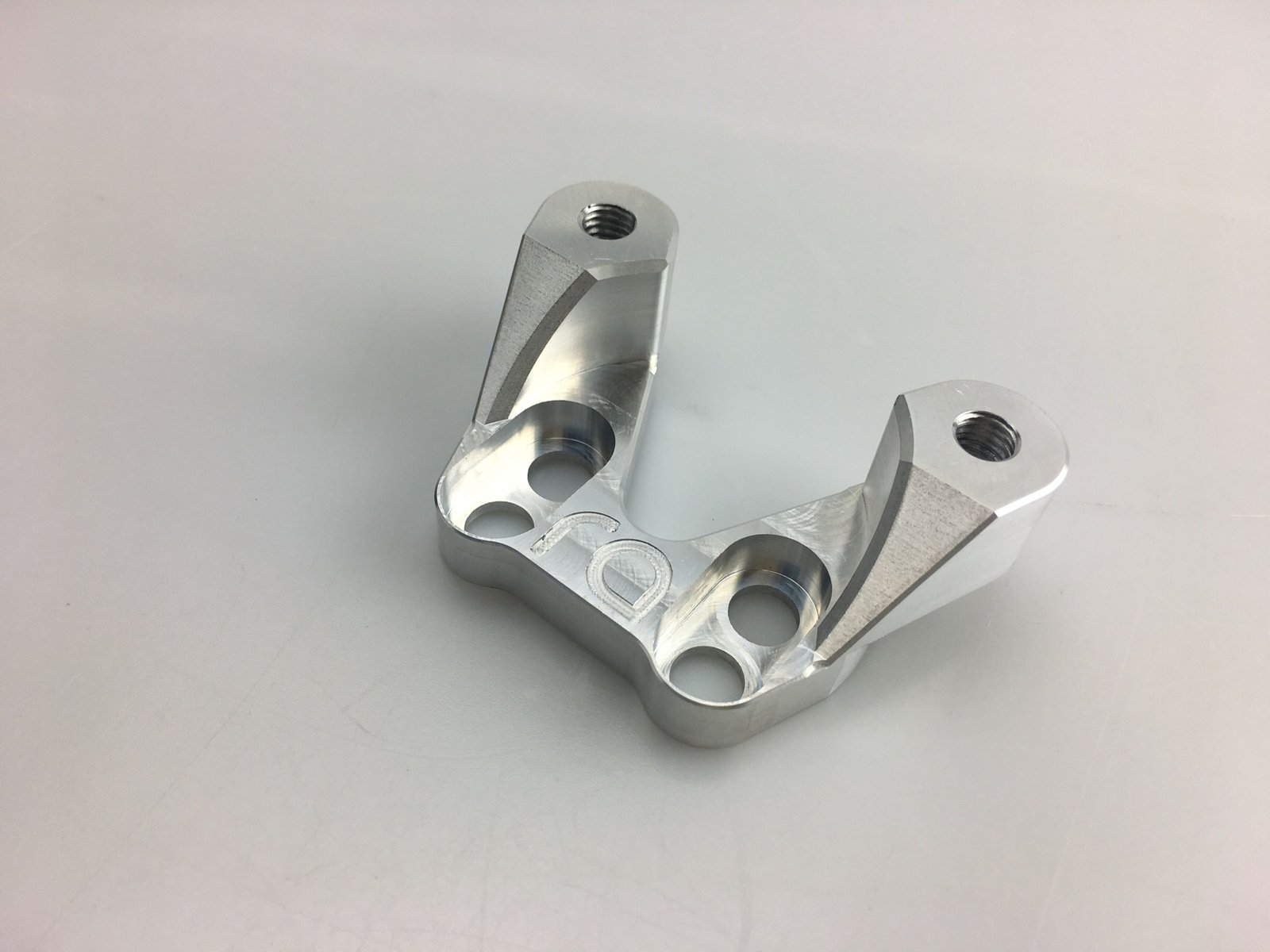
Send your CAD and controlled drawing for a feature-by-feature manufacturing review. Identify mounting datums, bushing fits, thread requirements and finish allowances before your prototype or repeat order is quoted. Your vehicle loads and installed-system validation remain part of your application specification.
Datums and bolt locations
Bushing and sleeve references
Loads and clearance envelope
Fits, finish and records
Made-to-drawing mechanical components · Define installed-system validation separately
Choose the interface you need manufactured; the drawing defines the actual part.
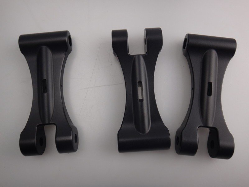
Define engine-side and chassis-side datums, pocket geometry and fastener access.
Explore billet brackets →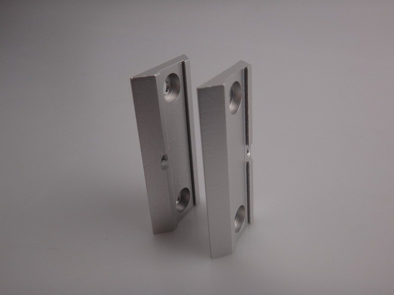
Specify bolt patterns, locating features, thickness and mating-face requirements.
Review CNC machining →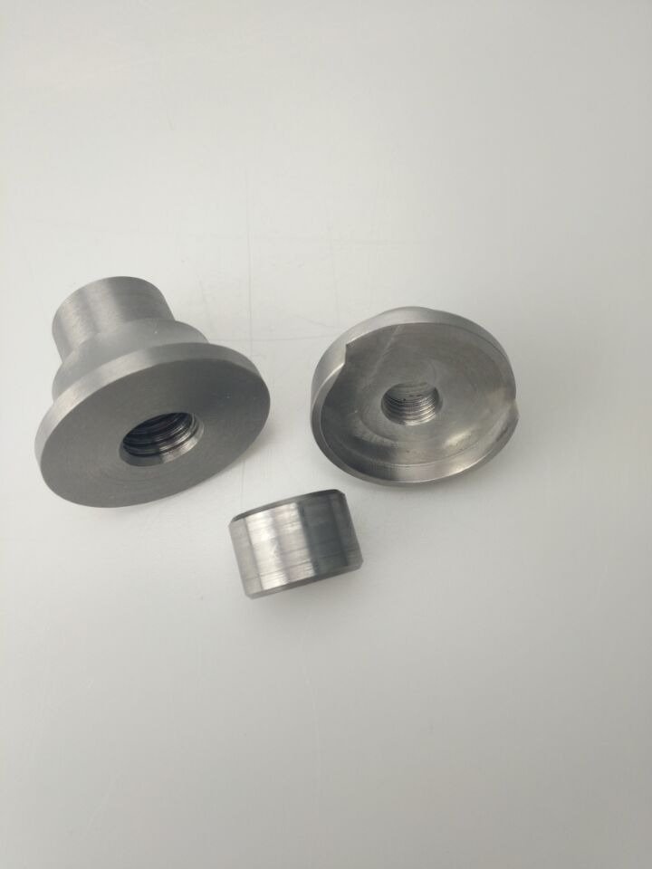
Review sleeves, bushings, spacers and the final bore or thread condition.
Explore precision spacers →Can your drawing be manufactured as specified? Request a documented response for each critical feature.
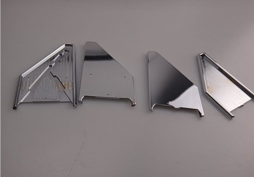
Reference hole locations to functional datums; identify positional or perpendicularity requirements on your drawing.
State the mating component, fit, surface condition and whether dimensions apply after finishing.
Specify thread standard, size, pitch, class, effective depth, inserts and any agreed gauge requirements.
Supply the mating CAD envelope and wrench access. Identify assembly order and protected interfaces.
Compare your released drawing with proposed changes before production. Ask which feature adds an operation, special tooling or inspection time.
Review a tool-accessible internal radius. Keep a sharp corner only where its function requires a separate operation.
Compare tool reach, wall support and machining sequence before approving the geometry.
Separate functional fits from general dimensions; review proposed relaxations against the mating assembly.
8 process reviews connect geometry, material condition, quantity and inspection scope.
Review tool access, internal radii, locating datums and multi-face setup. Confirm the required axes and inspection method after drawing review.
Review process requirements →Review concentric sleeves, shoulders and threaded components. Swiss suitability depends on diameter, geometry and quantity.
Review process requirements →Review formed accessory brackets, bend references, flat-pattern allowances and coating masks.
Review process requirements →Compare tooling, draft and repeat demand; define which bores and faces need subsequent machining.
Review process requirements →Review profile feasibility, stock condition, cut length and subsequent machined interfaces.
Review process requirements →Use an agreed prototype objective such as packaging or clearance review. A fit model does not establish load capacity.
Review process requirements →Review non-load-bearing covers or ancillary plastic components separately from the structural engine mount.
Review process requirements →Identify inaccessible features or final surface requirements; confirm availability and outside-process scope in your quotation.
Review process requirements →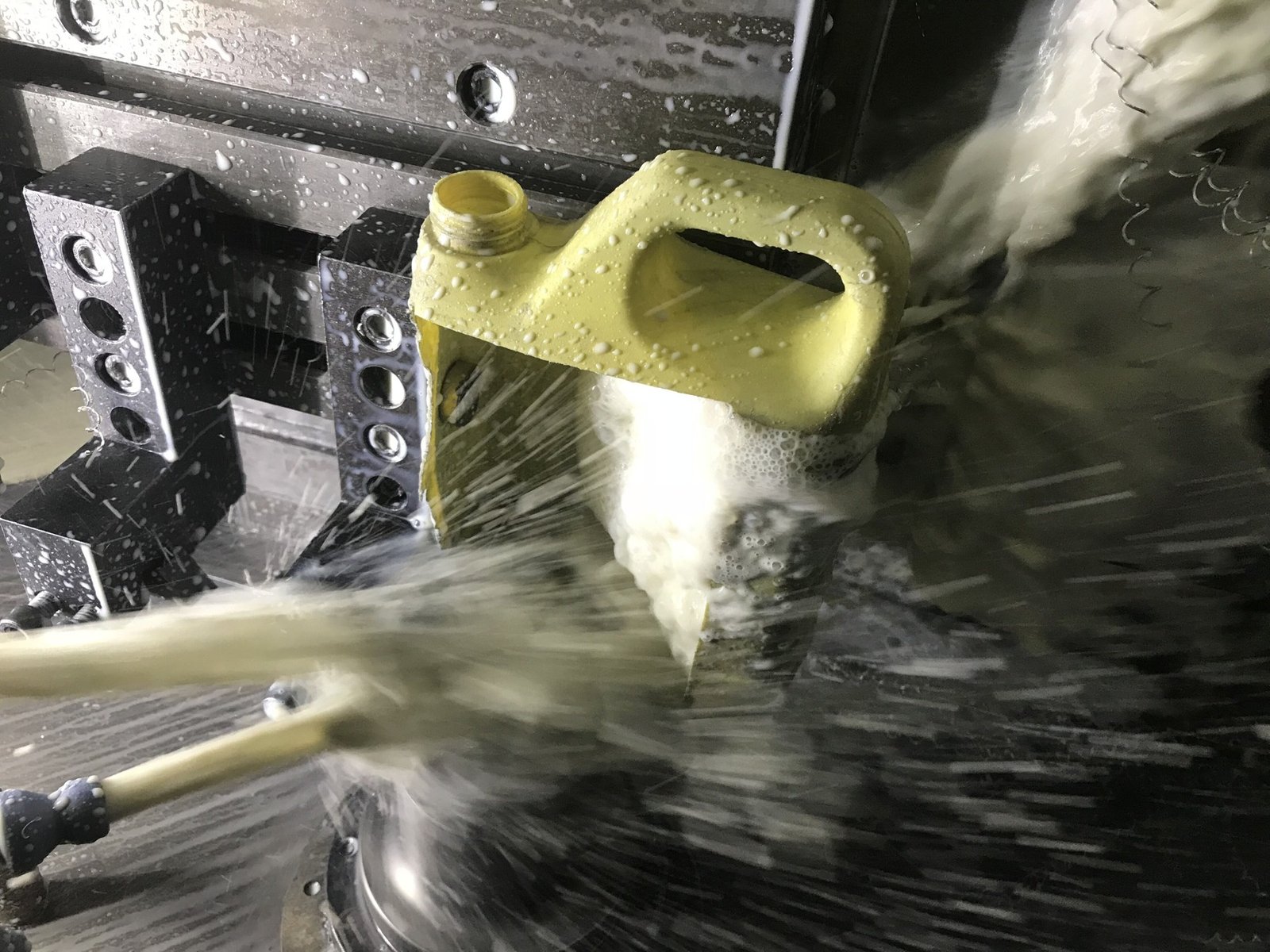
CAD plus revision, units, datums and dimensional requirements.
Bushing, fastener and chassis references plus assembly clearance.
Exact grade, temper, stock form and certificate requirement.
Coating, approved color reference, masks and final fits.
Prototype quantity, repeat demand and proposed shipment releases.
Critical dimensions, sampling, report format and approval owner.
Control the final condition your assembly and your customer will receive.
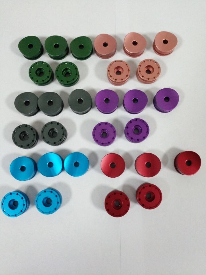
Agree alloy, pre-treatment, coating specification and approved color sample. Confirm dimensions after coating and identify masked bores or threads.
Define wear faces, final dimensions and masked fits. Confirm coating class, thickness and inspection in the quotation; do not assume the same appearance as decorative anodizing.
Use an approved physical sample, specified viewing conditions and agreed color-difference acceptance. Record alloy, pre-treatment, finish and batch references for repeat orders. Different alloys and batches may look different.
Mark threads, grounding/contact faces and bushing seats that require masking or post-finish work. Confirm gauges and whether thread fit is accepted before or after coating.
State coating-thickness locations, appearance zones, sampling and required records. Any standard or test applies only when confirmed for your material and finish.
Identify cosmetic faces, threads and precision bores; agree separators, bags or individual protection.
Confirm quantity per bag/carton, part ID, revision, gross weight and carton dimensions.
Agree pallet requirements, labels and shipment release quantities before production.
| Your packing input | Confirm in your quote |
|---|---|
| Carton quantity / dimensions | Per part and shipment |
| Gross weight / pallet size | After packing review |
| Part number / revision labels | Approved artwork and format |
Agree the evidence needed to approve your part; a sample photograph is not an inspection record.
For your engine mount program, distinguish where the part is made from where your project communication is supported.

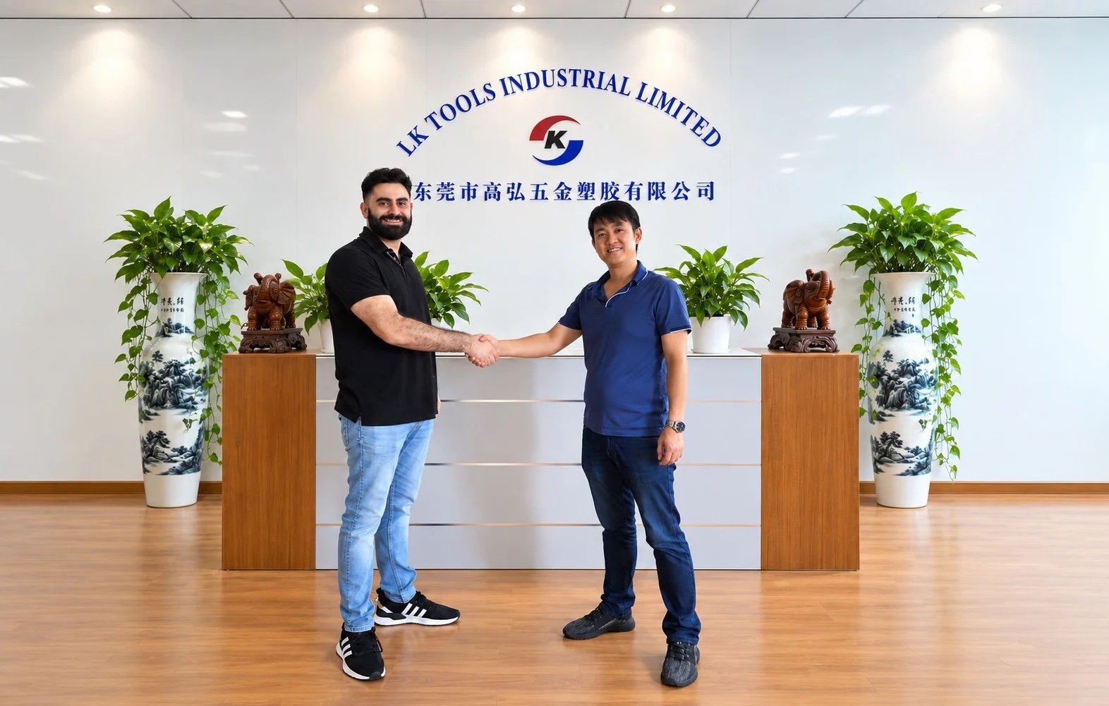
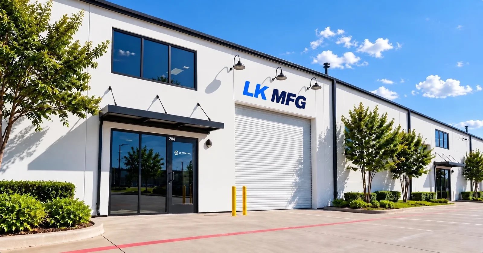
Agree who owns the drawing and sample approval.
Confirm packing, delivery terms and import responsibilities.
Discuss local coordination and any inventory arrangement.
Genuine company and customer-discussion photographs. Manufacturing in China; U.S. support does not mean U.S. manufacture or a default local stock program.
Factory & Operations →Request a feature-by-feature feasibility response. Record exceptions before an order is accepted.
Identify datums, critical dimensions, sampling and the required report format.
Agree material certificates, finish evidence and any subcontracted process scope.
Review fit and dimensional evidence; confirm any customer-specific FAI or PPAP scope in the quotation.
Use agreed milestones rather than an unverified fixed lead-time promise.
Resolve missing dimensions, conflicting notes and acceptance requirements.
Approve proposed changes and compare setup, tooling, material and inspection scope.
Check dimensional results, assembly fit and appearance against agreed criteria.
Freeze the approved revision and record quantity, finish and packing instructions.
Confirm records, shipment quantity and delivery arrangements before dispatch.
Compare what is included before you compare unit prices.
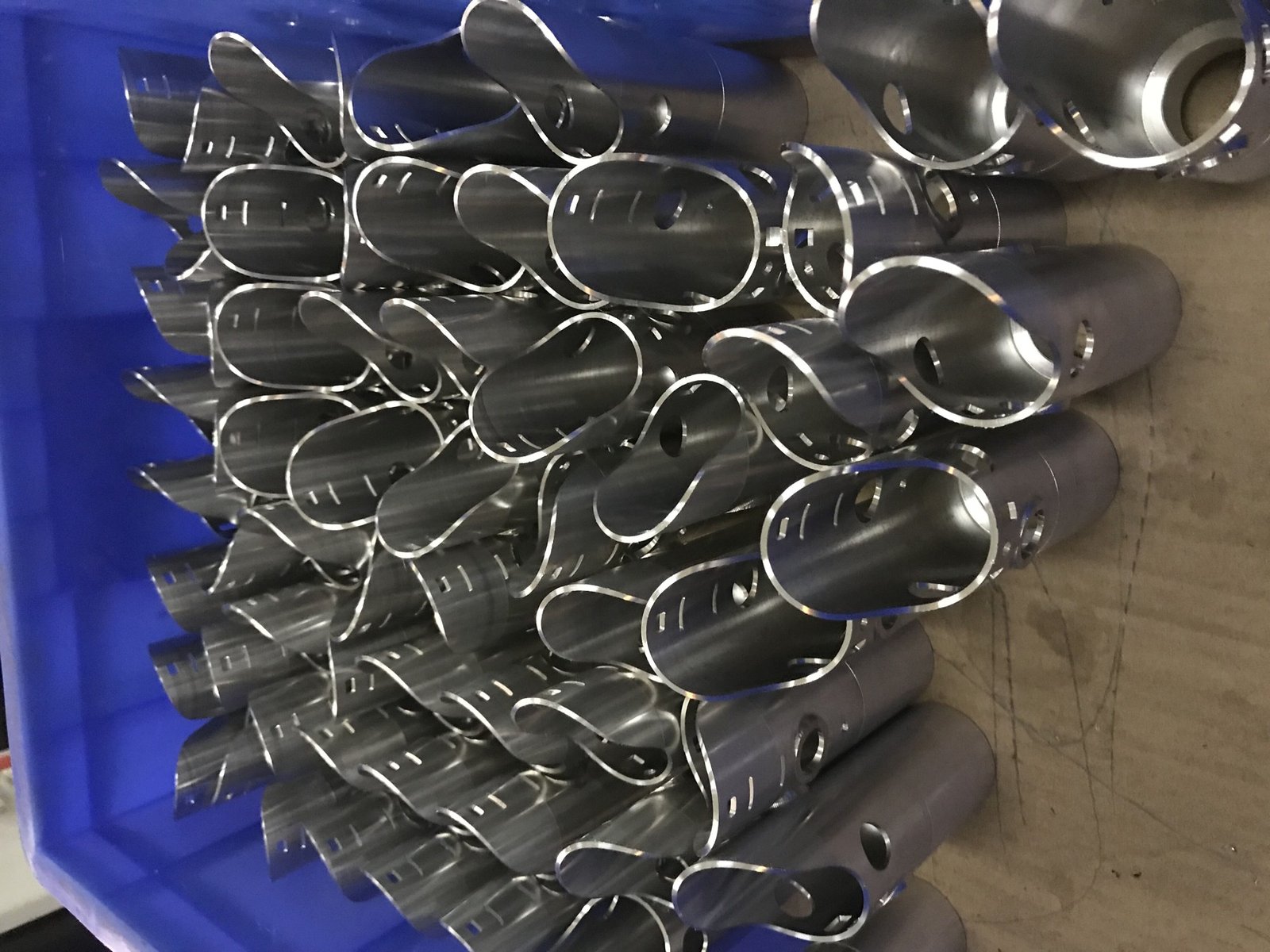
Genuine supplied component batch photograph. Agree release quantity, part identification and packing for your order.
Compare the same scope: unit price, setup/tooling, inspection, packing, freight, duty/tax, clearance and final delivery. Incoterm, named place and exclusions belong in your quote.
Confirm the proposed HS/HTS classification with the broker or responsible customs party using part function, material and destination. Request the declared description, origin, value, duty/tax basis, brokerage, freight and last-mile charges. DDP availability, importer responsibilities and exclusions require written confirmation; no fixed code or rate is promised for every engine mount.
Specify mating fasteners, engagement, inserts, torque instructions if supplied, locking method and any assembly verification. Confirm whether coating changes thread fit and which party supplies hardware.
Compare a one-time order with an agreed blanket quantity and scheduled releases. Define minimum production/release quantities, forecast window, ownership, storage fees and obsolete-stock responsibility; local inventory is not assumed.
Confirm payment milestones, approved sample status and the process for reporting a discrepancy. Agree affected quantities, evidence and disposition before rework, replacement or credit is authorized.
Upload the drawing revision, material, finish and quantities. Include mounting datums, bushing references, load inputs, final bores, material condition and required records.
Resolve mounting geometry, isolator responsibilities and acceptance before release.
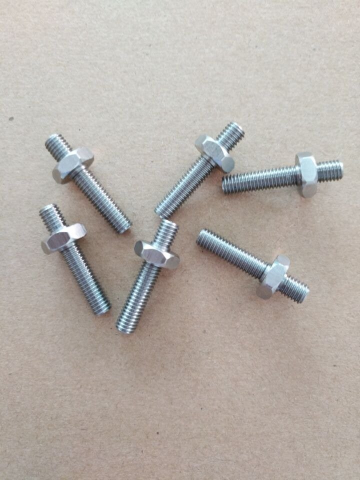
Send CAD, the released drawing, engine and chassis references, bushing specification, critical fits, material condition, quantities and inspection requirements.
Provide the approved isolator and sleeve requirements for your design. Vibration targets and installed-system validation need a defined engineering scope.
A photograph supports the brief but cannot establish hidden dimensions, load requirements or datum relationships. Supply controlled geometry and retained references.
No. Appearance cannot establish fatigue life or load capacity. Provide the design requirements and validation plan for your application.
Define the final fit, coating thickness requirements and masking instructions on the drawing. Agree inspection in the finished condition.
Discuss prototype and repeat quantities together. Preserve the approved revision, material, finish, fit and records for subsequent orders.