Injection Molding
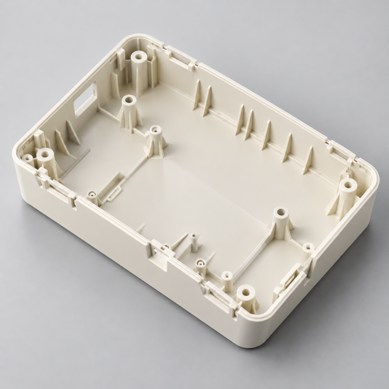
Tooling and molding for your repeat plastic parts.
From prototype to production, coordinated manufacturing solutions for your custom parts.
View All Services →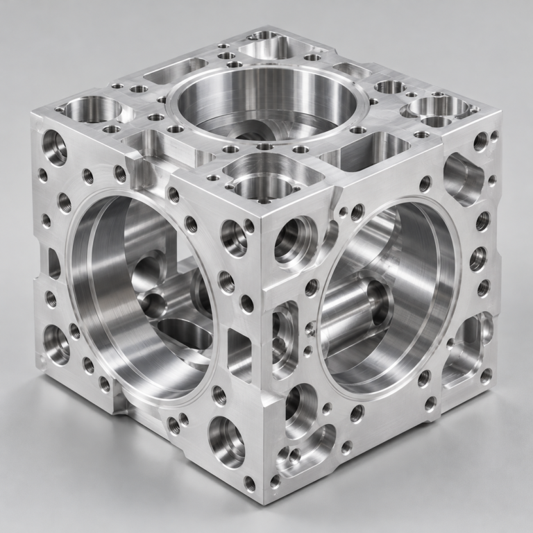
Precision parts for your tight tolerances and complex geometry.
Tooling and molding for your repeat plastic parts.
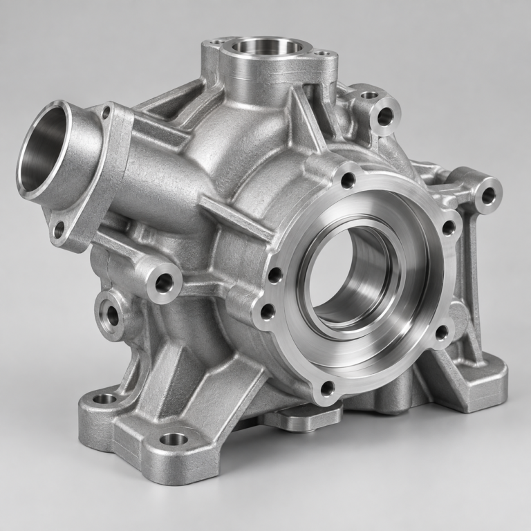
Metal casting options for your part and production volume.
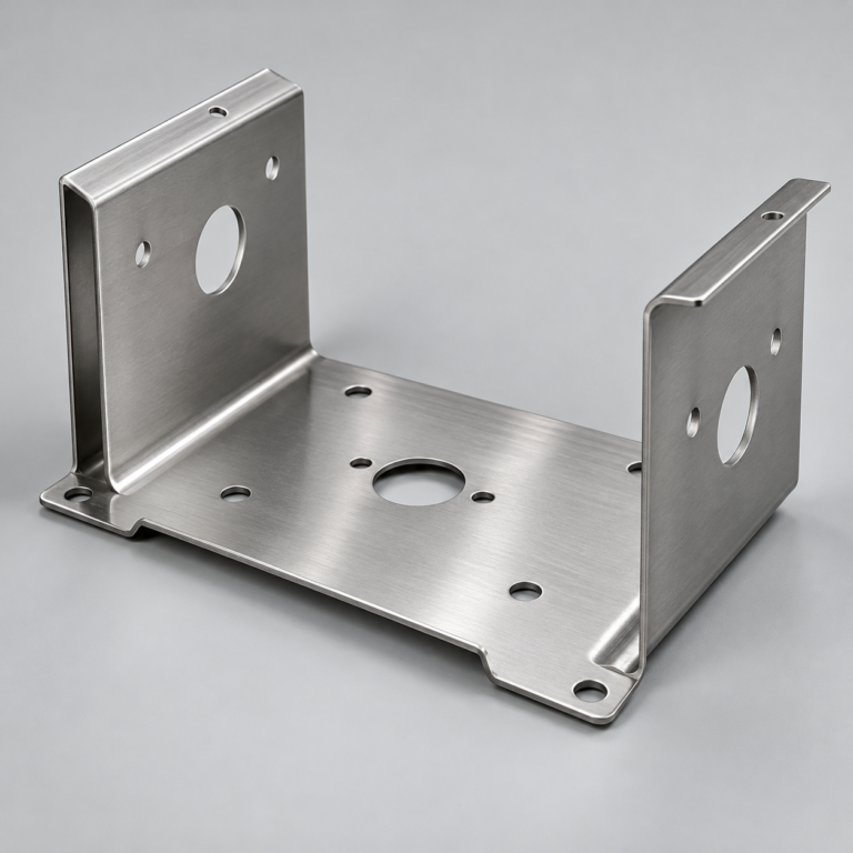
Cutting, forming and welding for your fabricated parts.
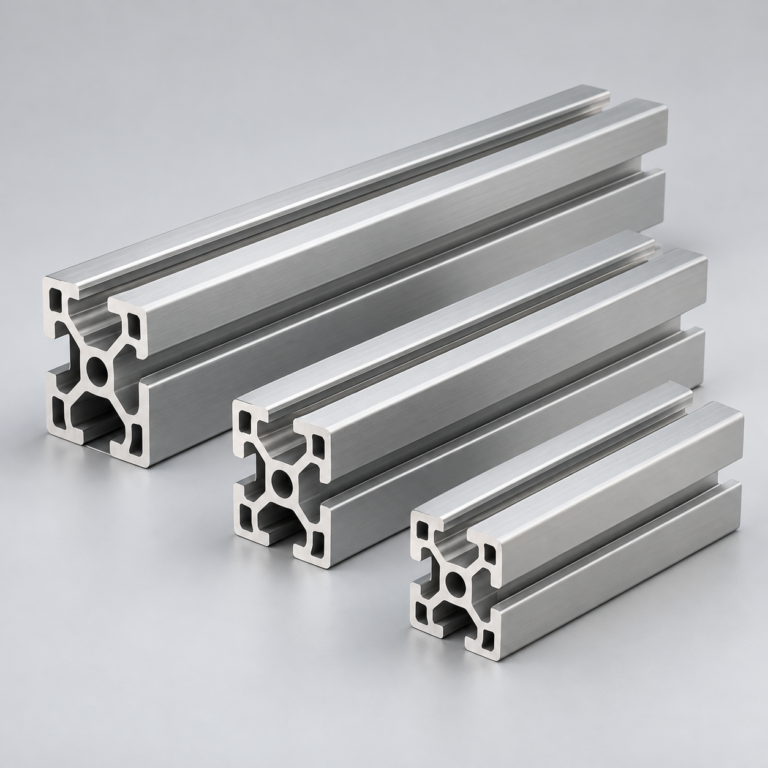
Custom profiles for your section, length and finish requirements.
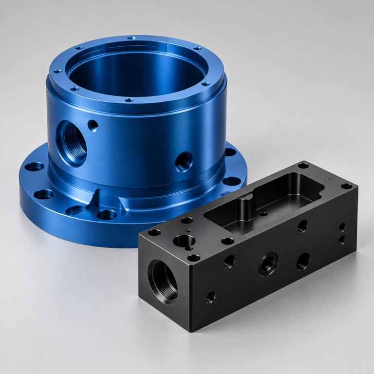
Finishes for your appearance, corrosion and wear requirements.
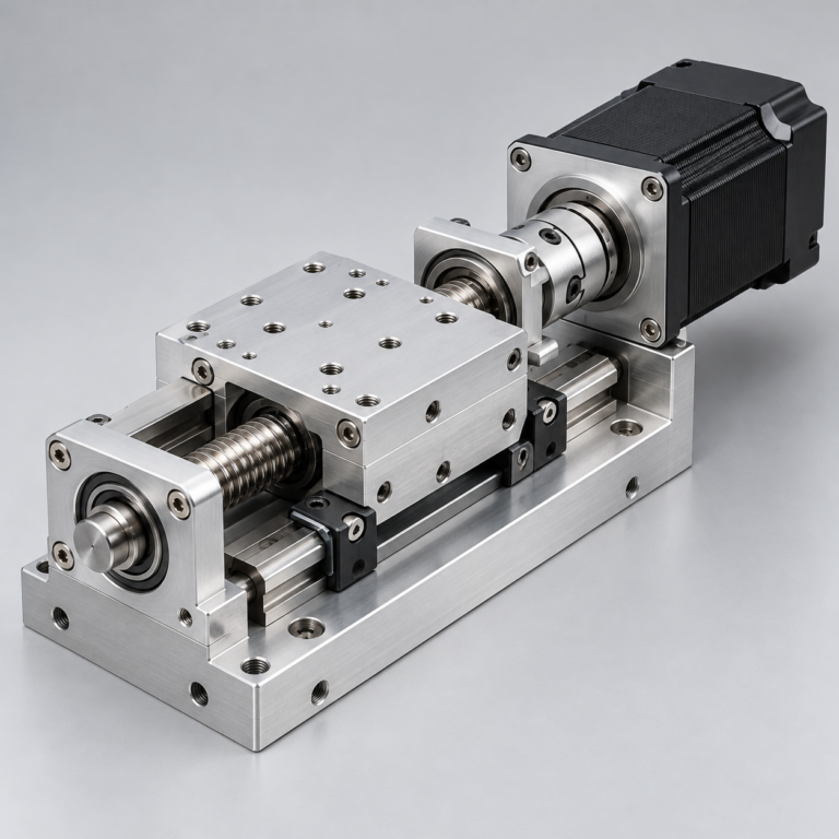
Sub-assemblies and final builds for your production program.
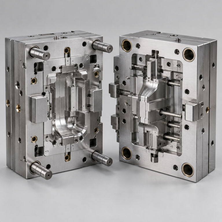
Production tooling built around your process and volume.
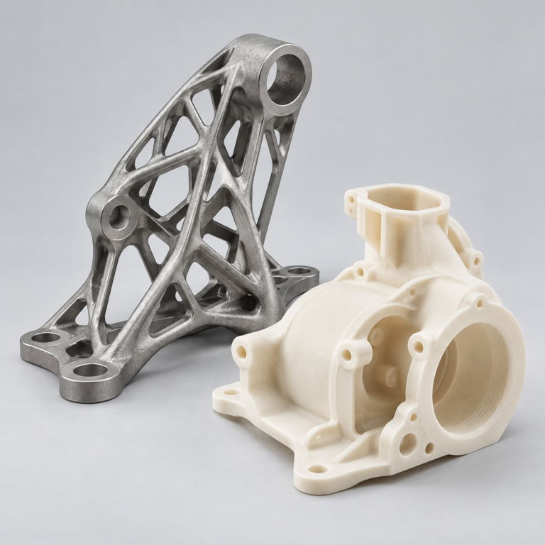
Prototype parts to check fit, function and design.
DFM, process planning and production support for your project.
Inspection, documentation, inventory and delivery planning for your program.
Choose air- or liquid-cooling components around your thermal and mechanical requirements.
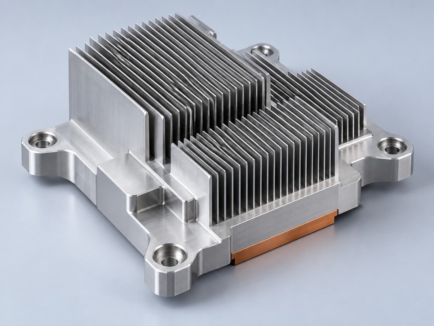
Manufacturing support for your cold plates, manifolds and cooling assemblies.
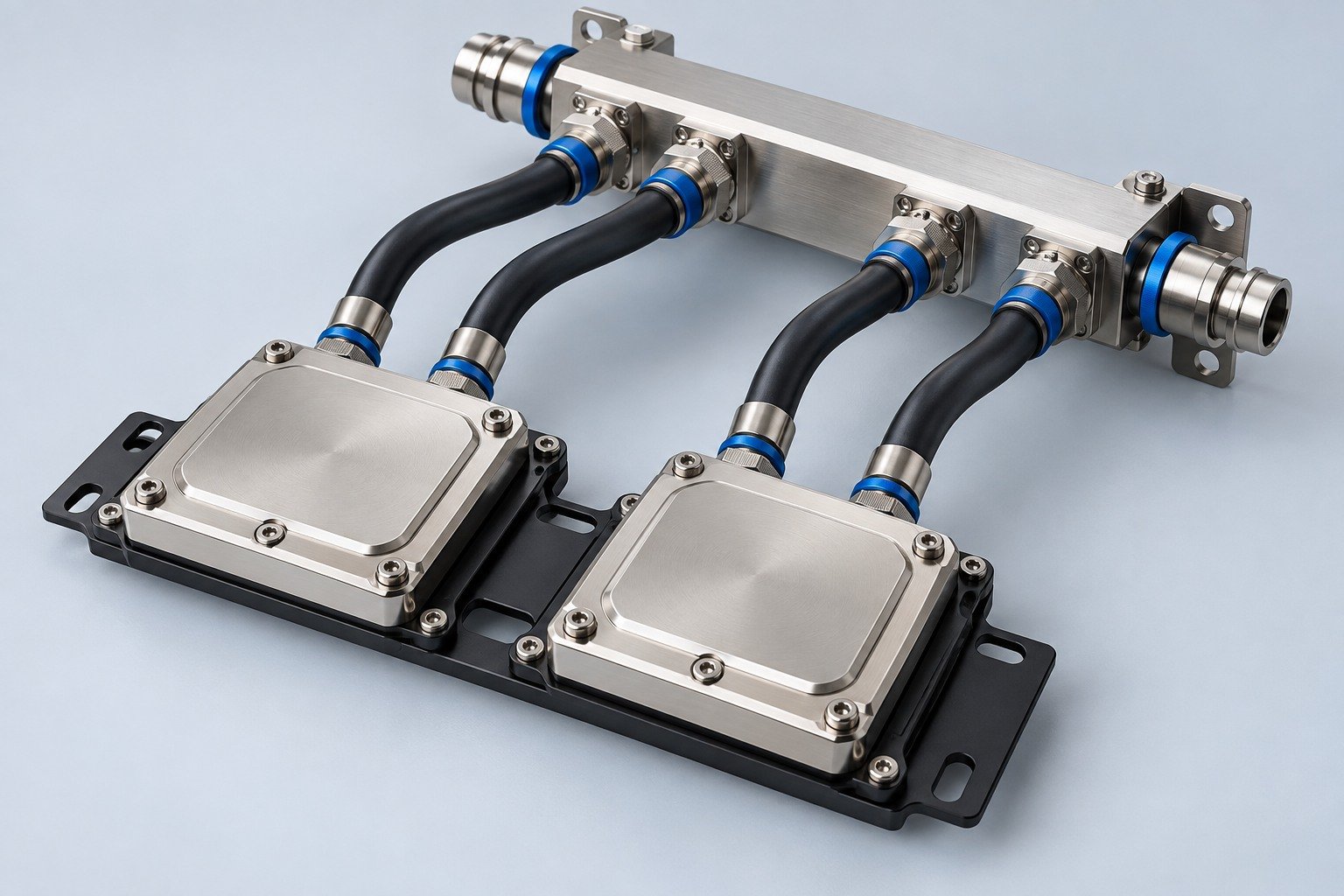
Find components for your power electronics, energy, laser and telecom application.
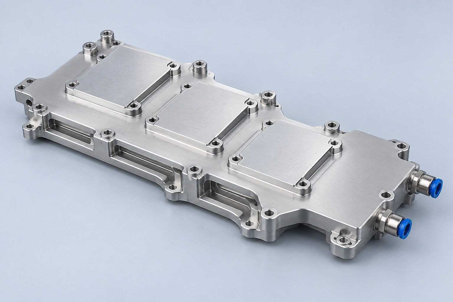
Components for your electronic systems.
Start with your functional and quality requirements.
Build around your operating environment.
From prototype to production, review material performance, manufacturability and cost for your part.
Review grade, temper and finish for your metal parts.
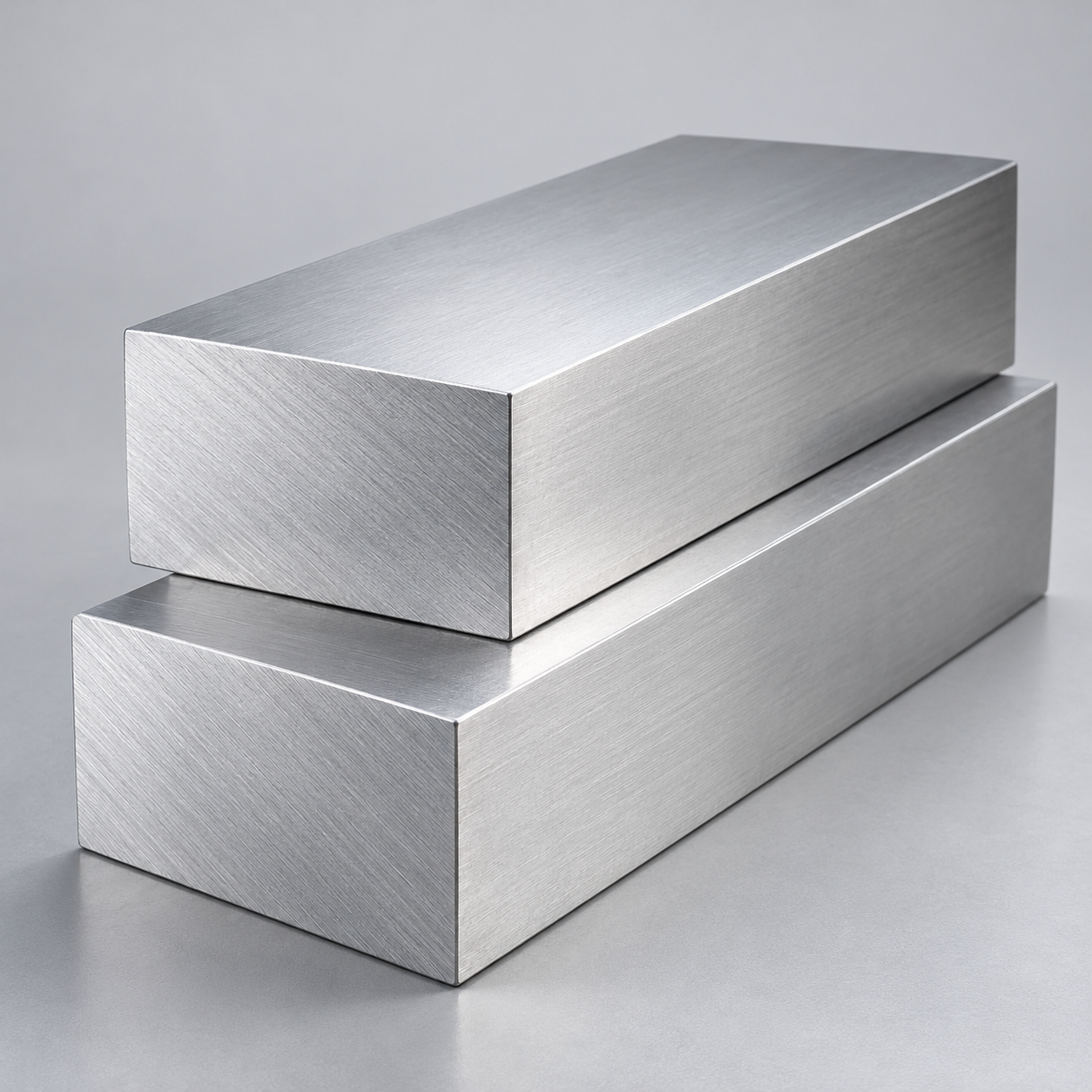 AluminumStrength, weight and machining›
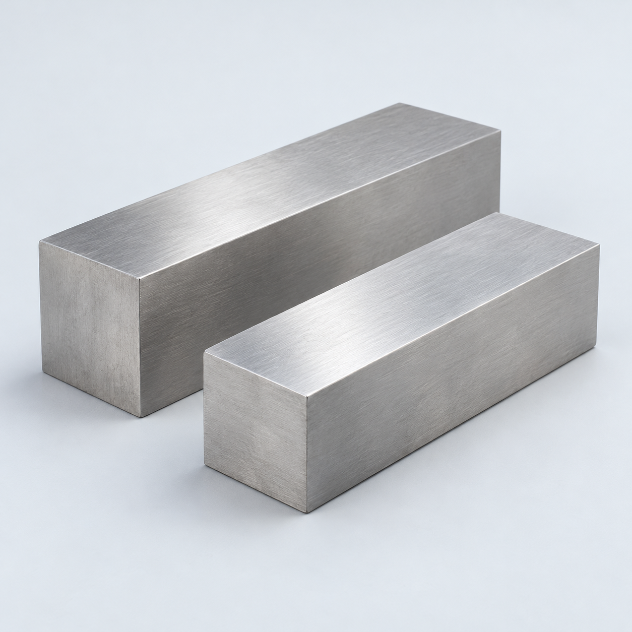 Stainless SteelCorrosion and finish requirements›
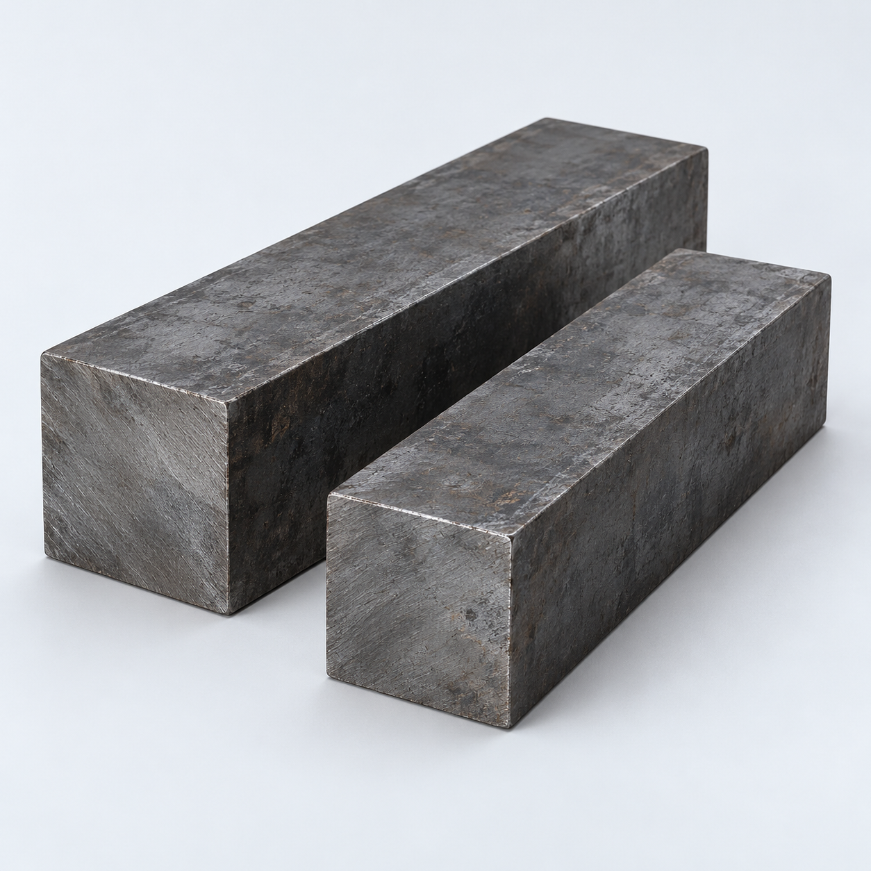 Carbon & Alloy SteelDiscuss grade and heat treatment›
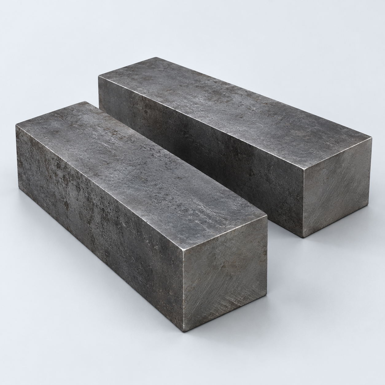 Tool SteelDiscuss tooling and wear needs›
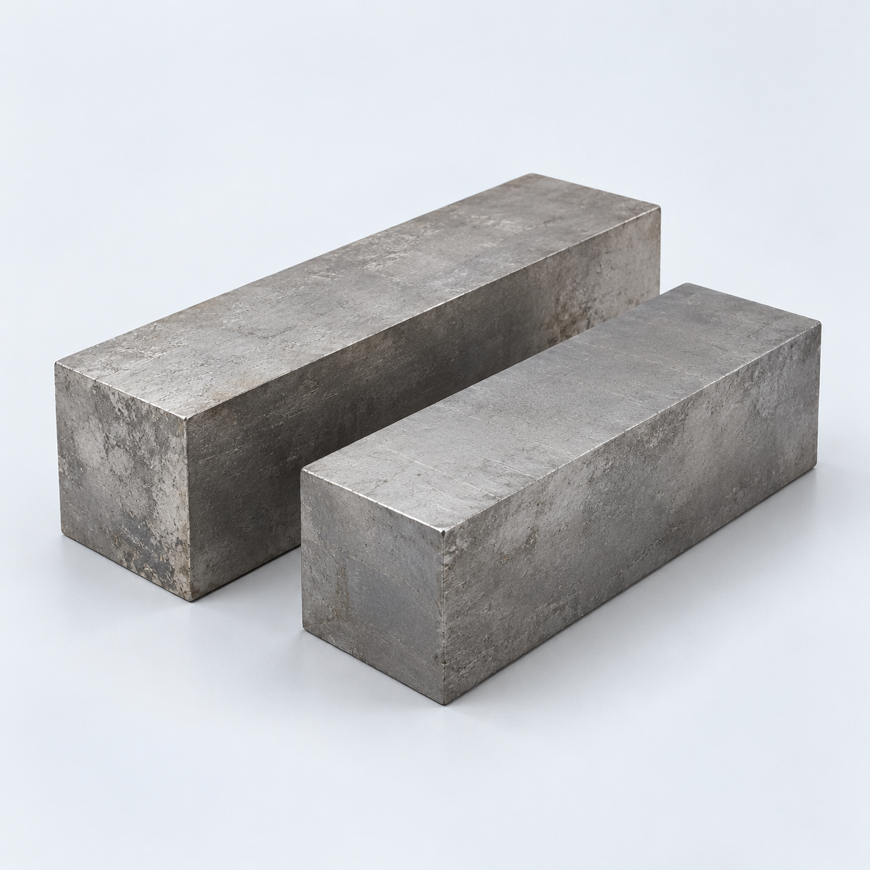 TitaniumReview grade and part geometry›
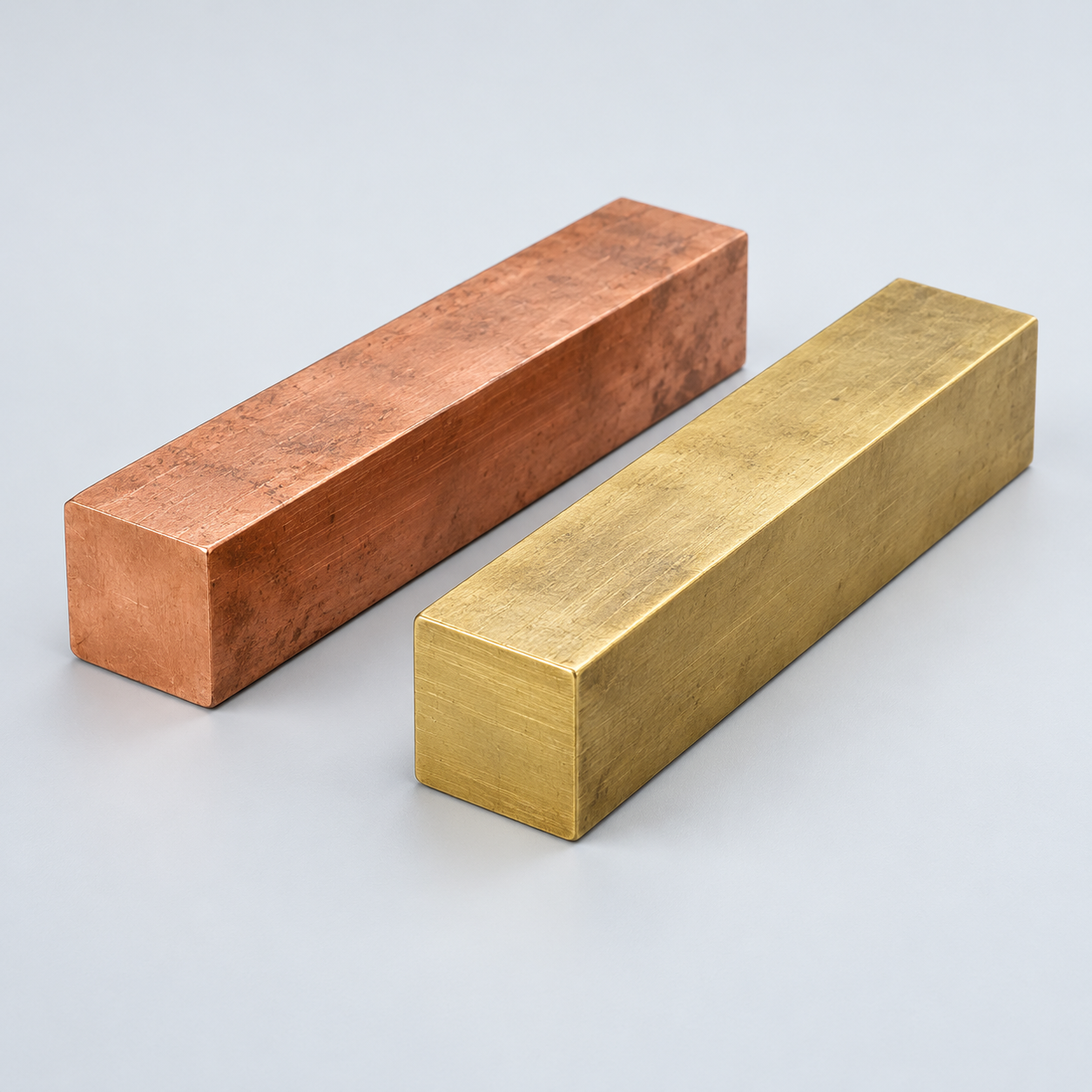 Copper & Brass & BronzeDiscuss conductivity and machining›
Match your polymer to function, process and environment.
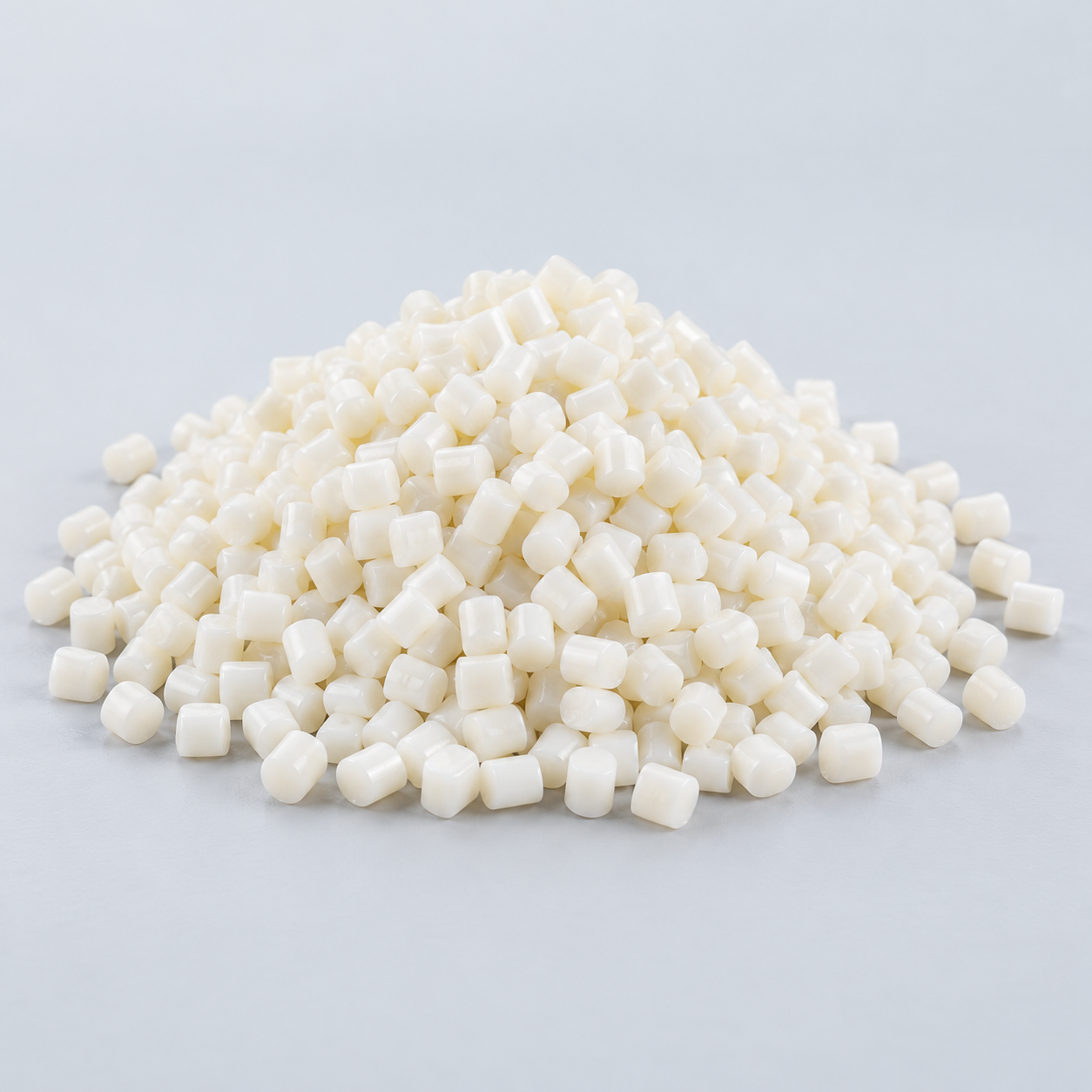 ABSReview enclosure and molding needs›
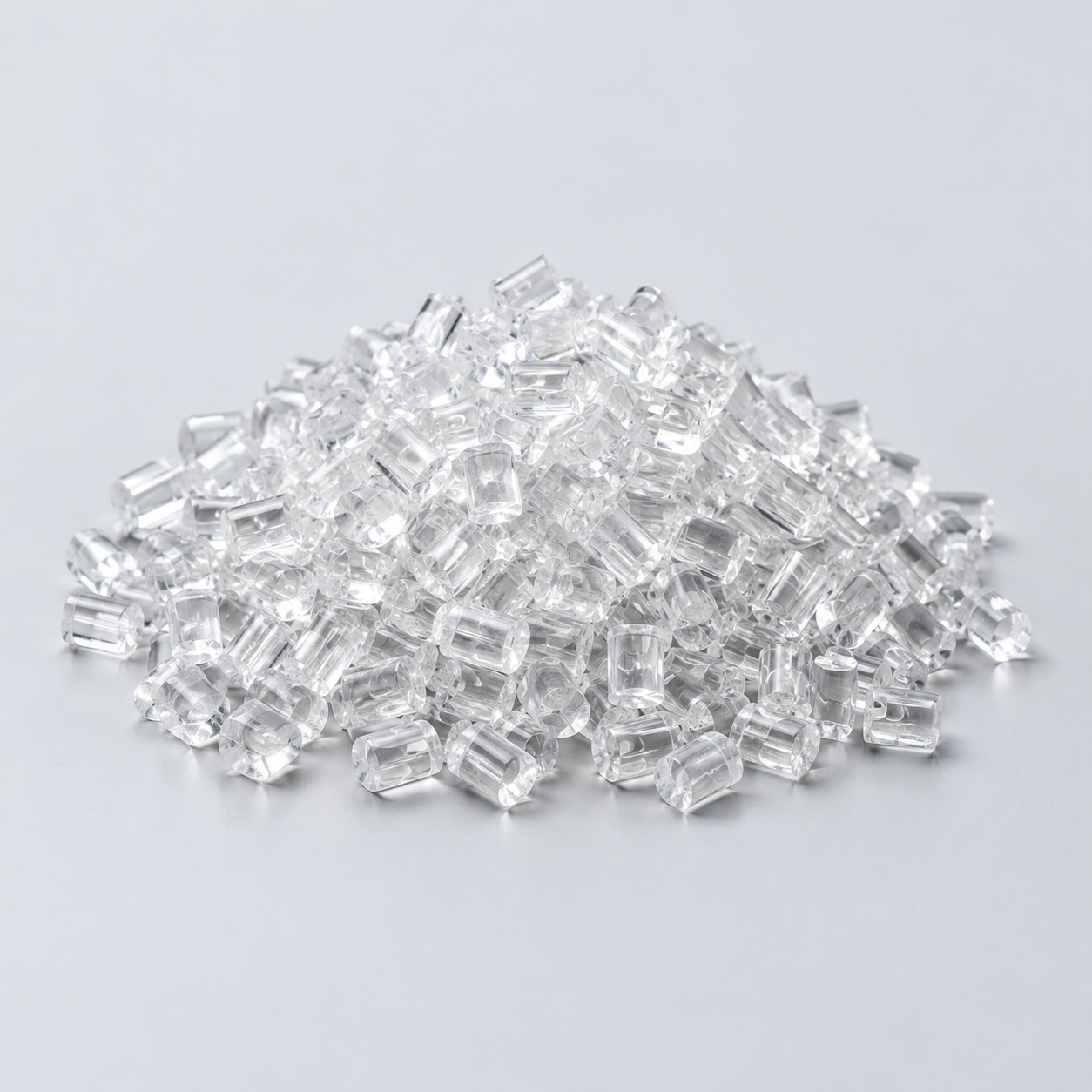 Polycarbonate (PC)Discuss clarity and impact needs›
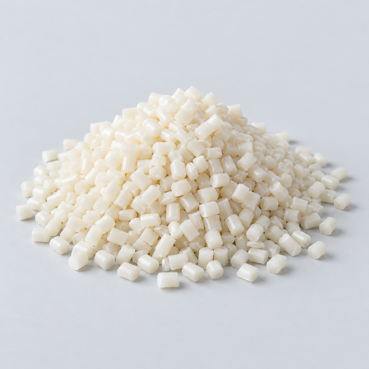 Nylon (PA)Review moisture and wear conditions›
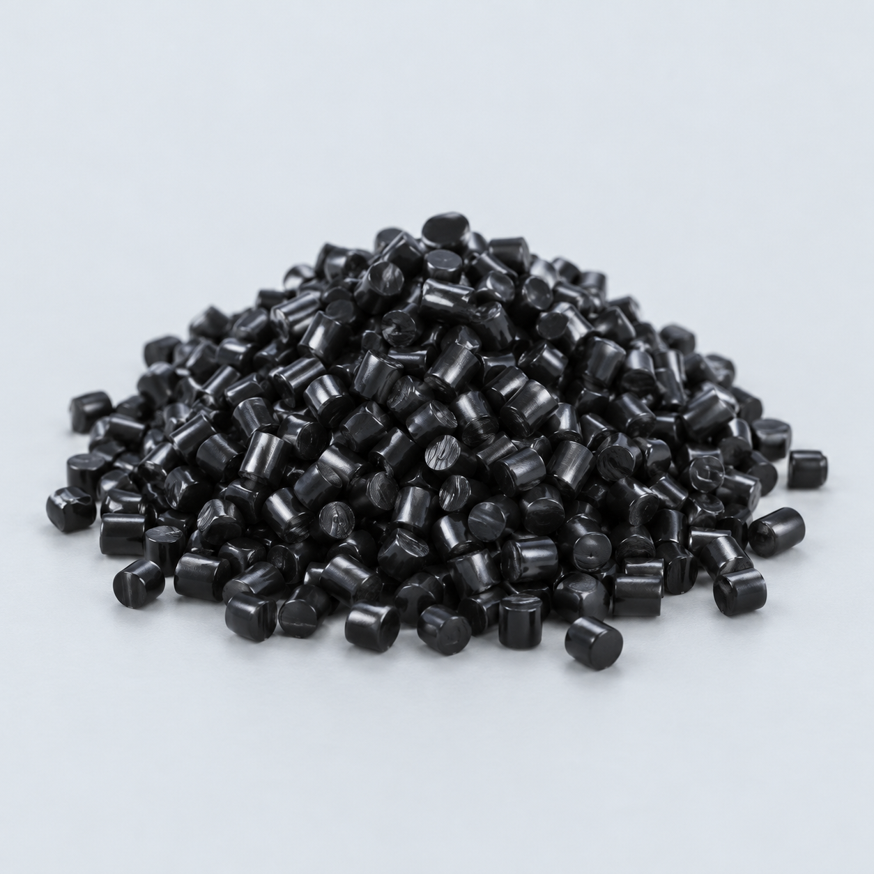 POM / AcetalReview fit and sliding features›
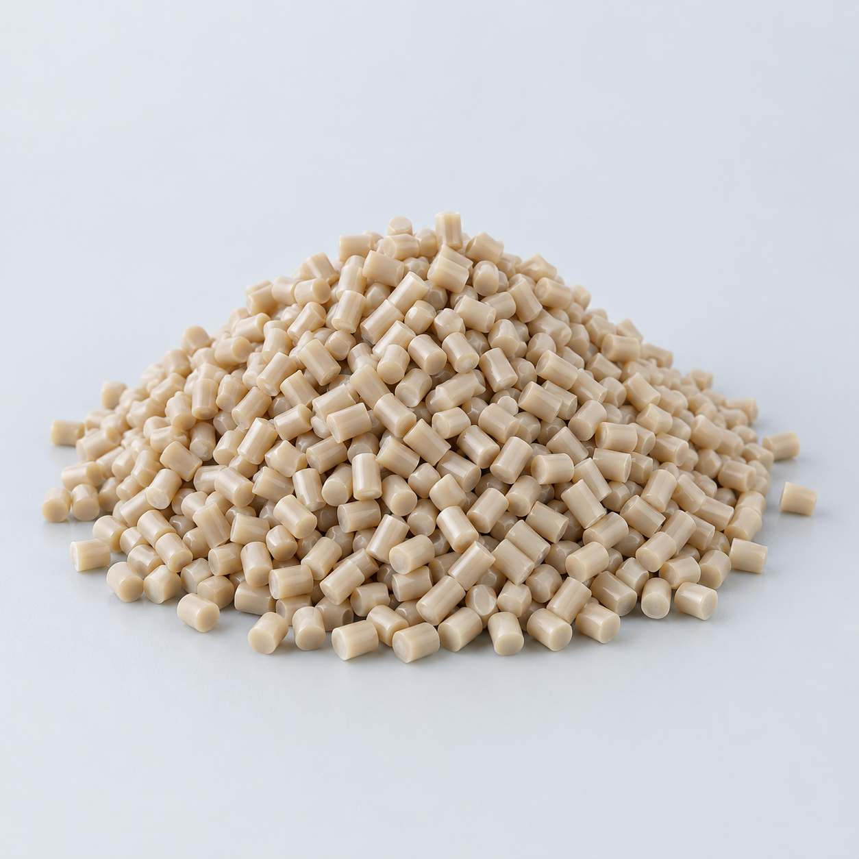 PEEKDiscuss operating conditions›
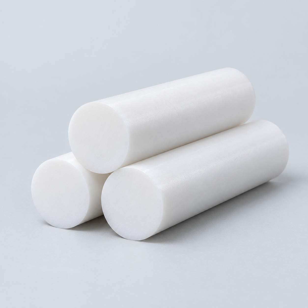 PTFEReview friction and chemical exposure›
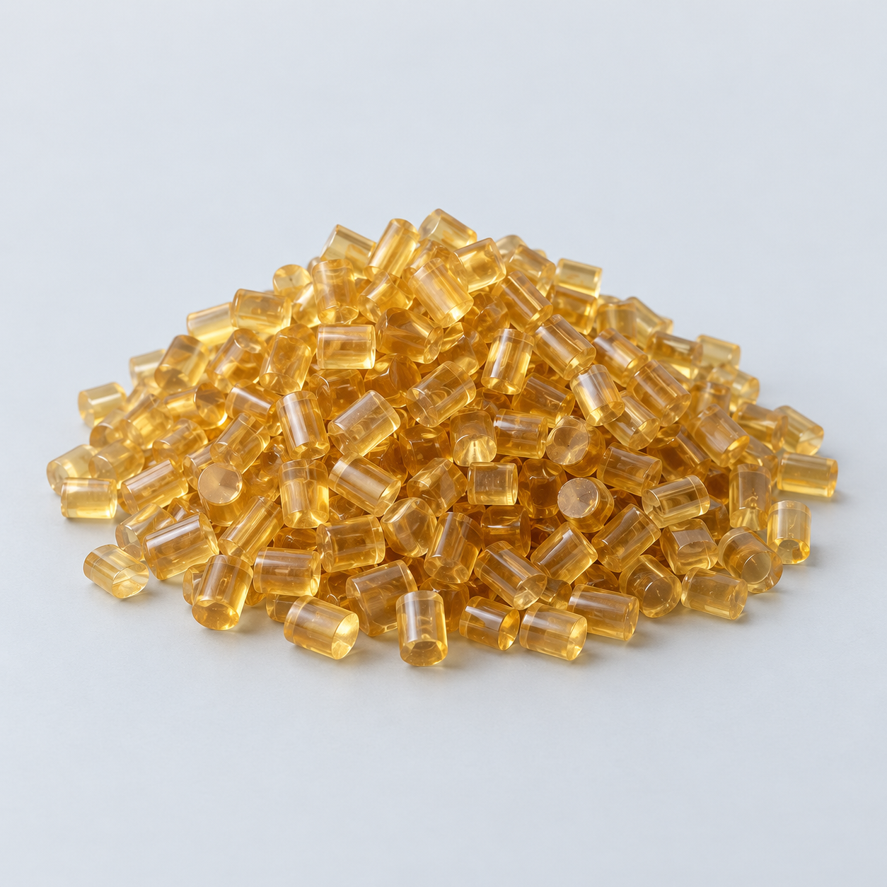 ULTEM / PEIDiscuss thermal and electrical needs›
Confirm grade availability and application requirements.
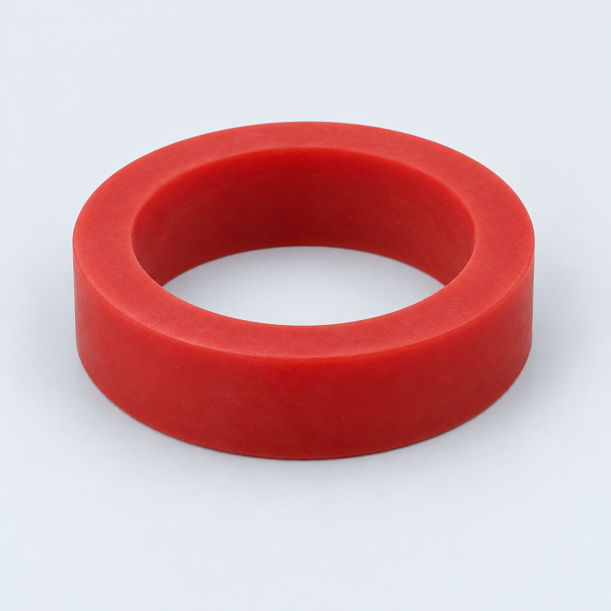 Silicone / LSRDiscuss flexible component needs›
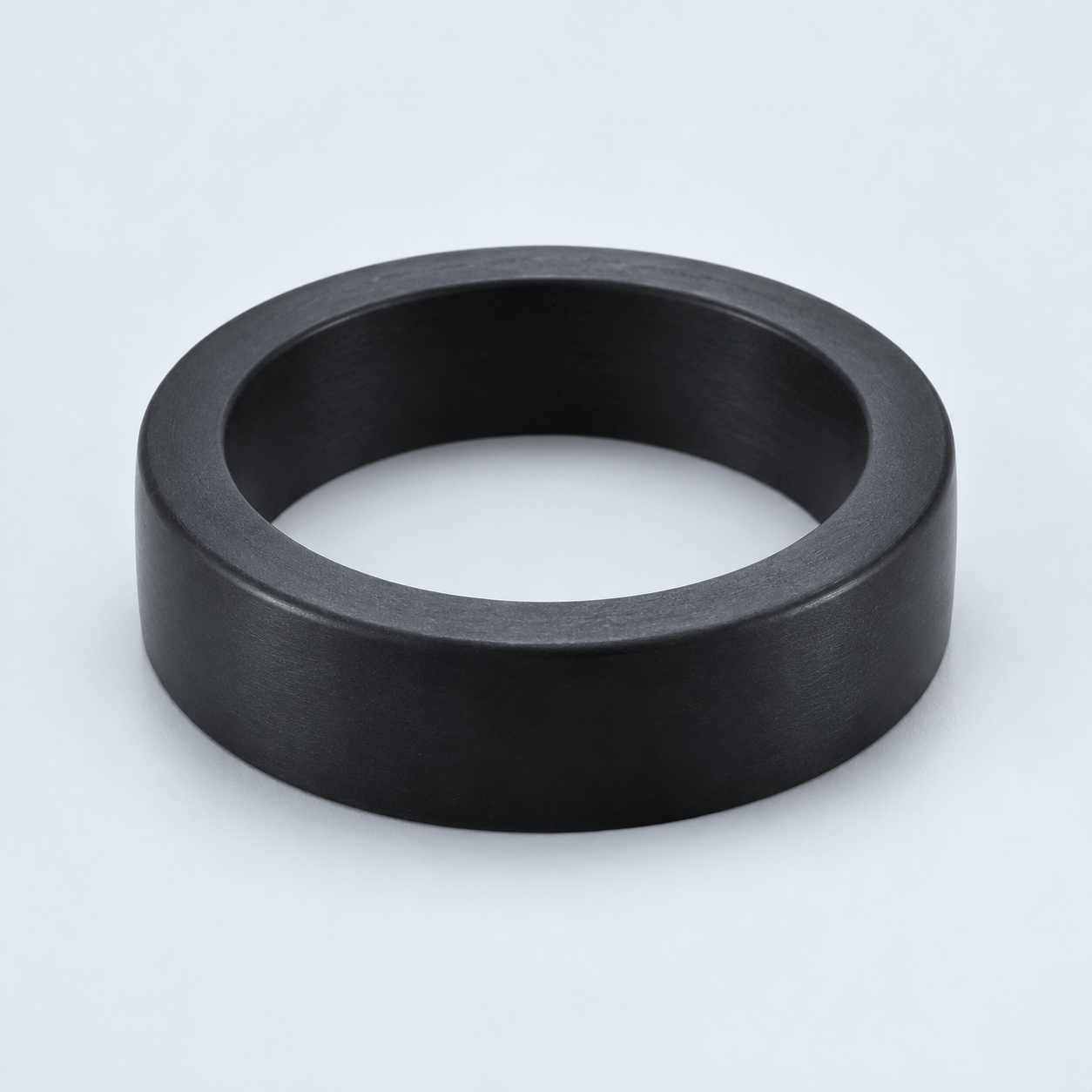 TPU / TPEReview flexibility and processing›
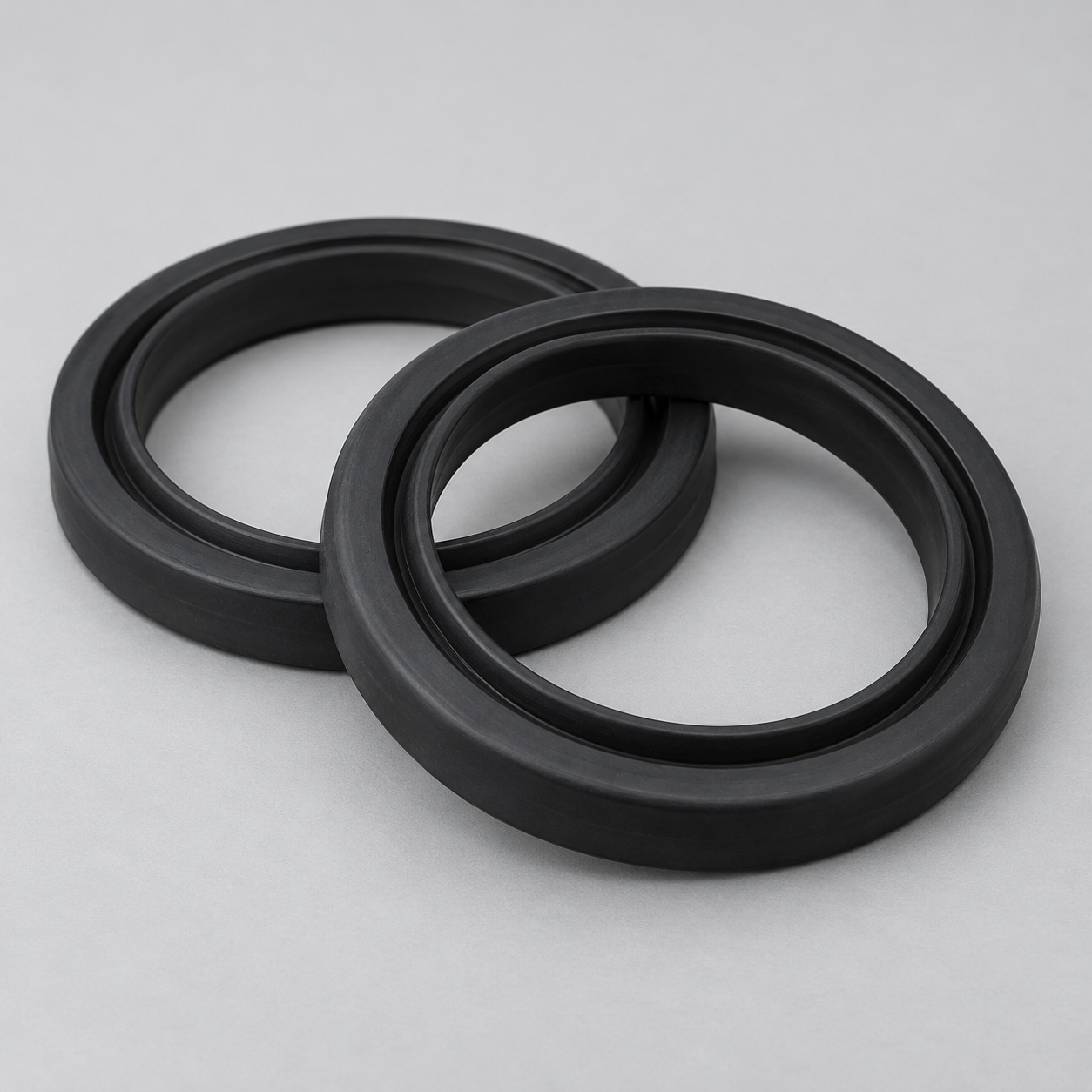 EPDMReview weathering and chemical exposure.›
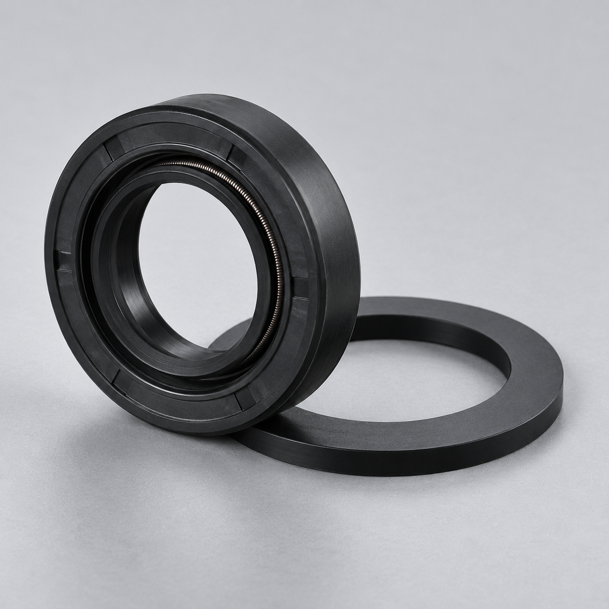 NBRReview oil and fuel exposure.›
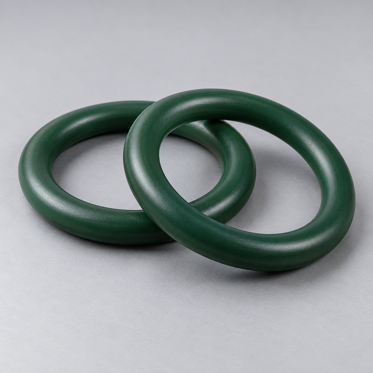 FKMReview temperature and chemical exposure.›
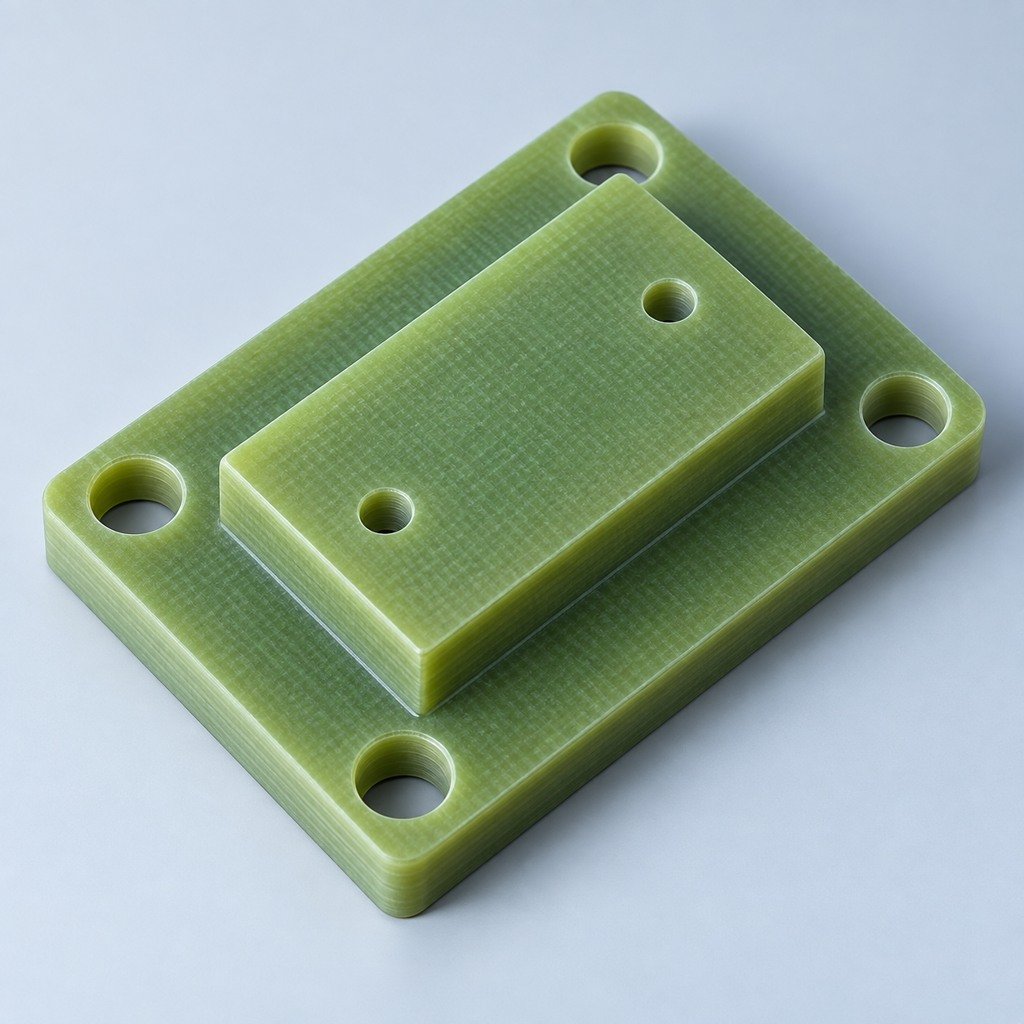 G10 / FR4Review insulation and laminate needs›
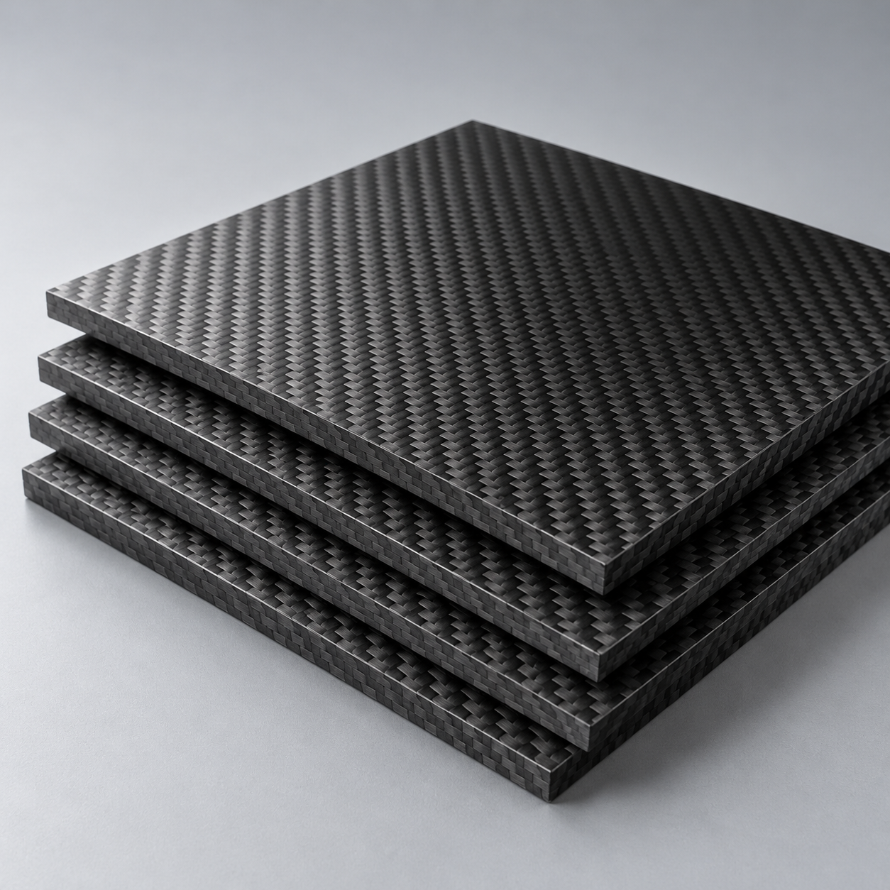 CompositesReview stiffness, weight and laminate.›Customer-Specified MaterialsConfirm your grade and requirements.›Other Specialty MaterialsDiscuss your application and grade.›
Practical guidance for your part geometry and material decisions.
Prepare your process, budget and sourcing questions.
Build your knowledge before production.
Learn who we are and how we operate.
Find our U.S. support team or start a conversation.
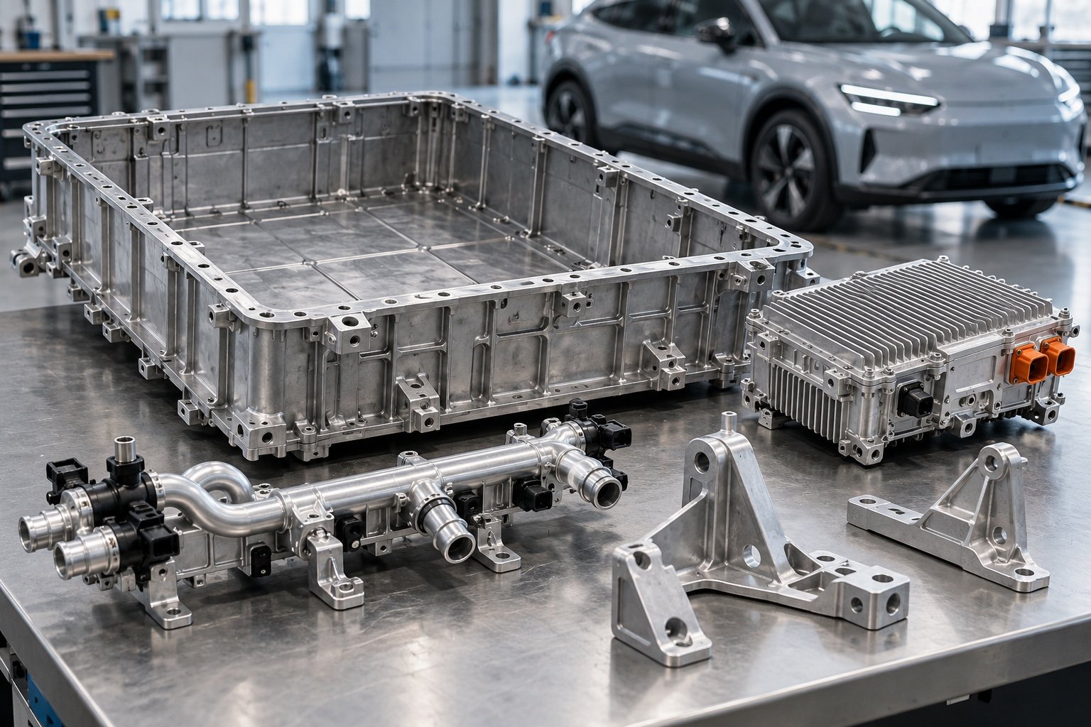
For your electric vehicle parts CNC machining project, define enclosure fits, coolant interfaces and mounting datums before release. Separate the part drawing from battery, electrical and vehicle-system validation.
Your interfaces · Your acceptance criteria · Your controlled revision
For your EV battery enclosure manufacturing brief, distinguish empty mechanical components from a complete battery pack.
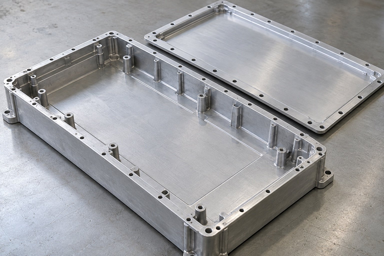
Define tray and lid geometry, seal lands and fastener locations.
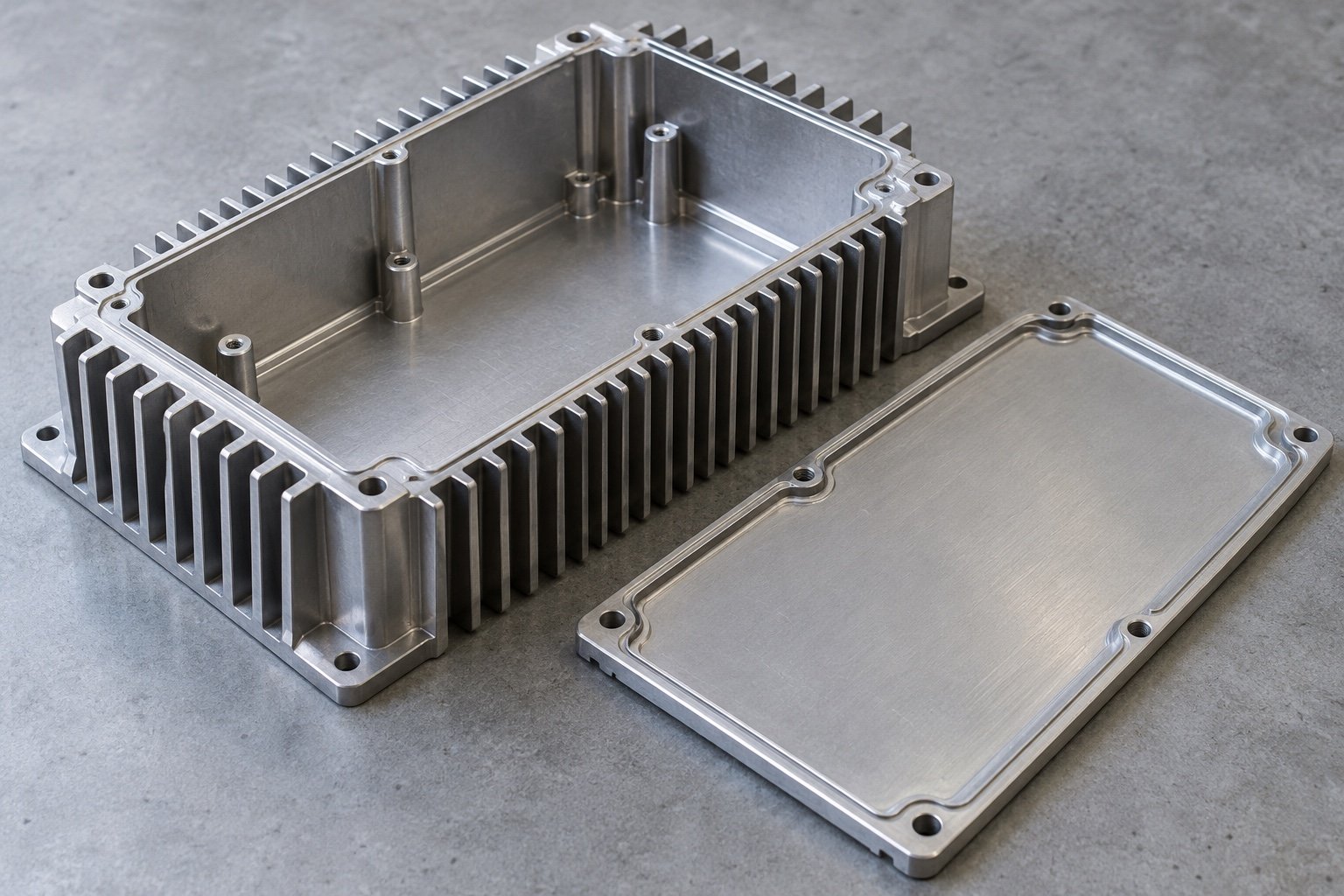
Review cover fit, mounting datums and specified thermal interfaces.
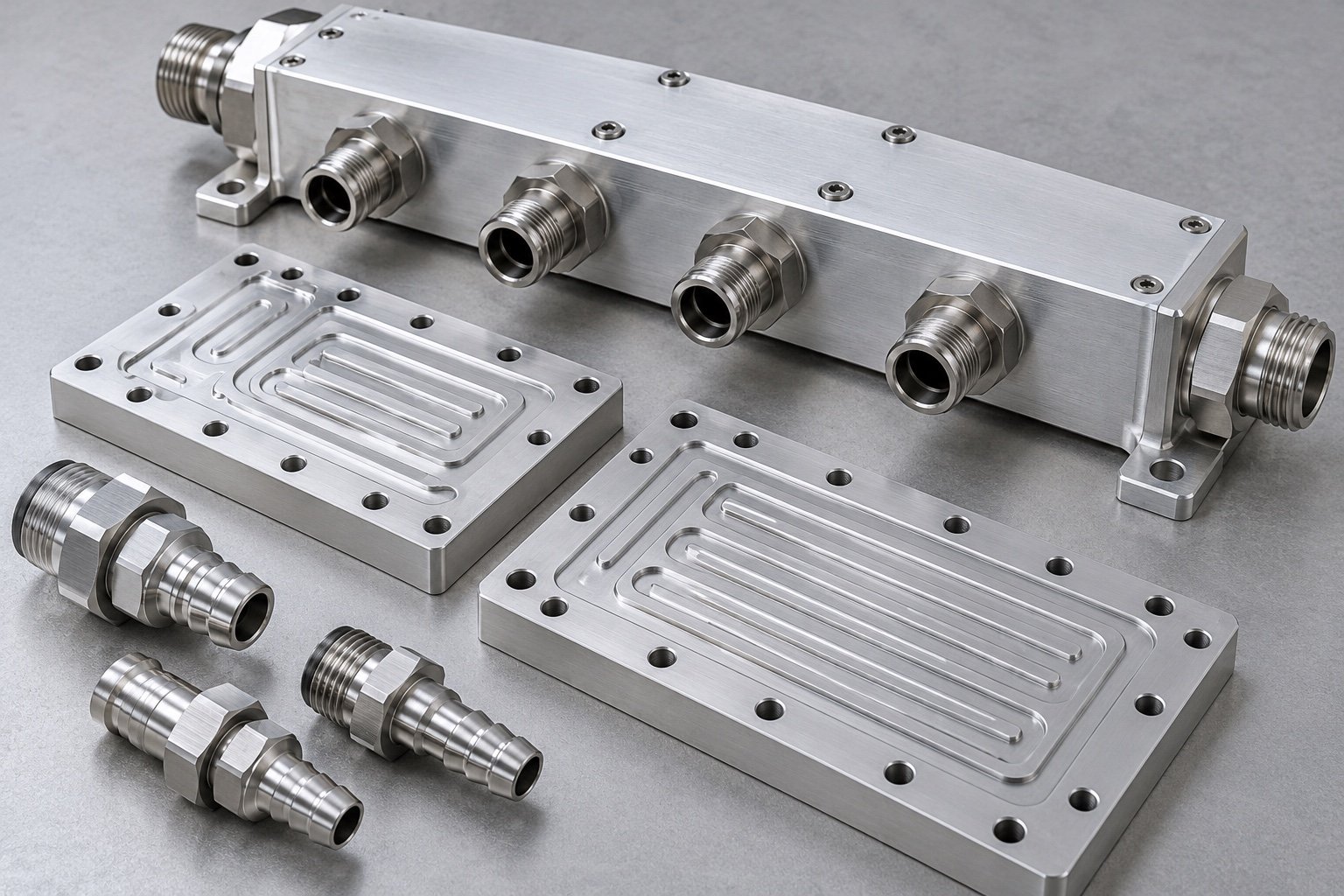
Specify port threads, sealing details and your required leak-test scope.
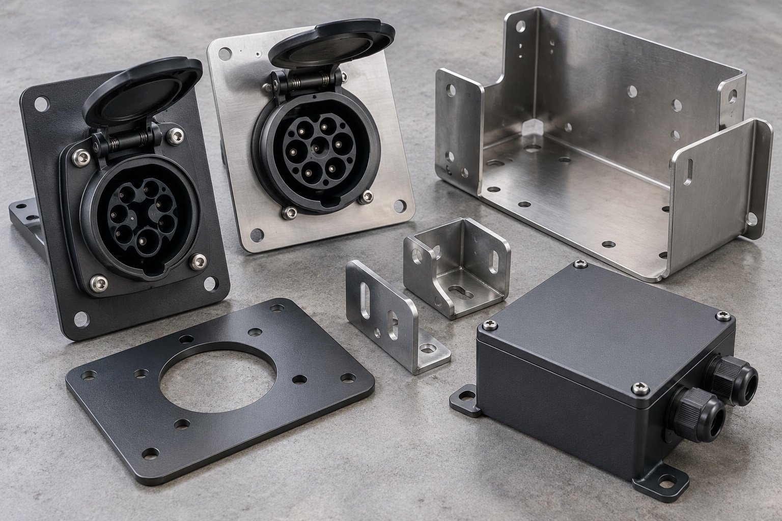
Set connector cutouts, cable clearances and attachment features.
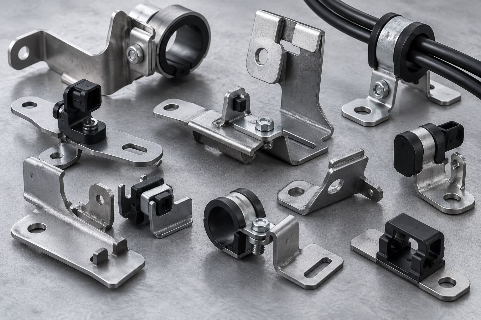
Review locating features, service access and protected surfaces.
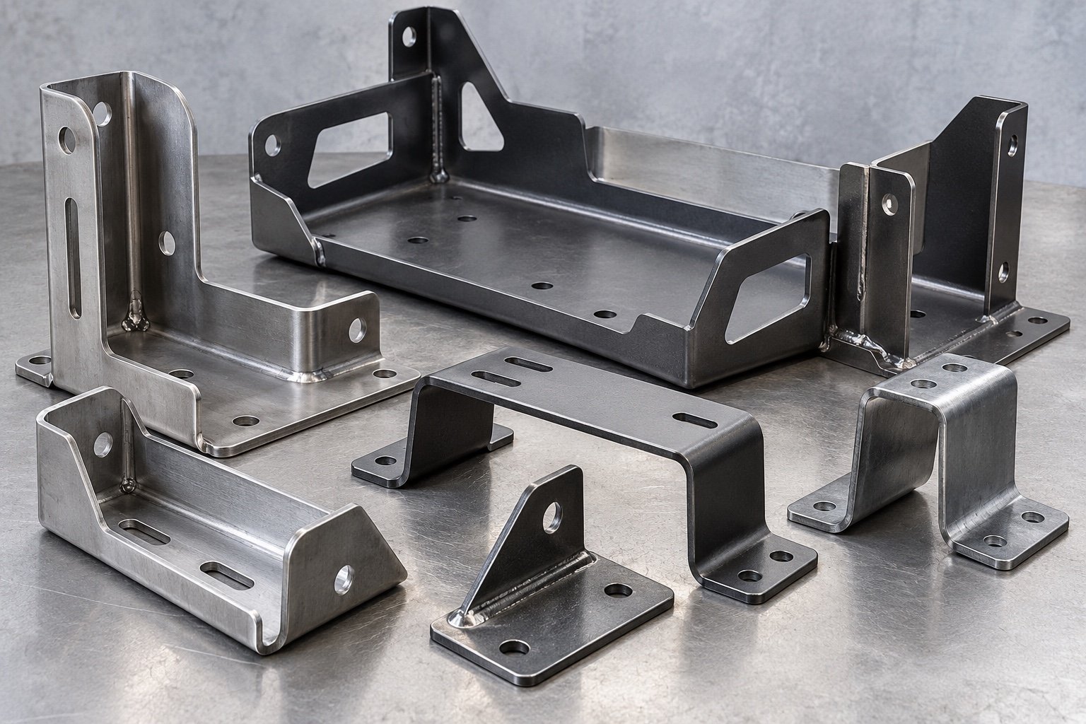
Confirm installed envelope, assembly datums and fixing access.
Your brief for CNC machining for the electric vehicle industry should include CAD, full material condition and the features you need inspected. Review EV inverter housing machining requirements with your mating components.
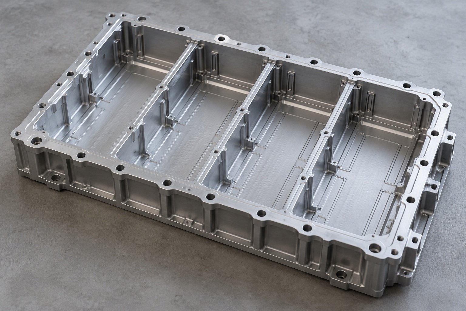
Pockets, mounting bosses and lid attachment.
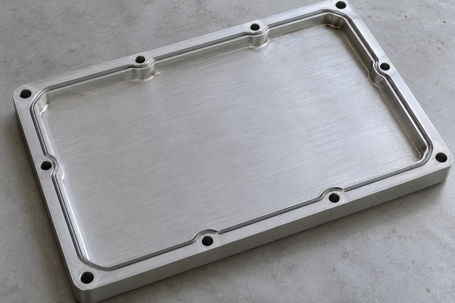
Seal lands, perimeter holes and final flatness requirements.
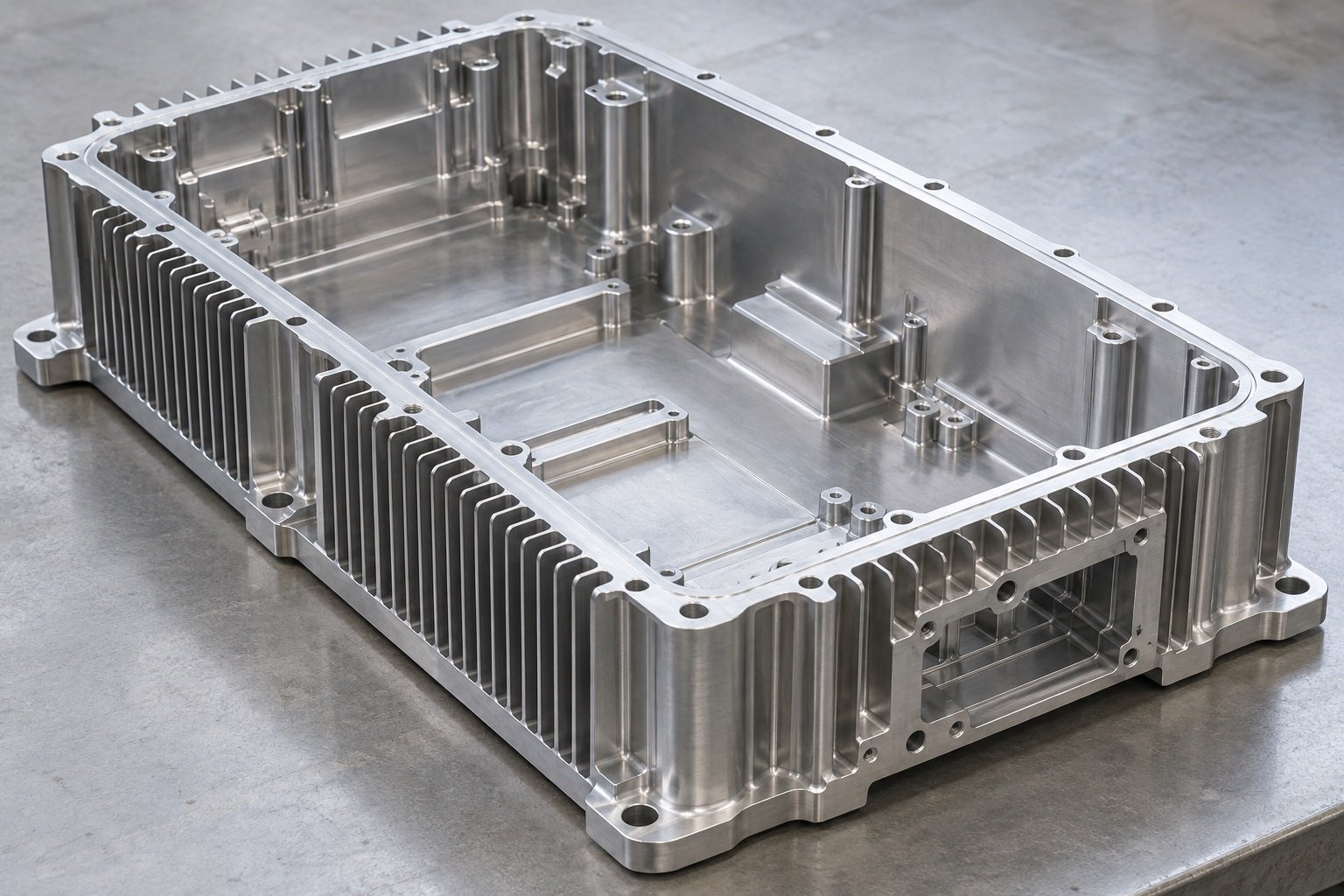
Cover fit, fins and internal component clearances.
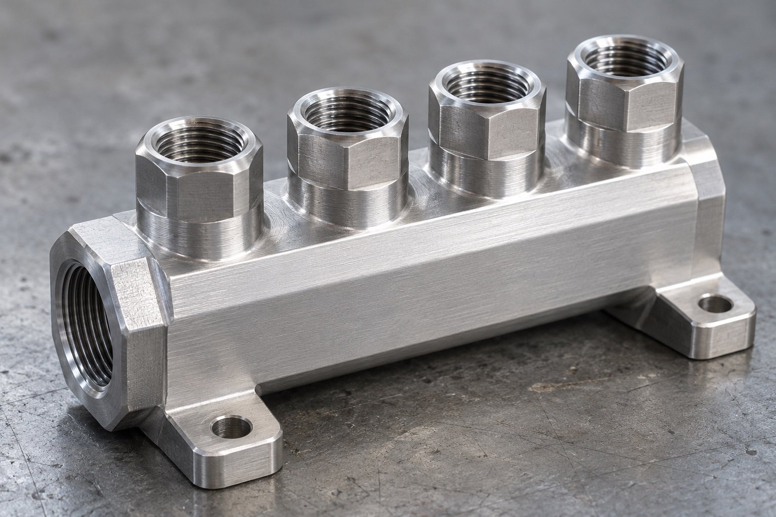
Port location, thread specification and sealing geometry.
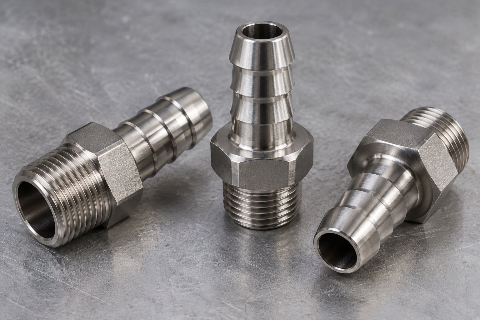
Hose or thread interfaces and specified material.
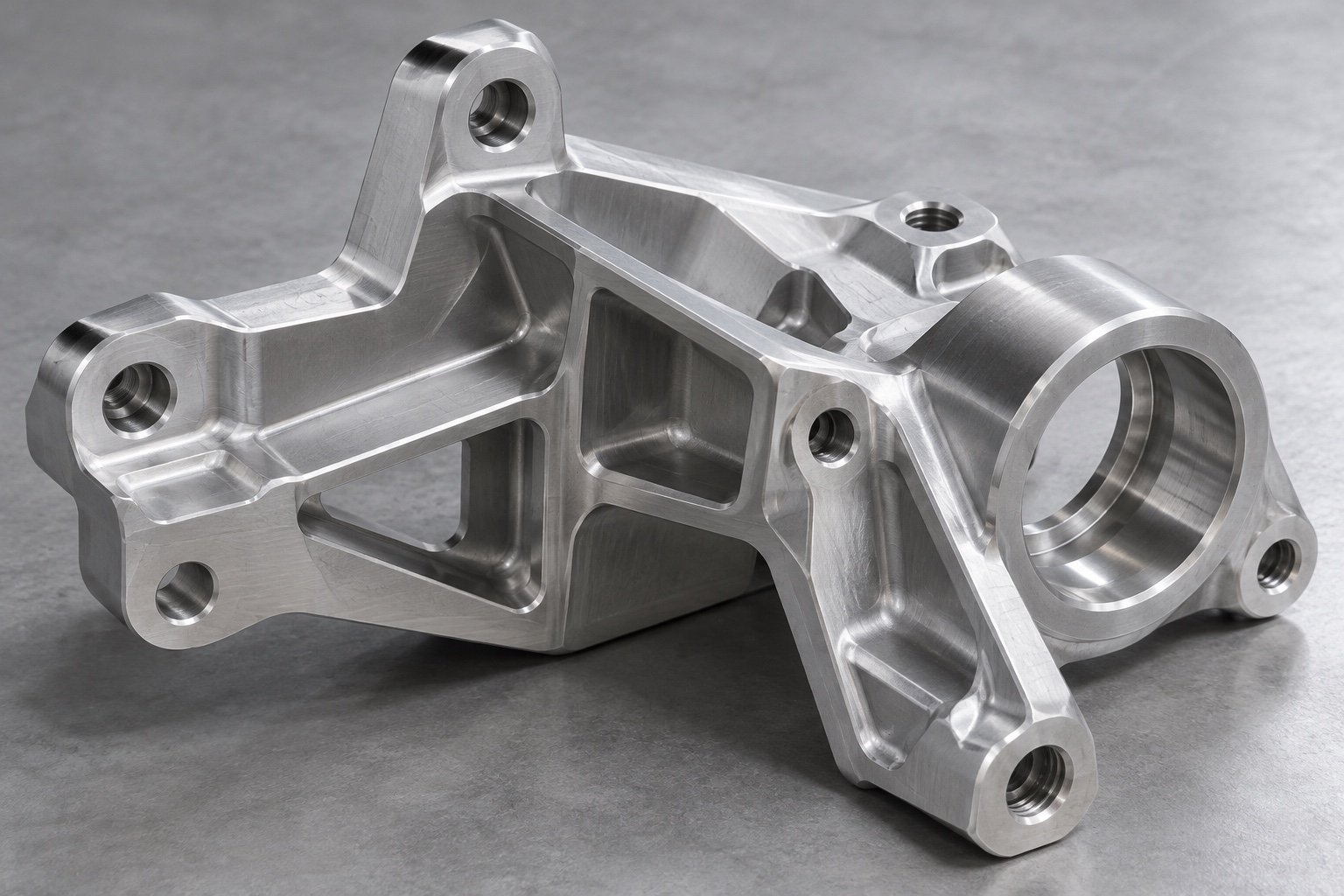
Locating datums, fixing bores and assembly access.
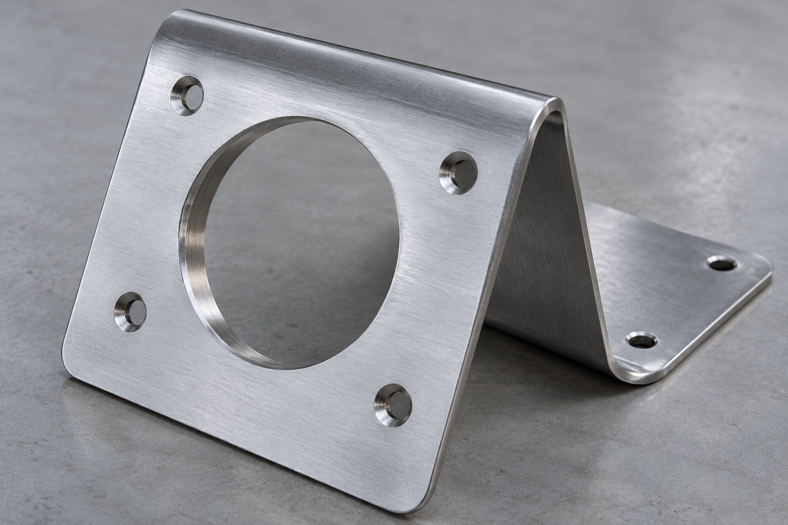
Connector cutouts, bends and protected edges.
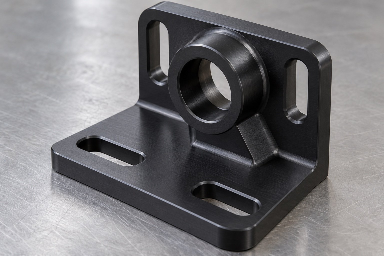
Adjustment slots, locating faces and service clearance.
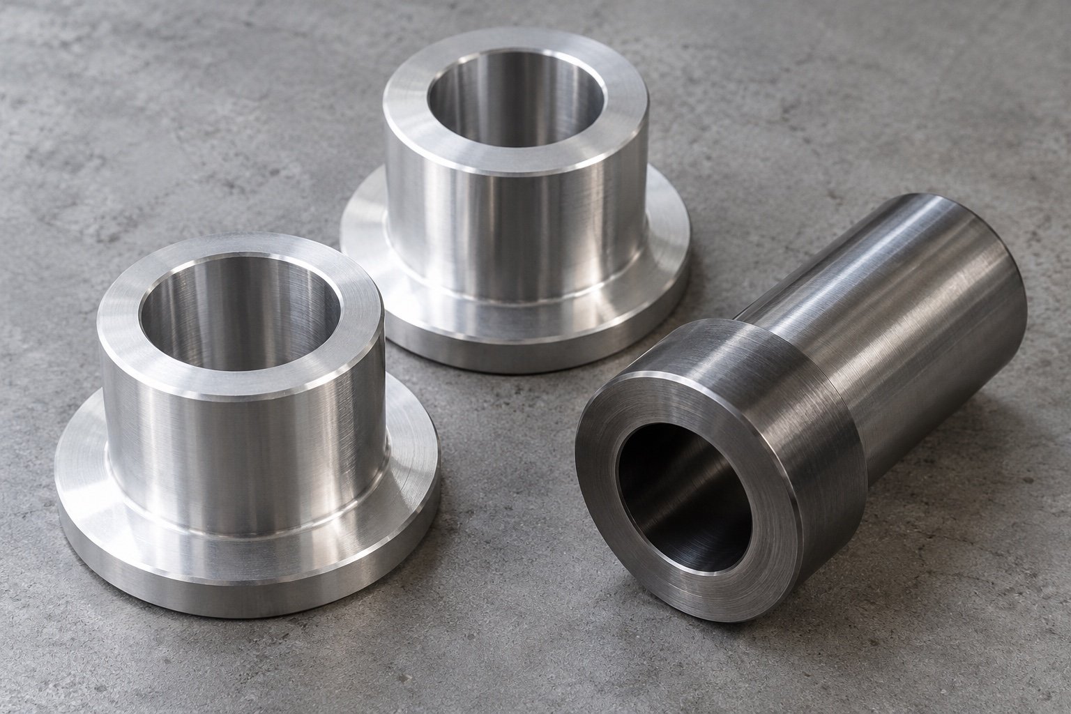
Shoulder diameter, thickness and mating fits.
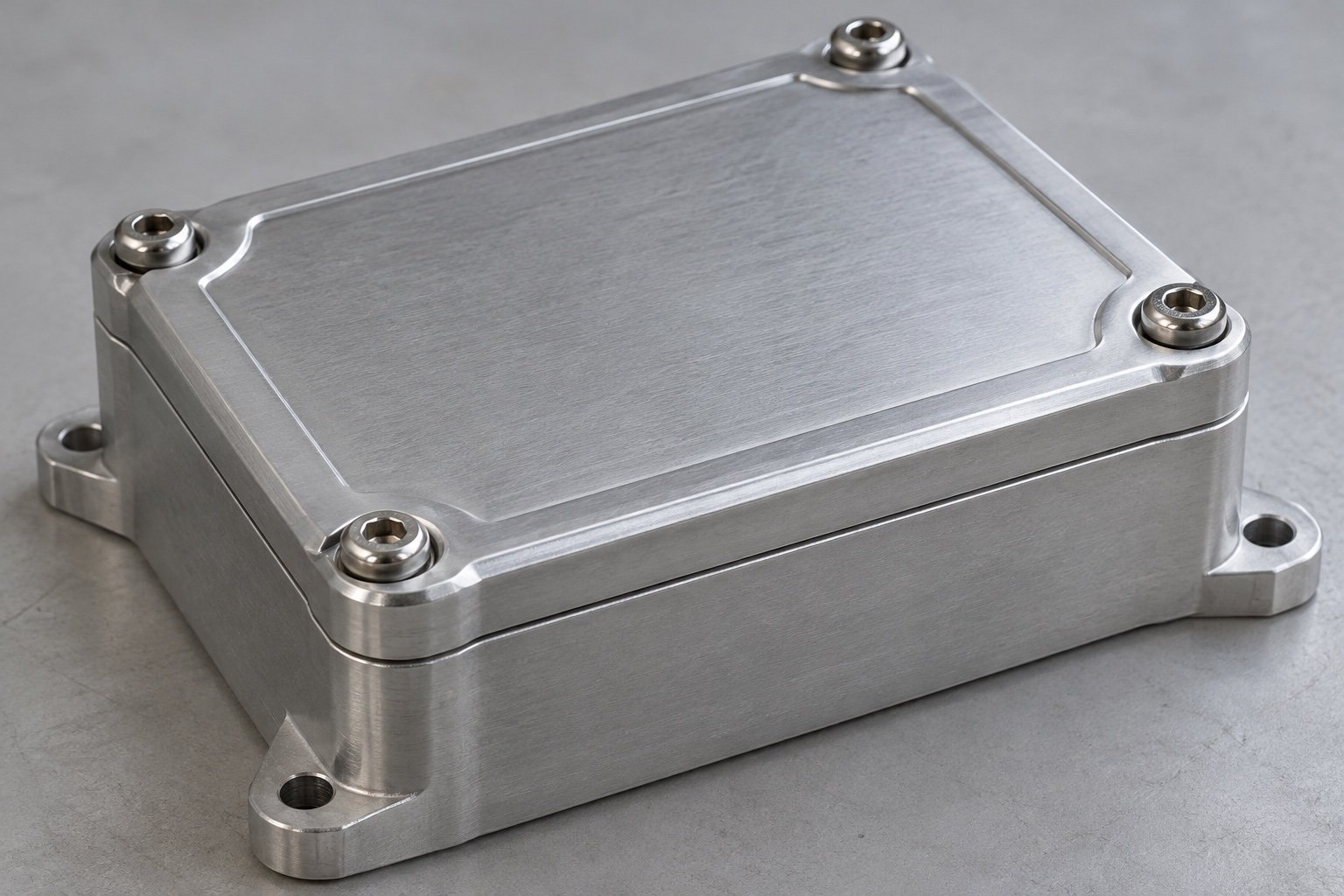
Fixing pattern, cable clearance and protected interfaces.
Compare your drawing geometry, seal lands, coolant ports, electrical clearances, production volume and inspection requirements before selecting a route.
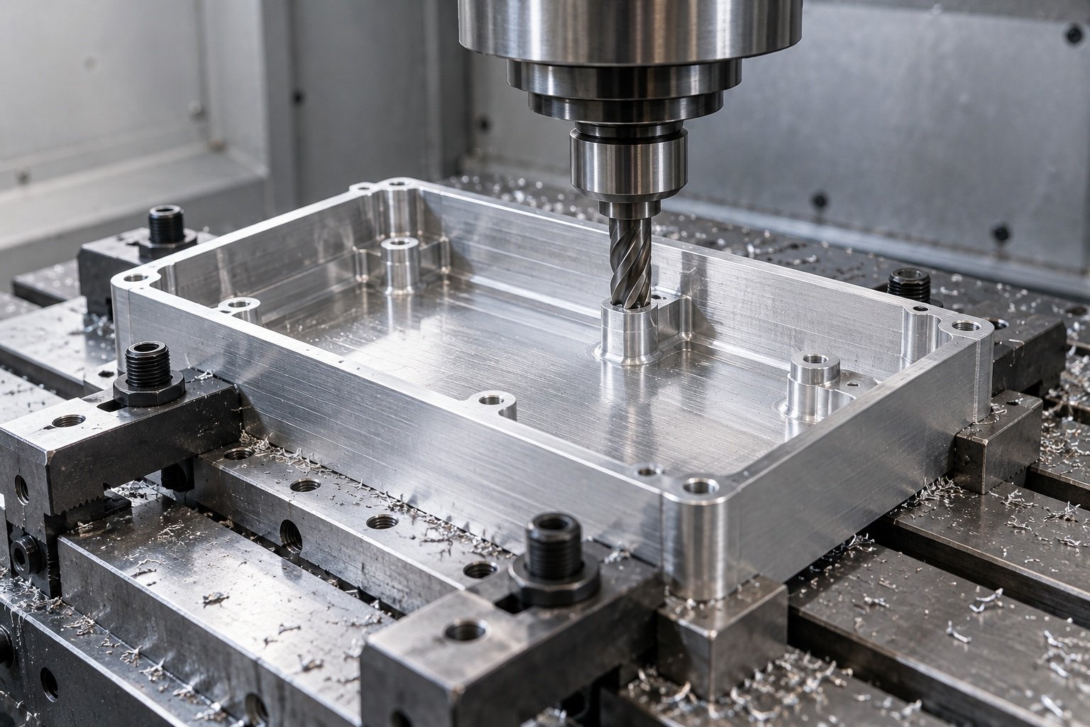
Mounting bores, complex pockets and accessible tool paths. Your final process is confirmed after drawing review.
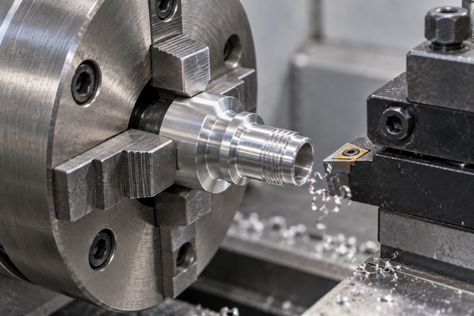
Concentric features, shoulders, pin bores and spacers. Your final process is confirmed after drawing review.
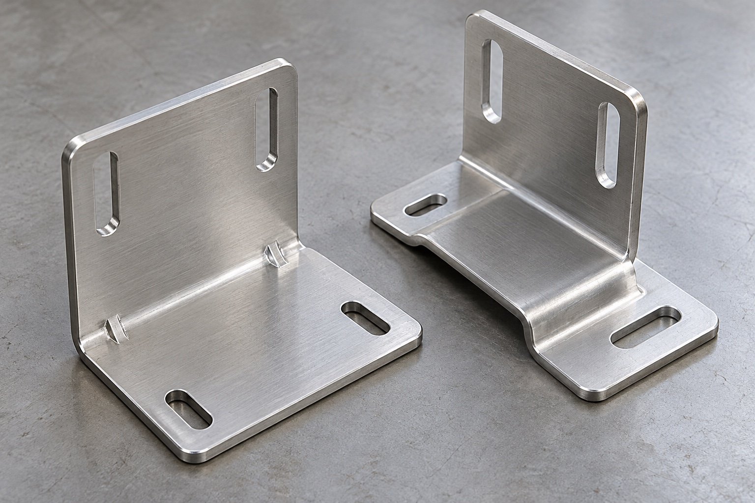
Bends, slots, mounting envelopes and coating allowances. Your final process is confirmed after drawing review.
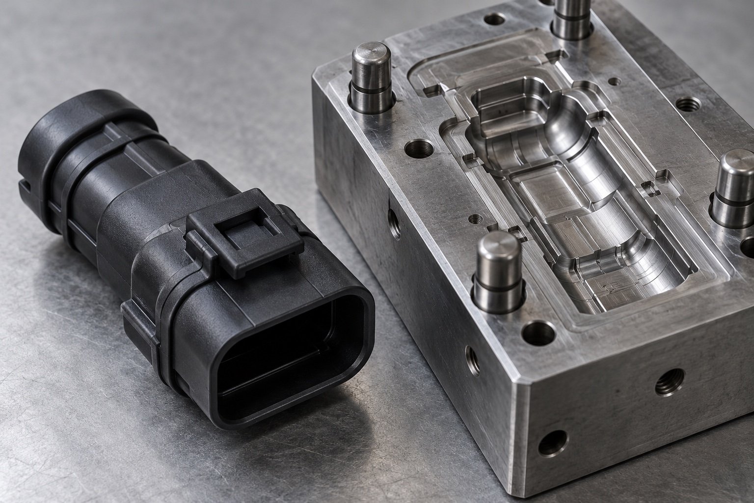
Review resin, wall thickness, clips and tooling ownership. Your final process is confirmed after drawing review.
Define corrosion exposure, appearance and protected interfaces. Your final process is confirmed after drawing review.
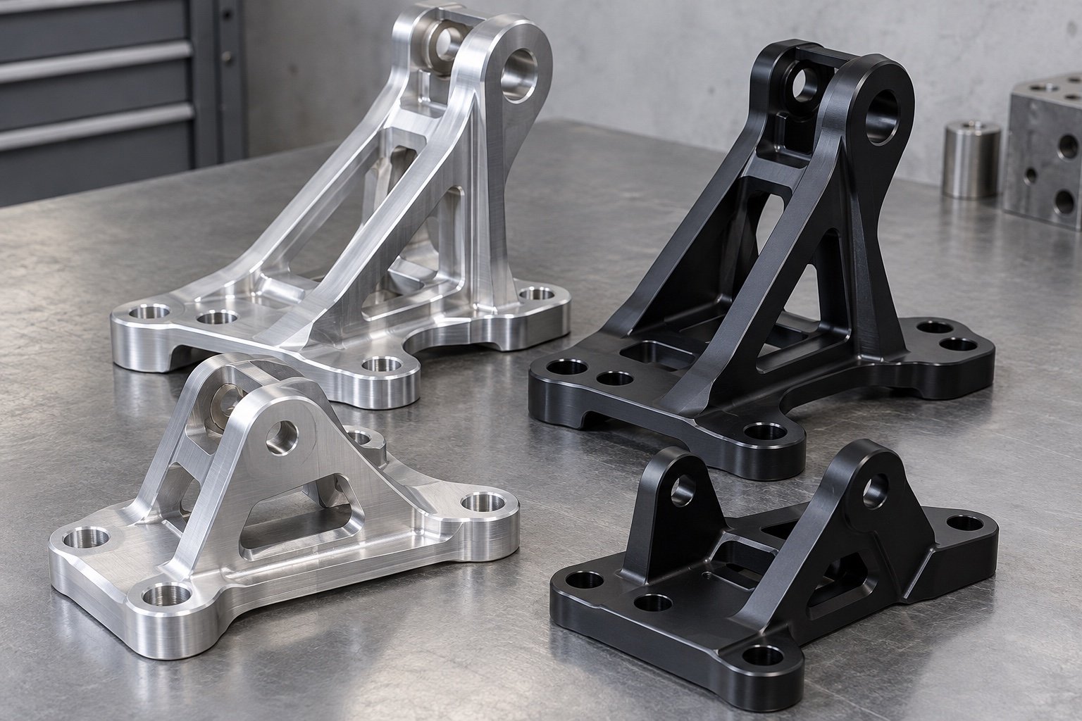
CAD, enclosure interfaces and released revision.
Grade, condition and final finish.
Sample, initial order and repeat demand.
Critical dimensions and required records.
Send your drawing, quantity and acceptance requirements.
Material chemistry alone cannot establish enclosure sealing, electrical insulation or thermal performance.
Specify the complete alloy, temper and stock form. EN AW wrought grades and EN AC cast grades require separate review.
Identify seal lands, electrical bonding areas and thermal contact faces. Define coating masks and final dimensions.
State any leak, pressure, insulation or environmental tests separately, including method and acceptance criteria for quotation review.
A dimensional inspection does not establish battery-pack safety, an IP rating or whole-vehicle approval.
Illustrative review sequence · no dimensions or test results implied.
Define mating datums, seal lands and port geometry.
Mark dimensions, threads and surface requirements to report.
Agree leak or other testing only where specifically required and quoted.
Control material, casting, machining and coating changes.
Define what the mechanical component must meet before committing to repeat production.
Include material, revision, quantities and retained component geometry.
Compare machining, tooling and finish around your acceptance requirements.
Review dimensional records and complete your application-specific validation.
Keep drawing, process changes, packing and required records connected.
For your EV mechanical parts program, distinguish where the part is made from where your project communication is supported.

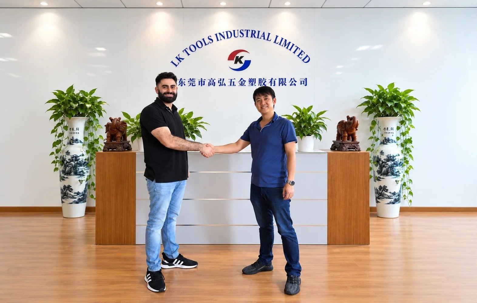
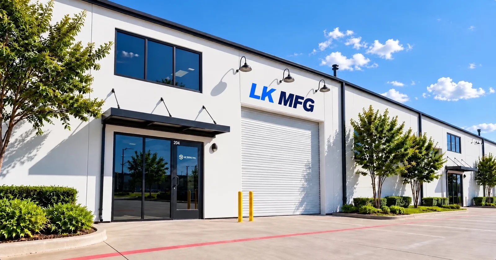
Agree who owns the drawing and sample approval.
Confirm packing, delivery terms and import responsibilities.
Discuss local coordination and any inventory arrangement.
Genuine company and customer-discussion photographs. Manufacturing in China; U.S. support does not mean U.S. manufacture or a default local stock program.
Factory & Operations →Upload the drawing revision, material, finish and quantities. Identify seal lands, coolant ports, protected interfaces and any required test method.
Clarify manufacturing scope, interfaces and verification before production.
This page covers custom mechanical components such as empty trays, housings and brackets. Cells, BMS integration, pack certification and vehicle approval are not implied.
Supply CAD, material condition, cover and connector interfaces, final dimensions, finish masks, quantities and any required test method with acceptance limits.
No. The finished assembly, gasket, fastening, ports and test conditions determine sealing performance. Specify the required verification separately.
Submit the complete drawing with bearing fits, concentric datums, mounting features and required records for a project-specific review.
Identify the mating surfaces, final flatness, surface finish, coating masks and your thermal interface material. Part geometry alone is not a thermal performance result.
Provide both quantities and the validation objective. Any process or material change must be reviewed and approved before the production release.