




































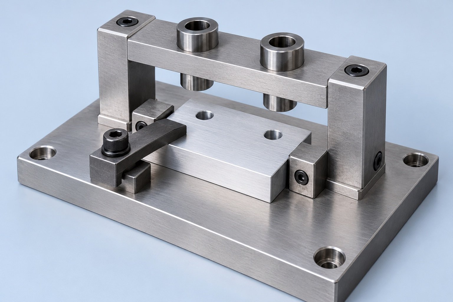
Your jig and fixture requirements should start with the operation, the part revision and the surfaces that establish position. A useful workholding brief explains what must stay accessible, what must be protected and how your team will accept the completed tooling.
A jig usually locates and holds a workpiece while also guiding a cutting tool. A fixture locates and holds the workpiece while the machine or another system controls the tool path. For example, a drill jig can use guide bushings; a milling fixture leaves the cutter path to the machine. This distinction is described in KEYENCE’s explanation of manufacturing and inspection fixturing.
Decide what the tooling needs to control
Begin with the job your tooling must perform rather than requesting a particular shape. Your team may need to drill a repeated hole pattern, expose several faces for milling, support an assembly while fasteners are installed, or present a part consistently for inspection. Each task creates a different access and acceptance problem.
| Question | Jig example | Fixture example |
|---|---|---|
| What guides the tool? | A drill bushing physically guides a drill. | The machine controls cutter movement. |
| What needs access? | The tool must enter and clear the guide. | The planned cutter, probe or assembly tool must reach the required features. |
| What should your brief include? | Hole requirements, tool details and bushing service needs. | Setup orientation, locating features and the required working envelope. |
The label alone does not define the design. Attach a marked drawing or setup sketch showing your intended operation and ask the tooling supplier to identify any assumptions before manufacture.
Separate locating, support and clamping
Locators establish the part’s position. Supports provide a reaction beneath the workpiece, while clamps keep it seated. Carr Lane’s fixture design principles explain the relationship between locating and clamping and the need to avoid redundant location. Its work-support guidance also describes how inadequate support can allow cutting forces to deflect a part.
For your review, identify which drawing surfaces or holes are the references, which incoming features may vary and where a clamp may contact the part. Do not leave a supplier to infer that a convenient raw edge is a functional datum. If a cosmetic face cannot be marked, say so and agree how it will be protected.
Review access before approving the model
Ask for a setup view with the workpiece, clamps and intended tools shown together. Check the approach to each required feature, the space needed to change a tool and the route for loading and removing the part. An attractive empty fixture model can conceal a difficult loaded setup.
Include the inspection method in that discussion. A feature that is easy to machine may be difficult to probe with the part clamped. Your acceptance plan should state which checks happen in the fixture and which happen after removal. Tooling approval should not silently replace the finished-part drawing requirements.
Choose materials around the actual environment
Give the supplier the expected coolant, cleaning method, contact surfaces and any temperature or chemical exposure. Identify parts that should be replaceable, such as contact pads, locating elements or drill bushings, and request an agreed spare-parts list where maintenance matters.
Machined metal, polymer contact elements and printed components may each have a role, depending on load, wear, environment and the required accuracy. A material name by itself is not enough to approve a production tool. Ask what evidence supports the proposed material for your specific operation. Any change to a locating or contact element should trigger a review of its effect on the part.
Use a trial to answer a specific question
Consider an illustrative bracket project. Your drawing identifies the mounting face and two holes as functional references, but the incoming blank has a variable outer profile. The tooling review should clarify how the bracket is located without relying on that profile, where clamping is permitted and whether the cutter can reach the required faces.
A useful trial then checks those agreed questions with representative parts. Record loading orientation, seating checks, access problems and the agreed measurement results. If several incoming conditions are permitted, identify which ones the trial represents. This example is a review method, not a promised tolerance, cycle time or production result.
Send a complete jig and fixture RFQ
- Current part CAD and drawing, including revision and relevant datums.
- The operation, machine or workstation interface, and available envelope.
- Incoming part condition, permitted variation and areas requiring protection.
- Expected use, loading method and any handling constraints.
- Tool, probe, fastener or assembly access that must remain available.
- Acceptance checks, required records and maintenance expectations.
If an input is undecided, flag it explicitly. Separate the requirements you have approved from proposals you want the supplier to evaluate. Your existing CNC machining RFQ checklist can help organize the drawing package; the tooling brief adds the setup and workholding requirements.
Questions to settle before ordering
Does every CNC setup need a custom fixture?
Discuss standard workholding first, then identify the access, support or repeat-loading problem that remains. Ask the supplier to explain why custom tooling is appropriate for your part and scope.
Can a printed component replace metal tooling?
That requires an application-specific review. State the operating conditions and acceptance requirements, then evaluate the proposed component and validation plan rather than approving a substitution from a material label.
What should accompany delivery?
Agree the fixture revision, setup instructions, acceptance record and any replaceable-component information before the order. Keep these connected to the part revision so a later drawing change can be reviewed against the correct tool.

