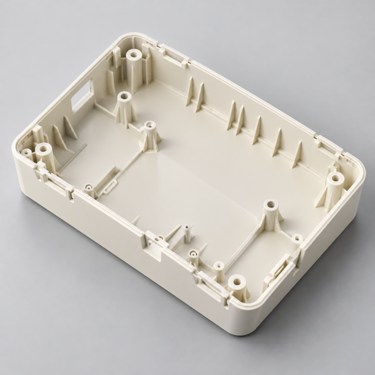
Injection Molding
Tooling and molding for your repeat plastic parts.
From prototype to production, coordinated manufacturing solutions for your custom parts.
View All Services →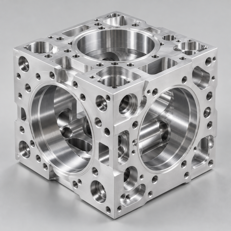
Precision parts for your tight tolerances and complex geometry.
Tooling and molding for your repeat plastic parts.
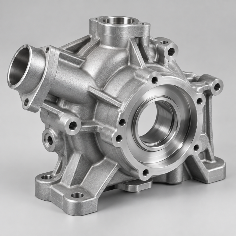
Metal casting options for your part and production volume.
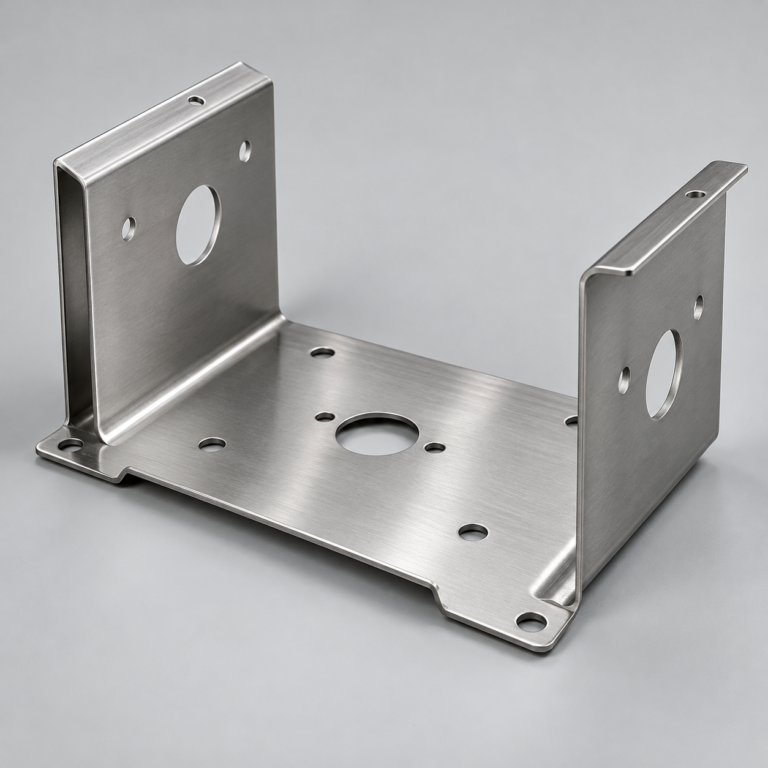
Cutting, forming and welding for your fabricated parts.
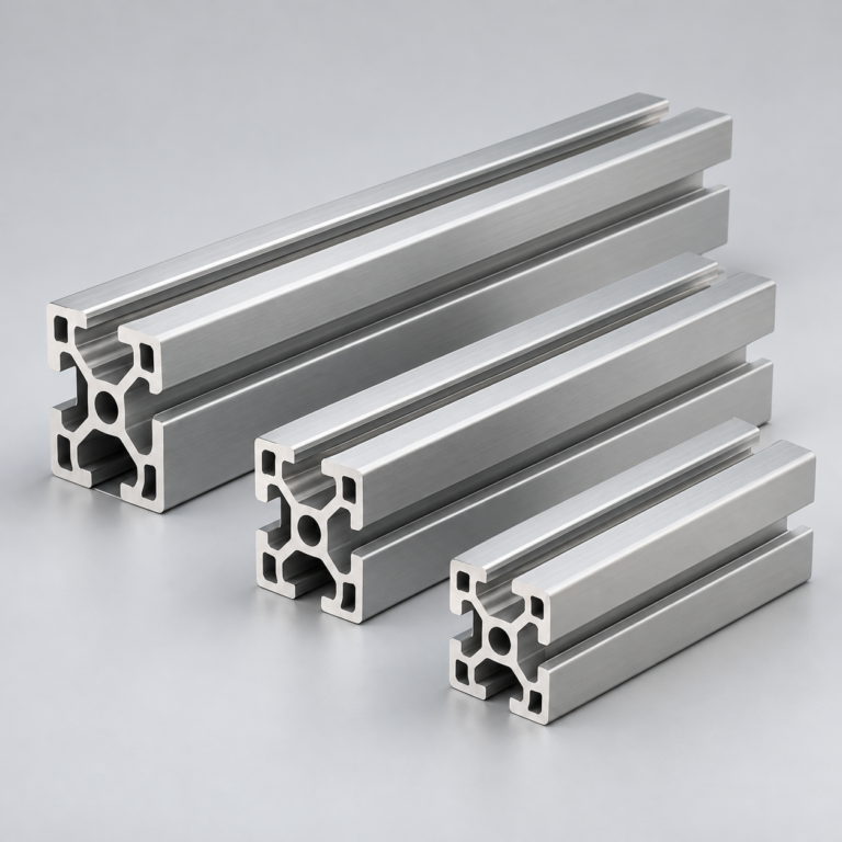
Custom profiles for your section, length and finish requirements.
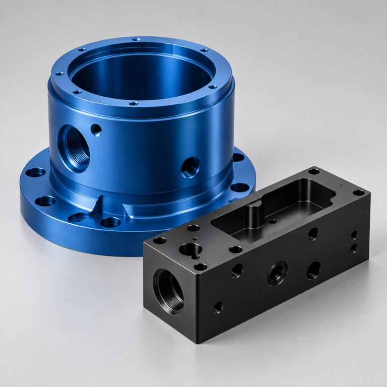
Finishes for your appearance, corrosion and wear requirements.
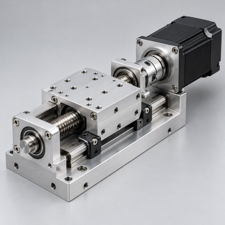
Sub-assemblies and final builds for your production program.
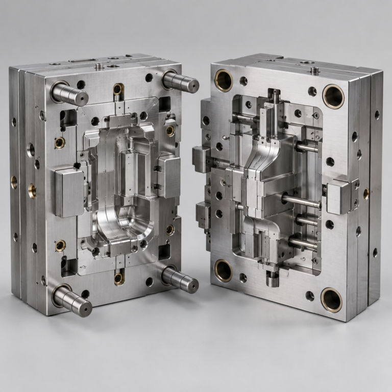
Production tooling built around your process and volume.
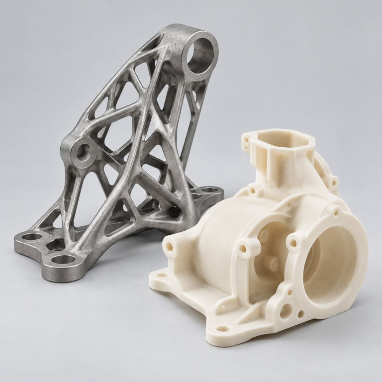
Prototype parts to check fit, function and design.
DFM, process planning and production support for your project.
Inspection, documentation, inventory and delivery planning for your program.
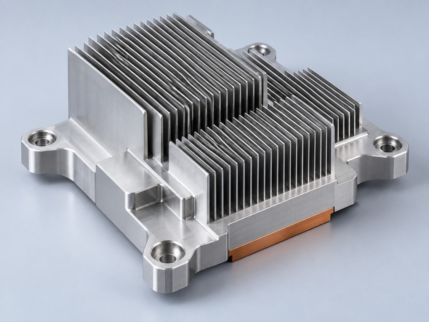
Choose air- or liquid-cooling components around your thermal and mechanical requirements.
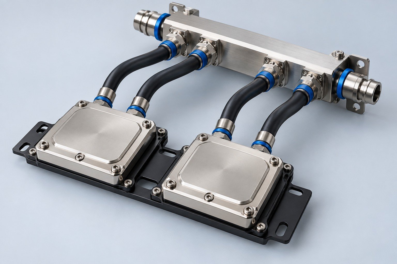
Manufacturing support for your cold plates, manifolds and cooling assemblies.
Find components for your power electronics, energy, laser and telecom application.
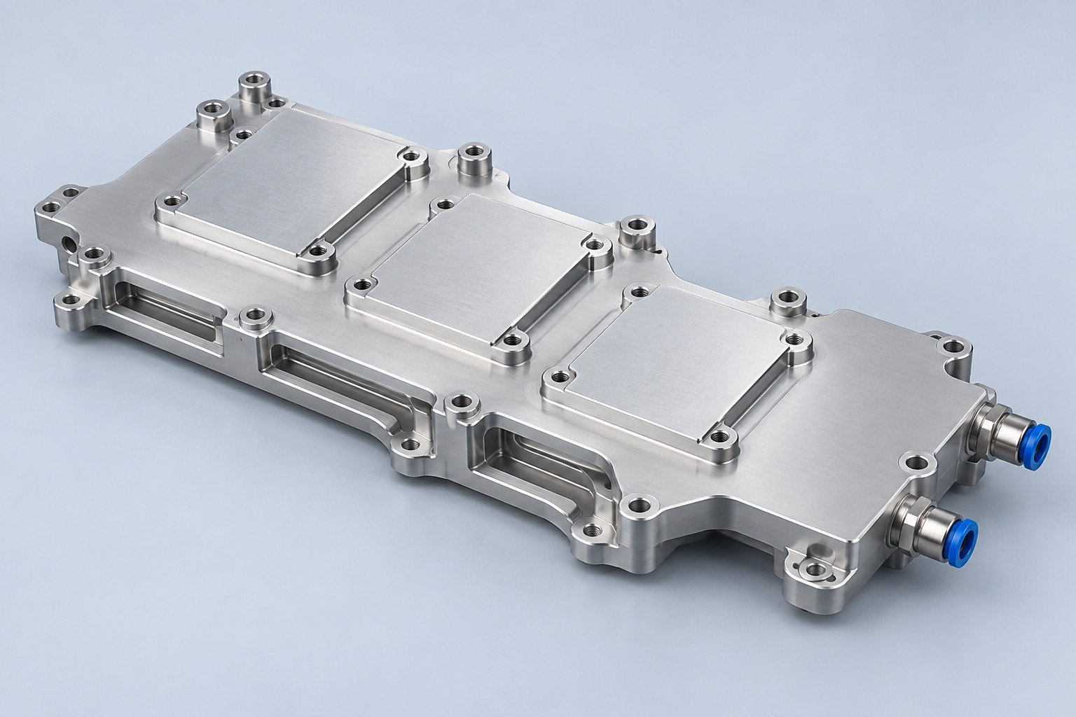
Components for your electronic systems.
Start with your functional and quality requirements.
Build around your operating environment.
From prototype to production, review material performance, manufacturability and cost for your part.
Review grade, temper and finish for your metal parts.
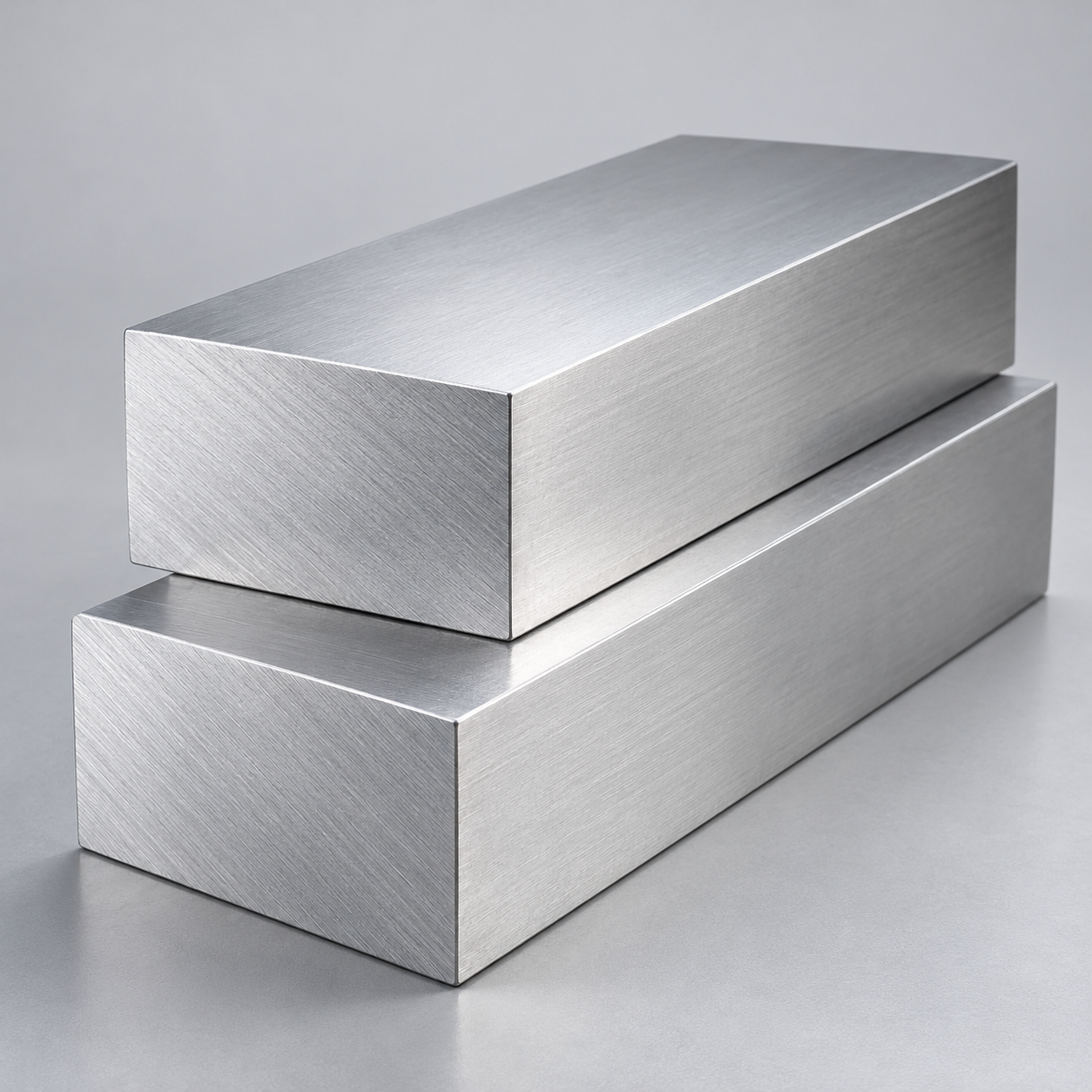 AluminumStrength, weight and machining›
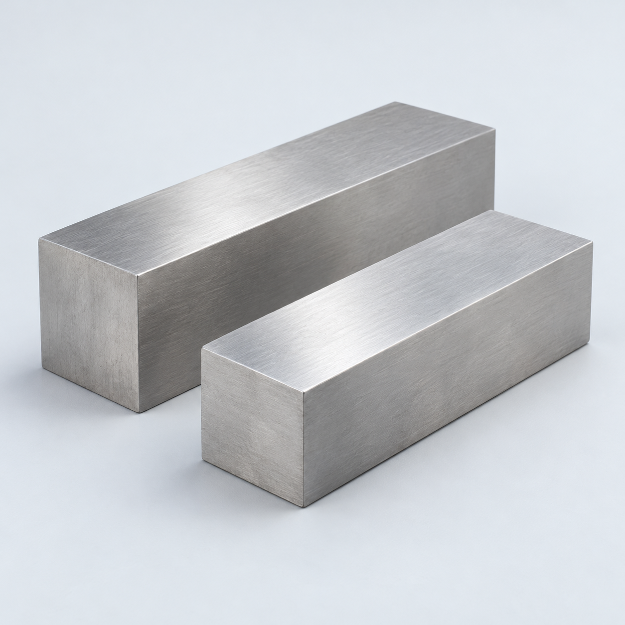 Stainless SteelCorrosion and finish requirements›
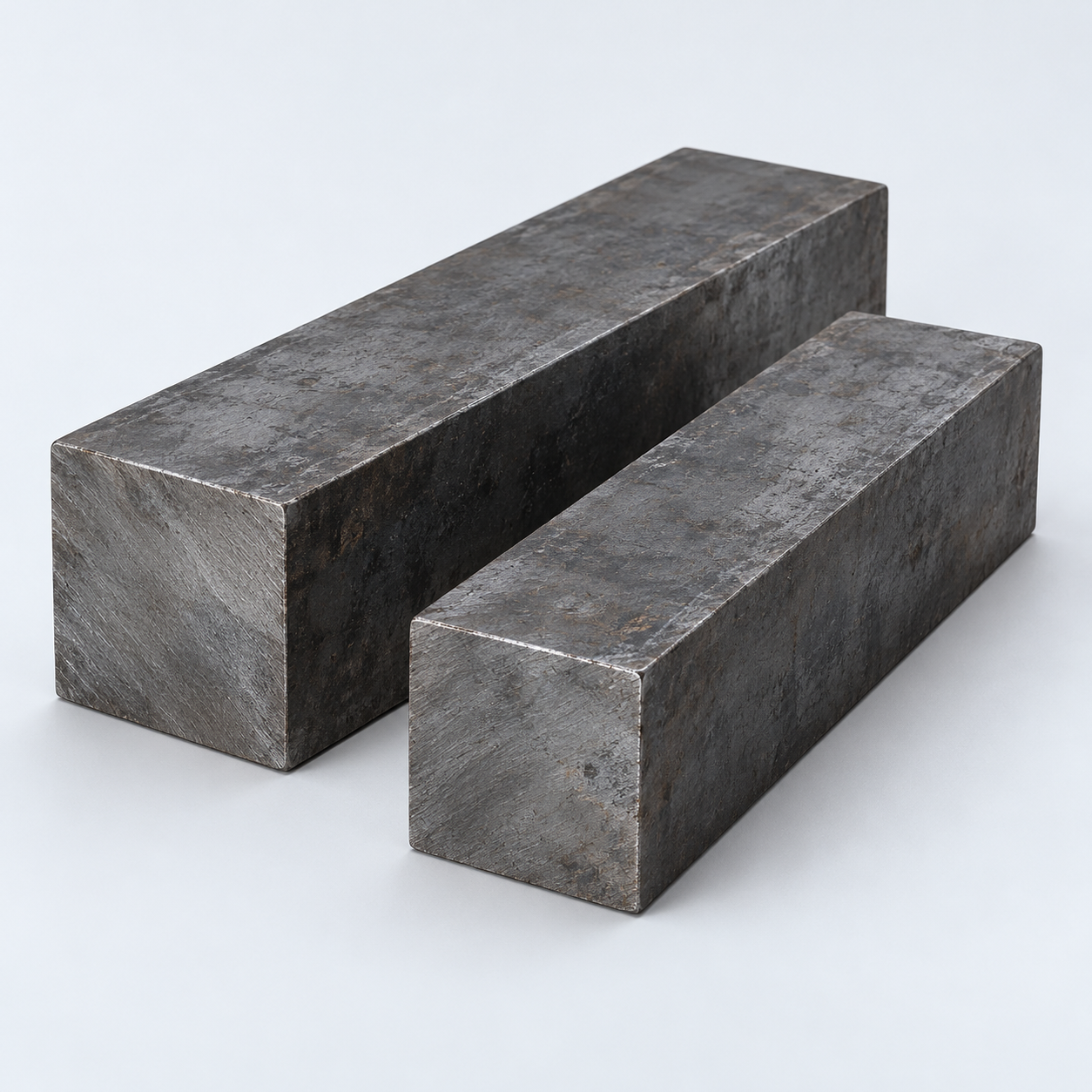 Carbon & Alloy SteelDiscuss grade and heat treatment›
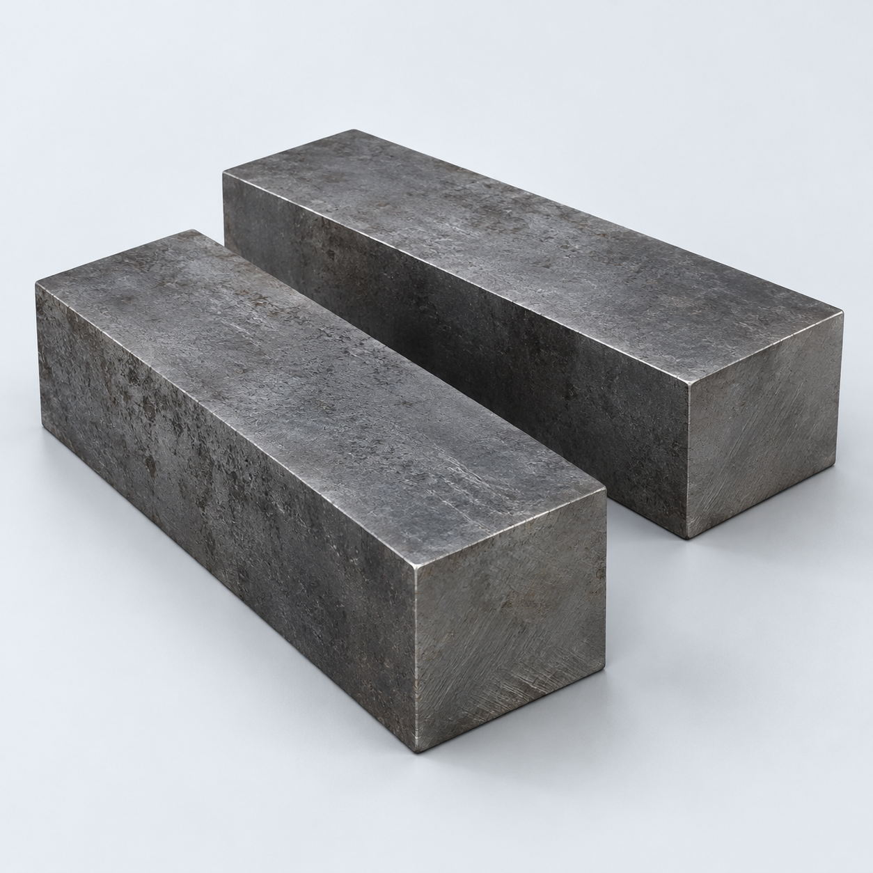 Tool SteelDiscuss tooling and wear needs›
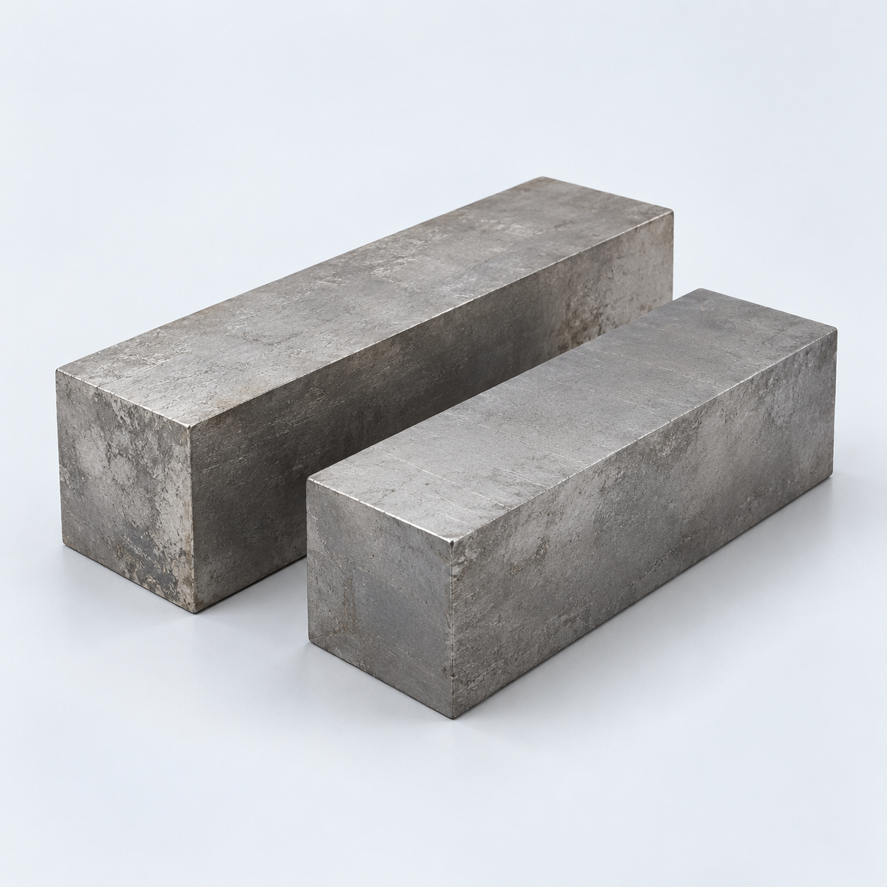 TitaniumReview grade and part geometry›
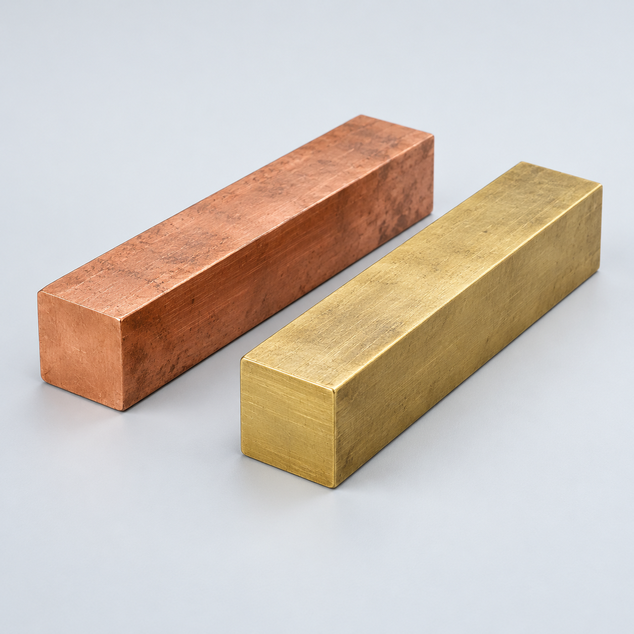 Copper & Brass & BronzeDiscuss conductivity and machining›
Match your polymer to function, process and environment.
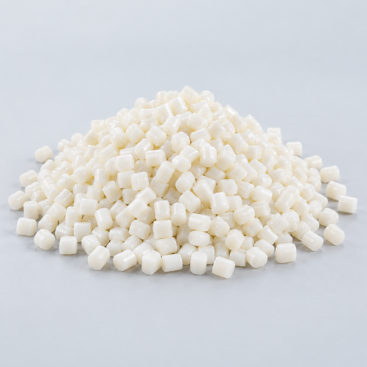 ABSReview enclosure and molding needs›
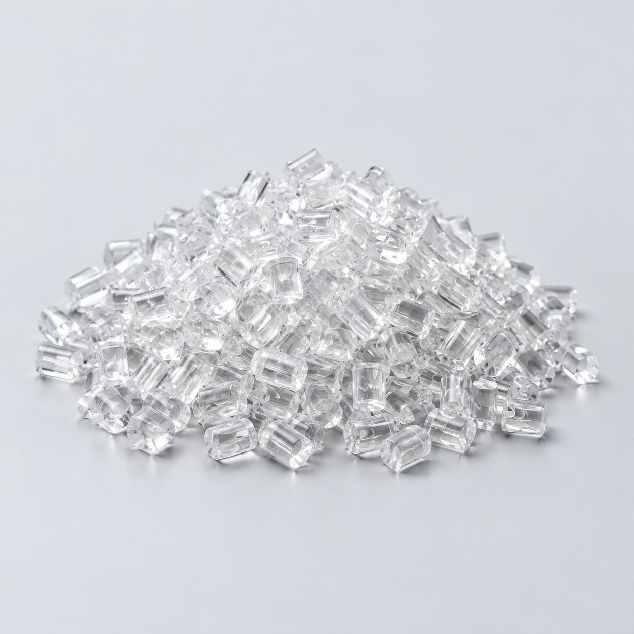 Polycarbonate (PC)Discuss clarity and impact needs›
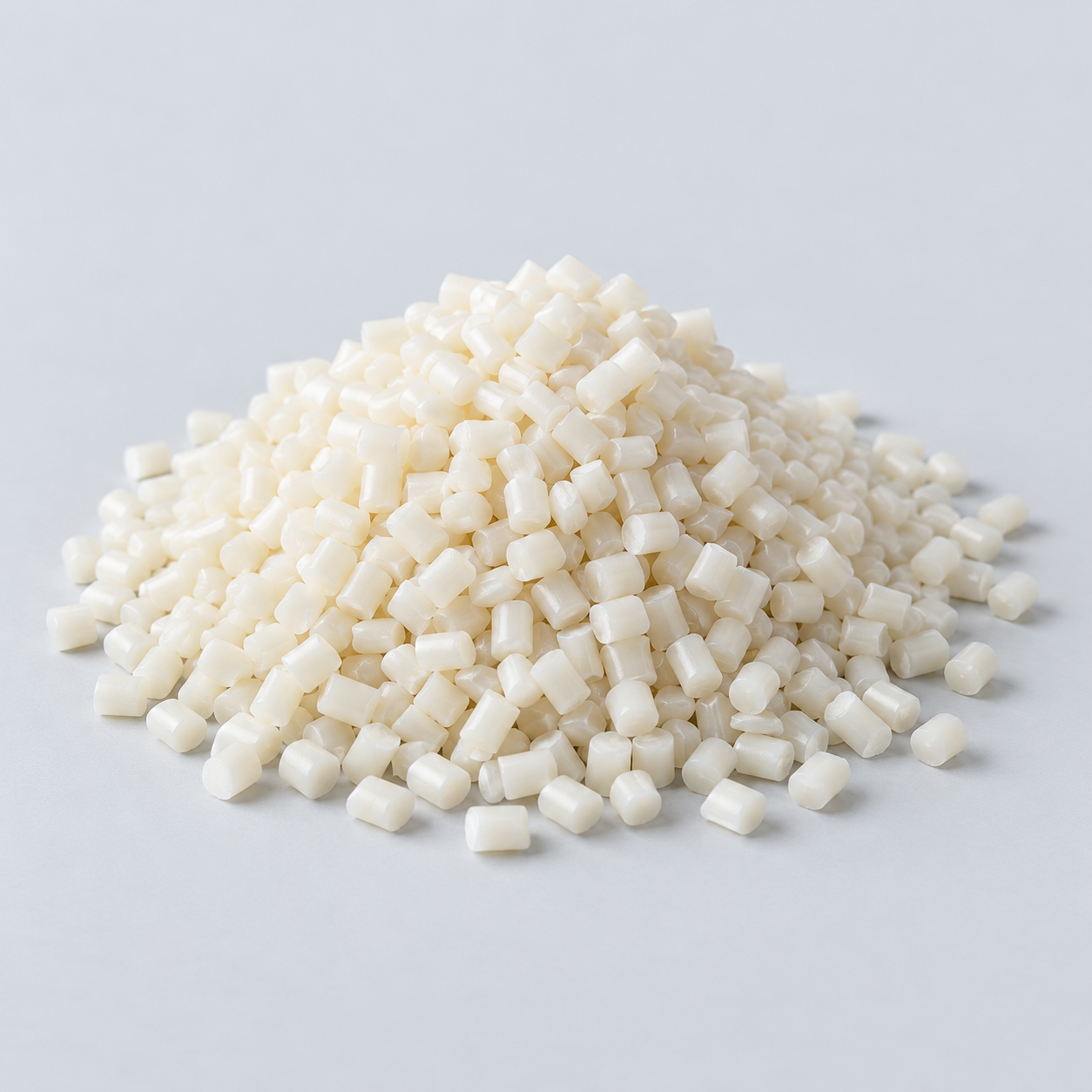 Nylon (PA)Review moisture and wear conditions›
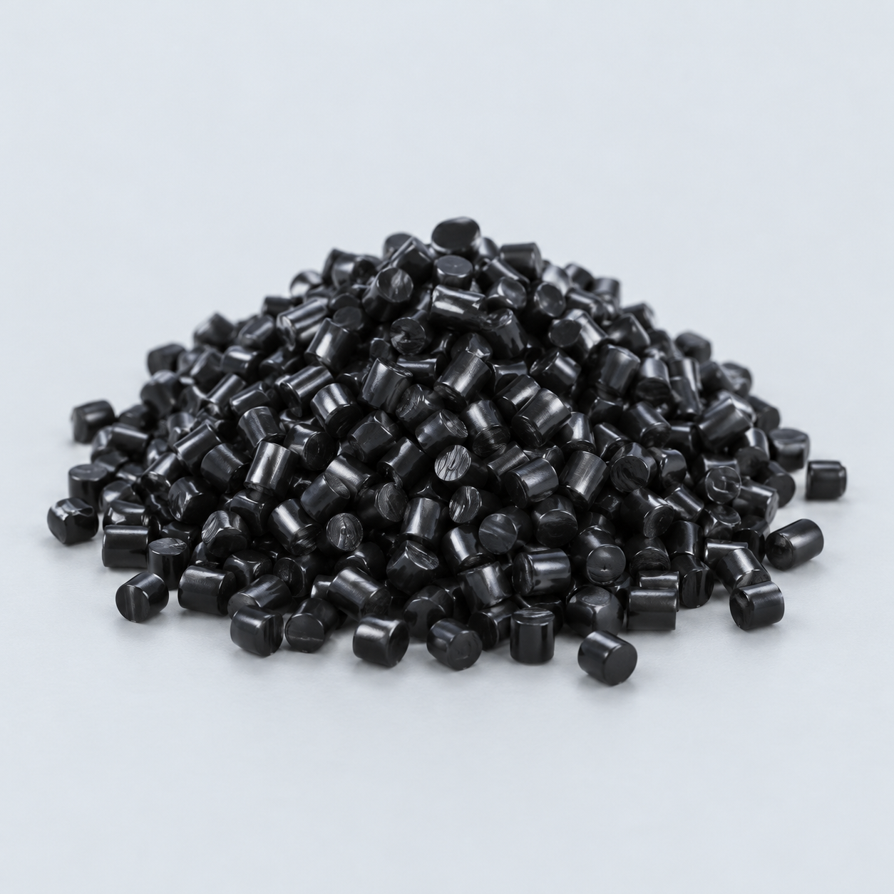 POM / AcetalReview fit and sliding features›
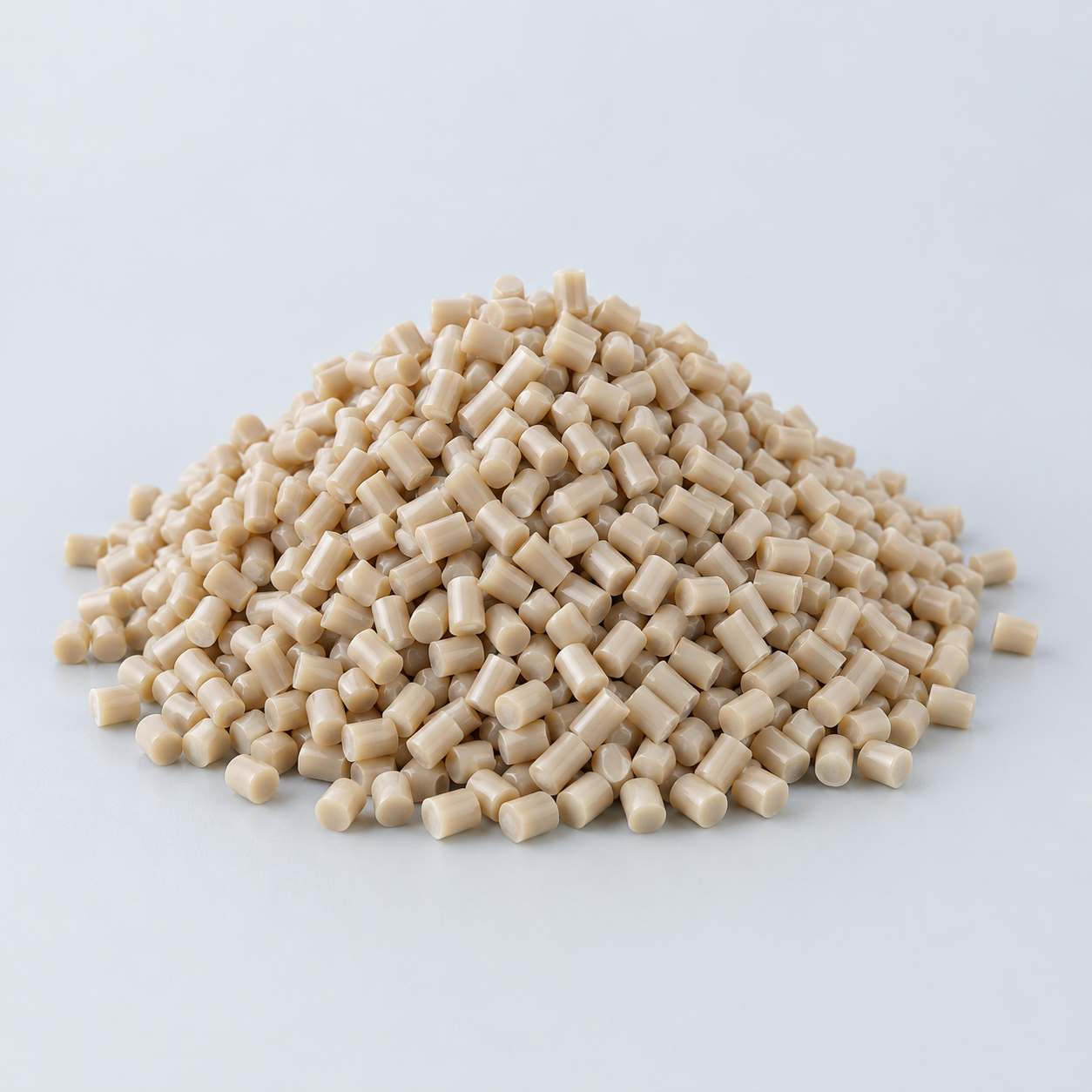 PEEKDiscuss operating conditions›
 PTFEReview friction and chemical exposure›
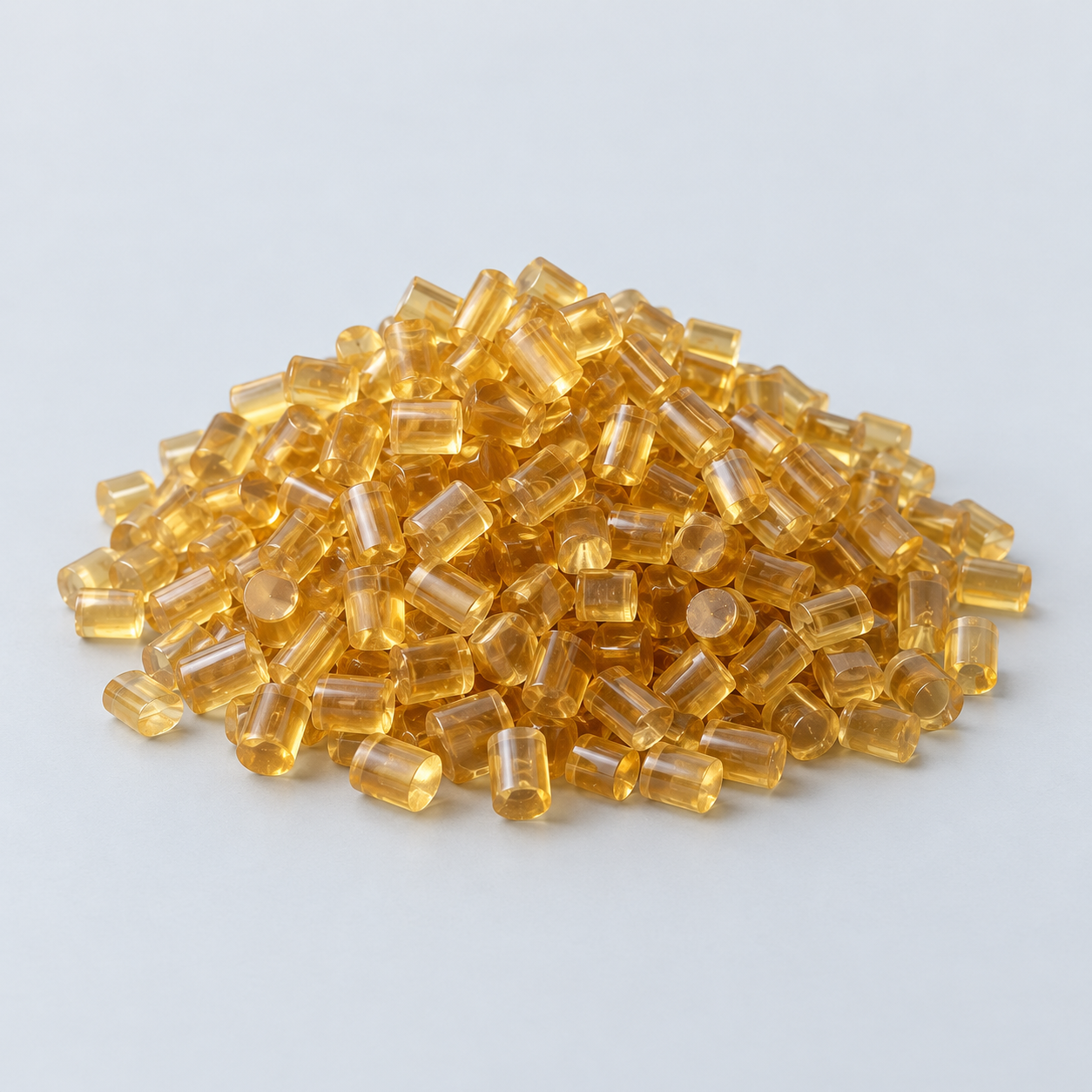 ULTEM / PEIDiscuss thermal and electrical needs›
Confirm grade availability and application requirements.
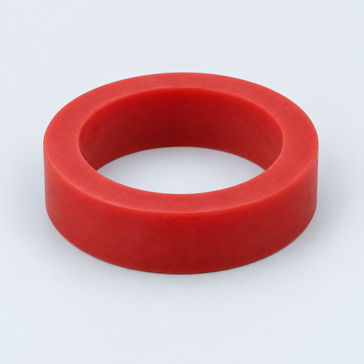 Silicone / LSRDiscuss flexible component needs›
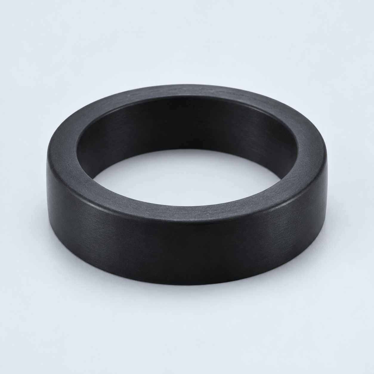 TPU / TPEReview flexibility and processing›
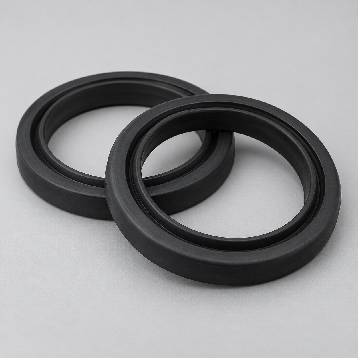 EPDMReview weathering and chemical exposure.›
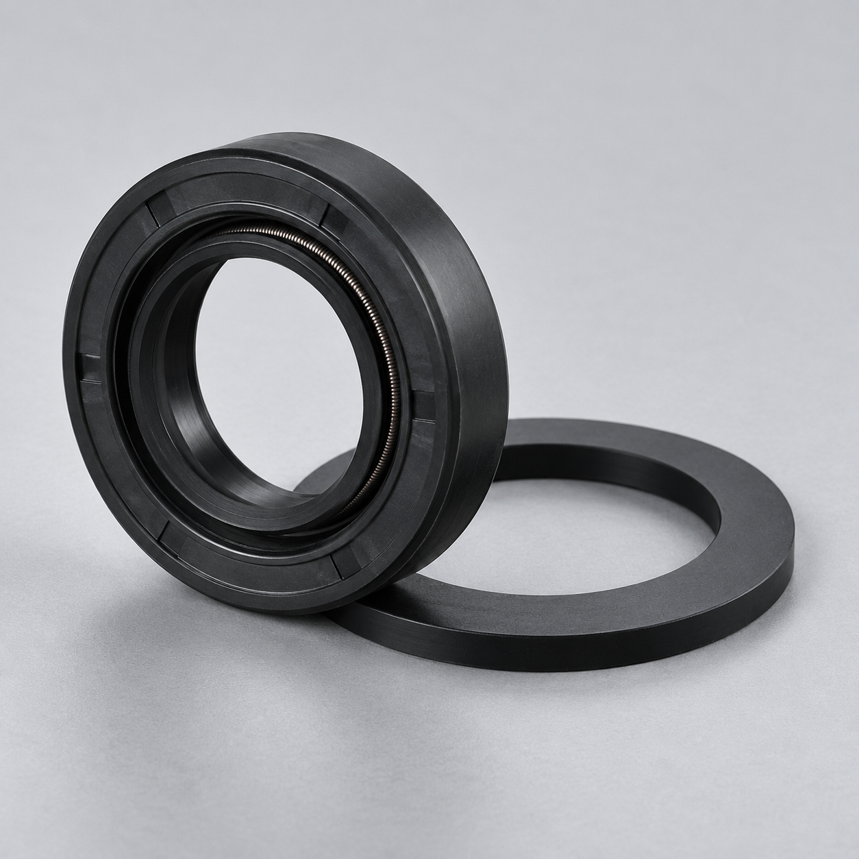 NBRReview oil and fuel exposure.›
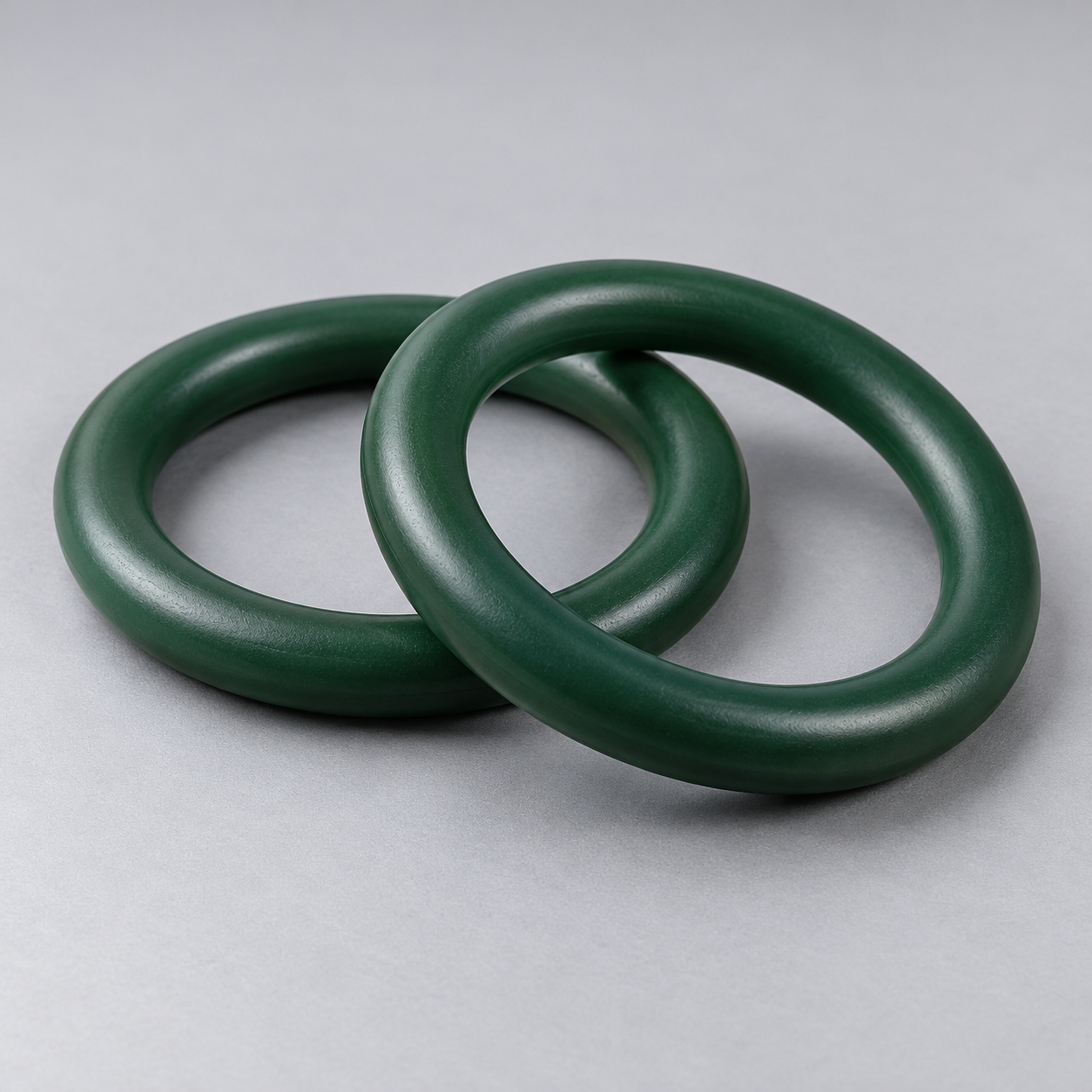 FKMReview temperature and chemical exposure.›
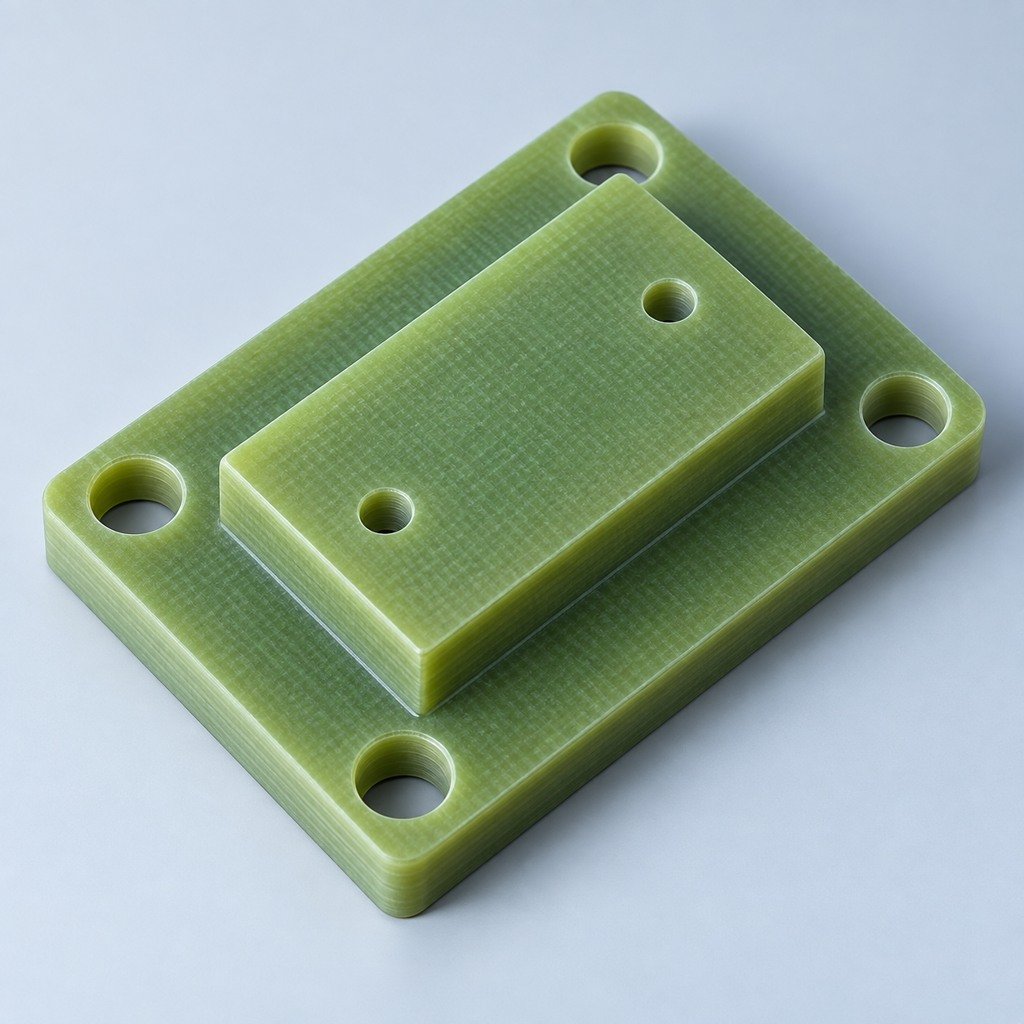 G10 / FR4Review insulation and laminate needs›
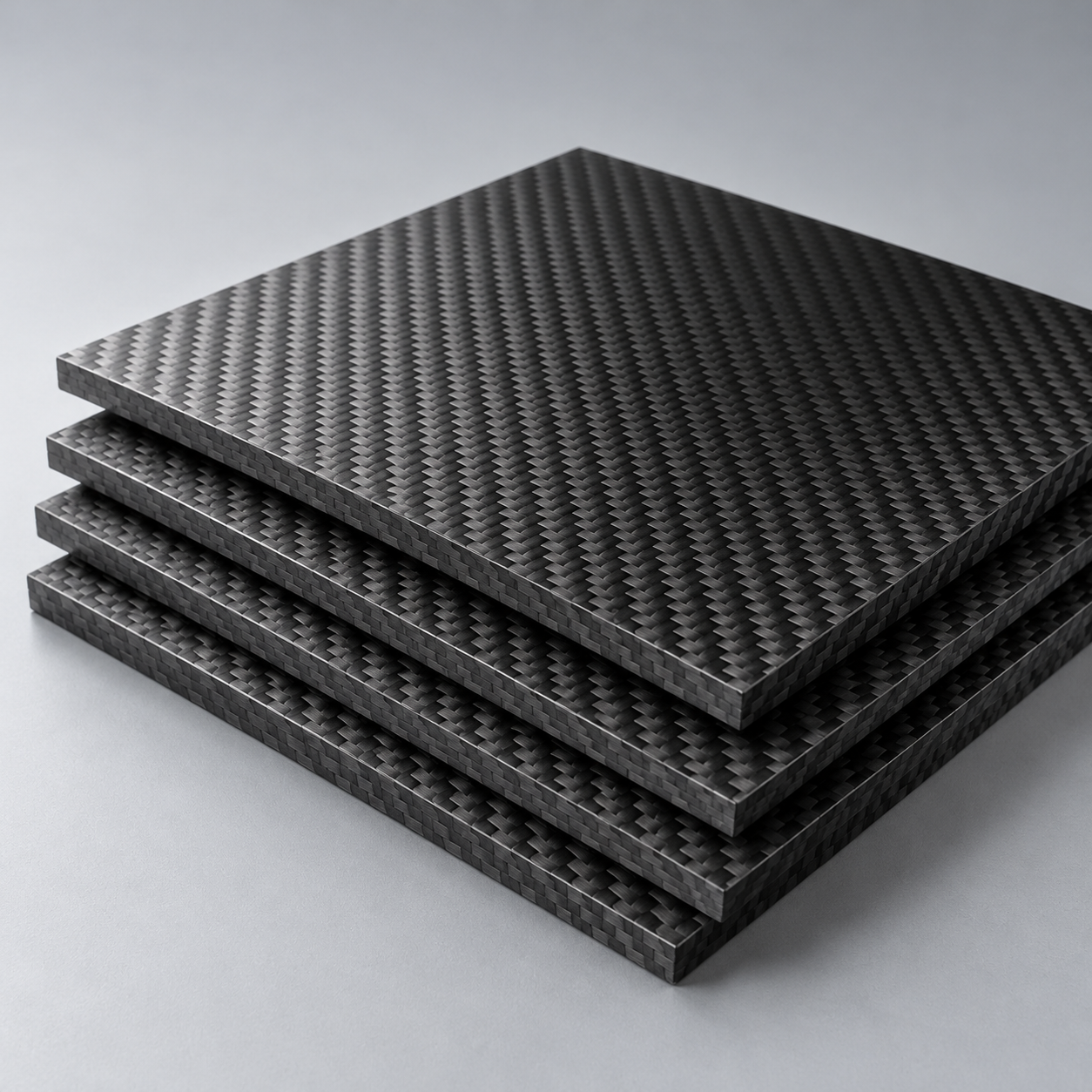 CompositesReview stiffness, weight and laminate.›Customer-Specified MaterialsConfirm your grade and requirements.›Other Specialty MaterialsDiscuss your application and grade.›
Practical guidance for your part geometry and material decisions.
Prepare your process, budget and sourcing questions.
Build your knowledge before production.
Learn who we are and how we operate.
Find our U.S. support team or start a conversation.

YOUR APPLICATION. YOUR ENCLOSURE. YOUR INSTALLED FIT.
Choose the application closest to your part, then define its mechanical interfaces. Your enclosure, mounting hardware and equipment supports need a controlled drawing, material condition and clear acceptance scope before the manufacturing route is agreed.
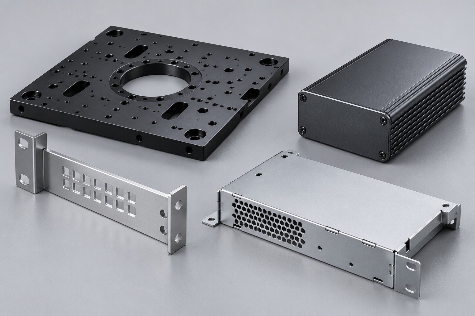
Use the semiconductor route for custom semiconductor equipment components with defined locating features and documented handling requirements.
Explore this application →Review custom server mounting brackets against chassis holes, rack interfaces and service access; connect thermal components to a separate cooling review.
Explore this application →Connect appearance zones, connector openings and final assembled fit before choosing tooling or surface treatment.
Explore this application →For aluminum housings for networking equipment, first identify the installed environment, cable access and mating seals.
Explore this application →A connector opening that fits on the bench may conflict with a cable, fastener or neighboring panel after assembly. Review the installed condition, not only the isolated component.
Identify datum faces, fastener patterns, standoffs and assembly clearances.
Mark masked areas, grounding interfaces where specified and surfaces checked after finishing.
Define cosmetic finishing for electronics enclosures through appearance zones, an approved sample and protected contacts.

This fixed-volume calculation compares material density, not finished-enclosure weight, shielding, strength or thermal performance. The assumed material volume is 10 cm³ in every case.
Mass = density × volume. Zero baseline 0–90 g.
Selected reference densities:6061≈2.7g/cm³ (Hydro0.098lb/in³,converted and rounded);316L8.0g/cm³ at20°C;Cu-ETP8.92g/cm³,annealed at20°C. Use your actual CAD volume and specified product form for a part estimate.
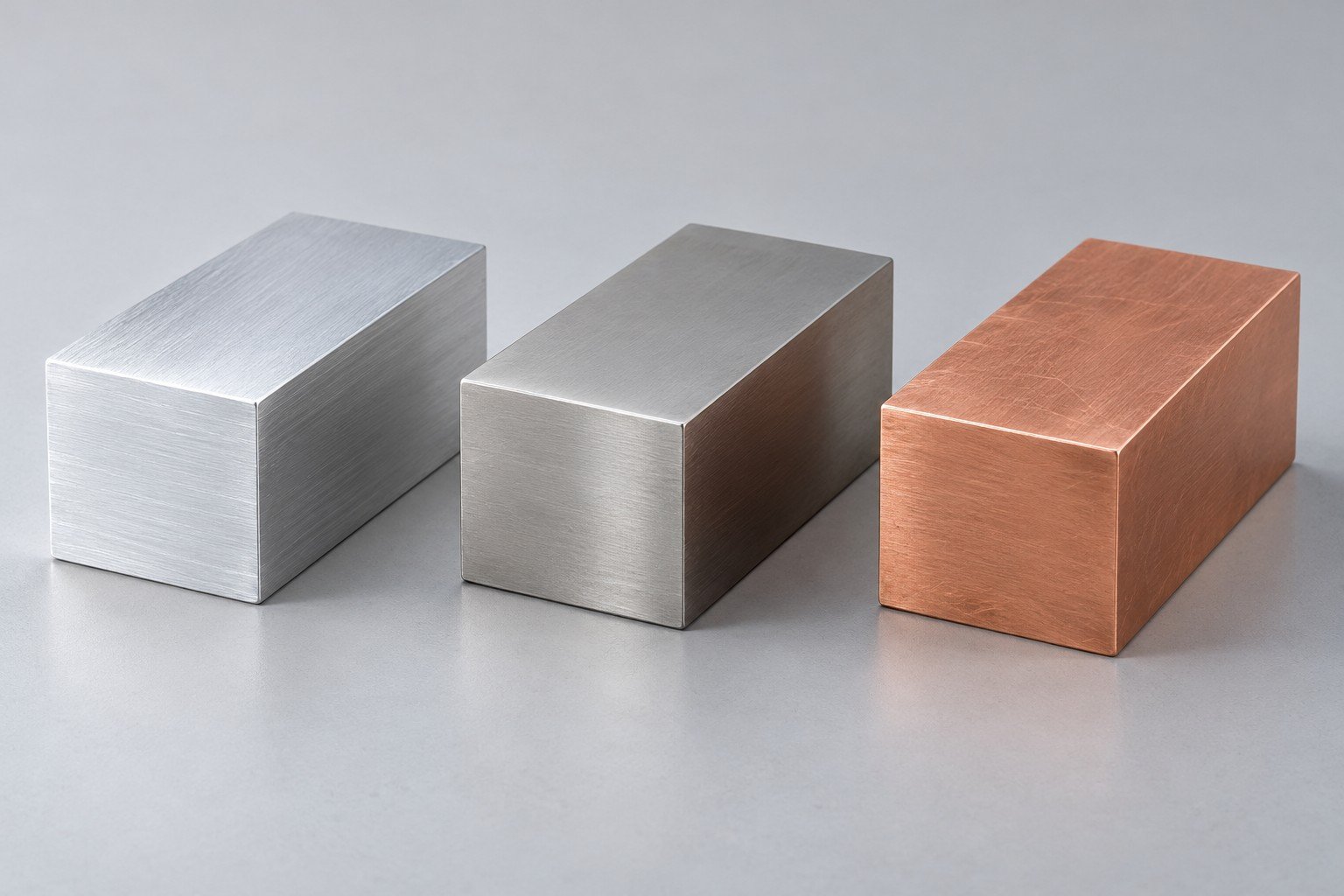
Check geometry, stiffness, contact function, finish and required evidence together. Equal volume does not mean equal performance.
| Reference grade | European reference | Confirm for your order |
|---|---|---|
| 6061 | EN AW-6061 | Temper, product form, full purchasing specification |
| 316L | 1.4404 / X2CrNiMo17-12-2 | Governing grade standard and condition |
| C11000 | Cu-ETP / CW004A | Product form and required material certificate |
Reference names are not automatic substitution approval. Density values and source conditions are material references,not batch test results. Hydro6061 → · thyssenkrupp316L → · KME Cu-ETP →
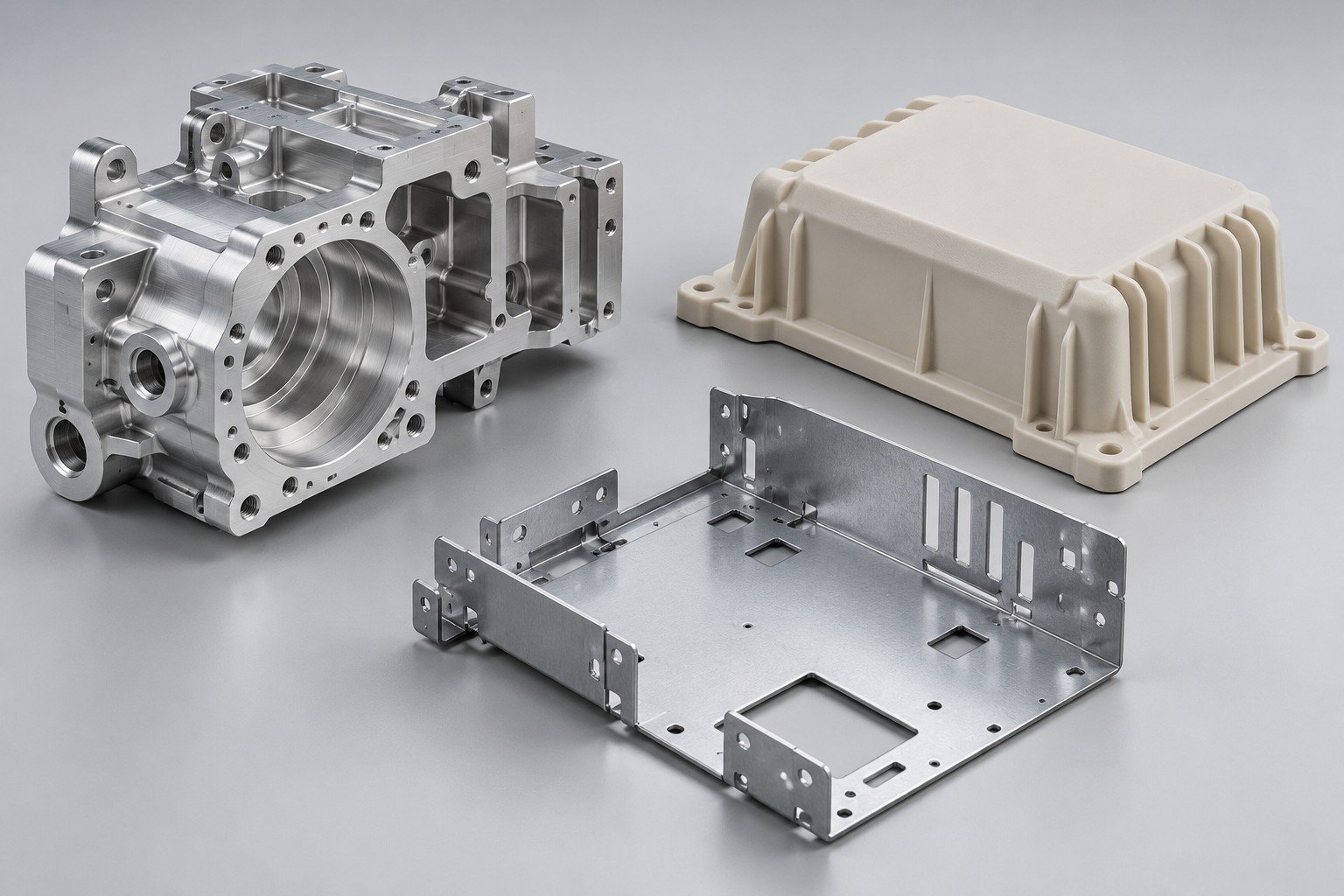
Use the machining review for precise locating faces, pockets, bores and selected final-condition checks. Explore CNC machining →
Review bends, panel openings, rack ears, hardware and assembled clearances together. Explore sheet metal →
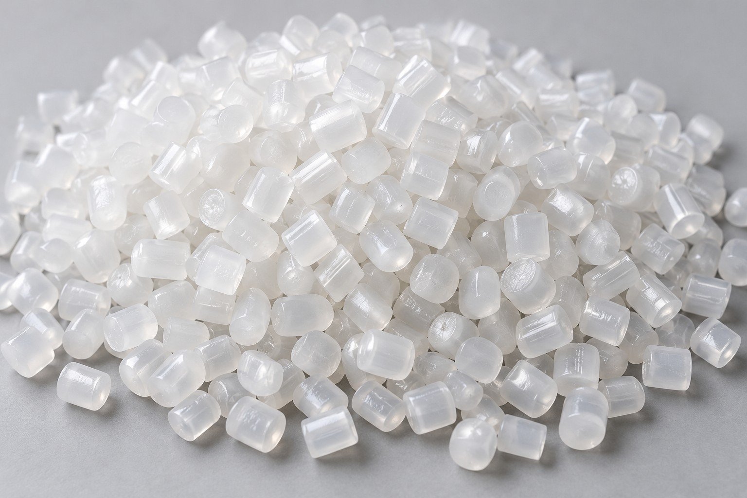
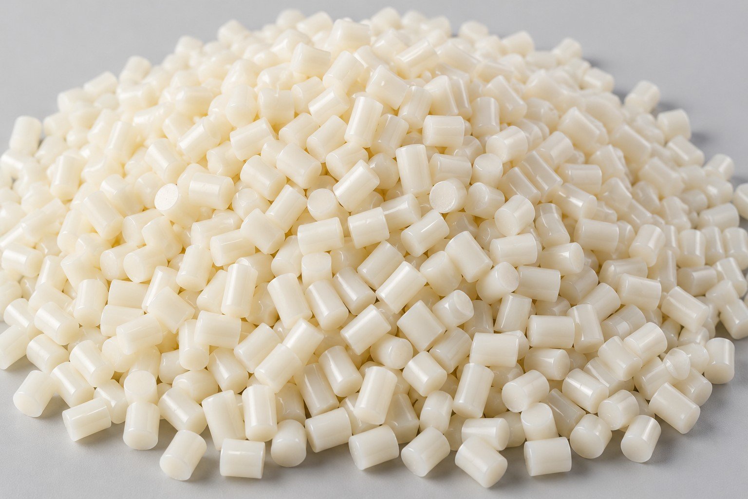
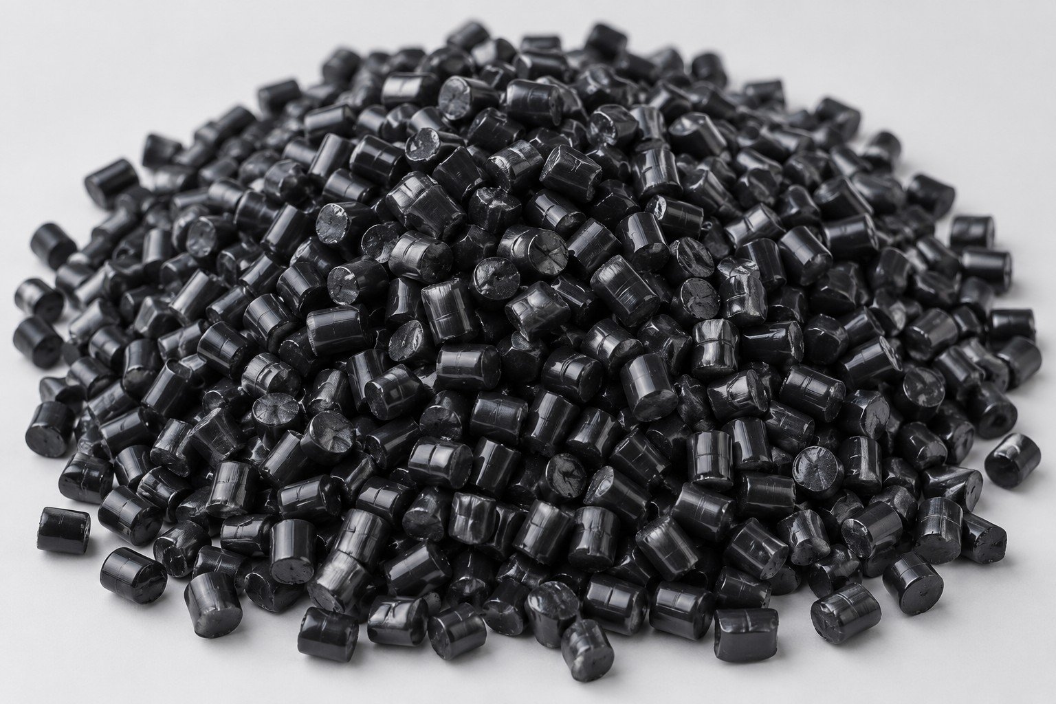
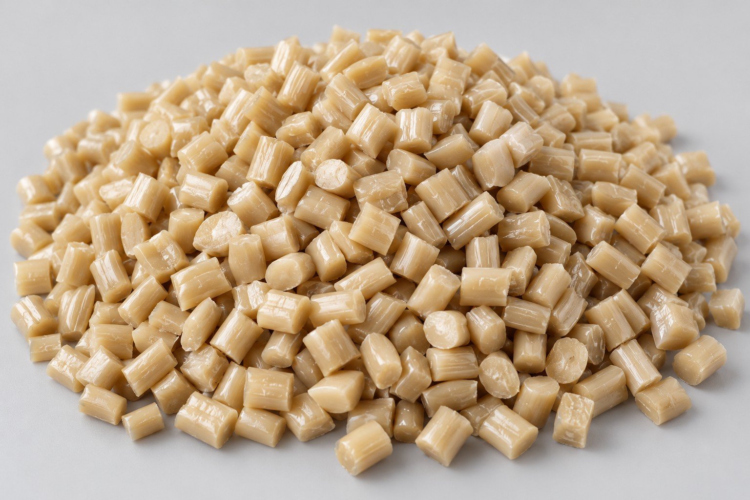
Discuss resin, draft, ribs, appearance and the expected revision cycle before tooling. Explore molding →
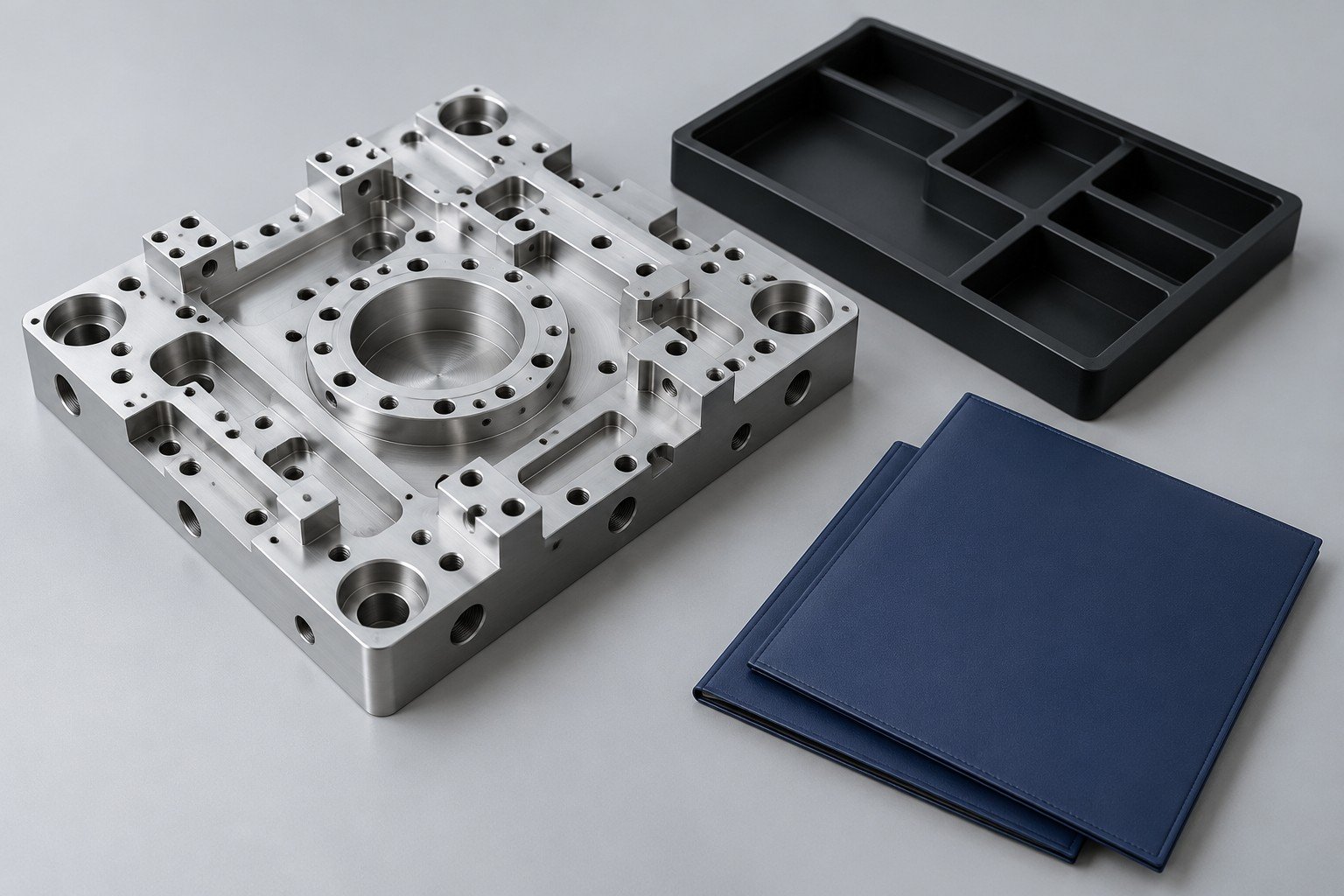
Start with the records that answer your purchasing and assembly questions. Dimensional acceptance of a housing does not establish electrical, EMC, ingress or complete-system compliance.
Connect the released revision to the specified grade, condition and requested material records.
Identify the mounting, connector and contact features checked after finishing.
Define cleaning, cosmetic protection, packaging and the responsible approval contact.
Choose the relevant industry path and describe installed function.
Resolve mating, mounting, appearance and access requirements.
Agree the revision, material, selected checks and separate system tests.
Confirm approved changes, quantities and protective packing.
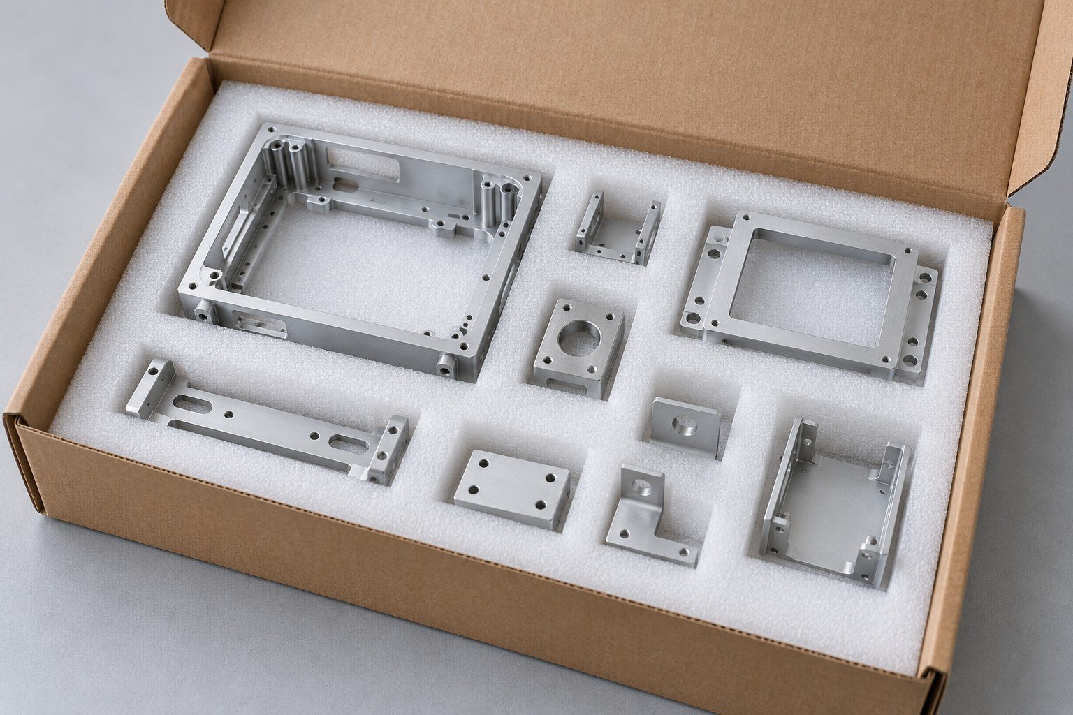

Choose the closest installed application. If the component spans several systems, share its function, mating interfaces and required acceptance records so the scope can be reviewed together.
No. It identifies the material within its stated scope. Electrical, EMC and system-level tests require their own defined method, conditions and approval responsibility.
Mark visible faces, define the color or appearance reference, identify protected contacts and agree how the sample will be accepted before production.
It may,if the differences are agreed. Record which geometry, material or finish differences affect what the prototype can prove before approving repeat production.