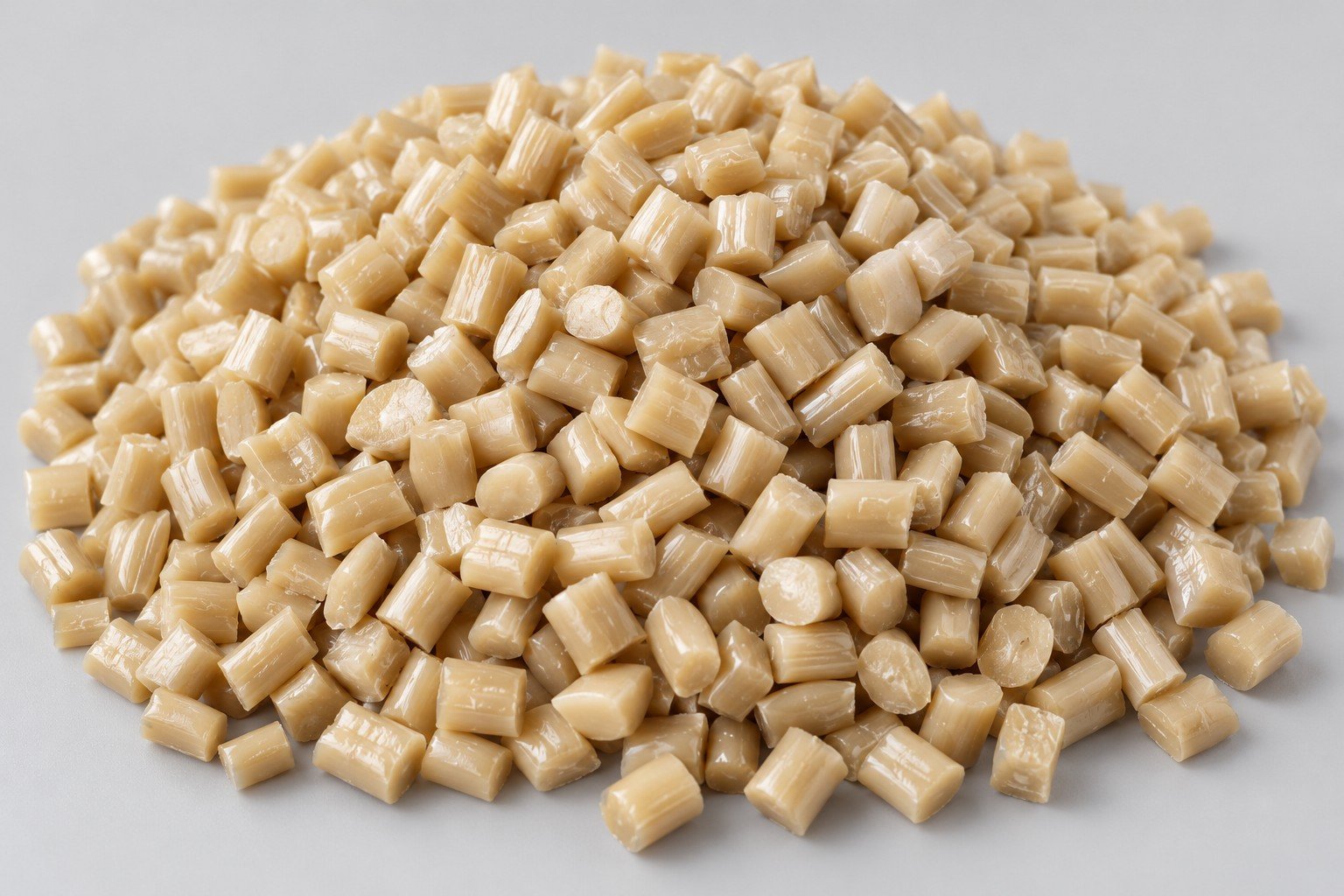
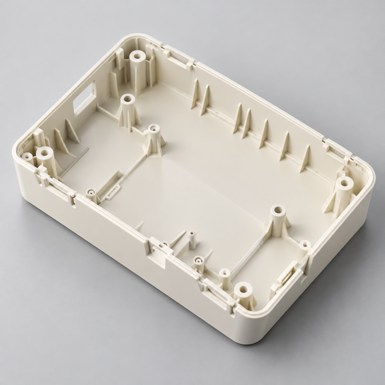
Injection Molding
Tooling and molding for your repeat plastic parts.
From prototype to production, coordinated manufacturing solutions for your custom parts.
View All Services →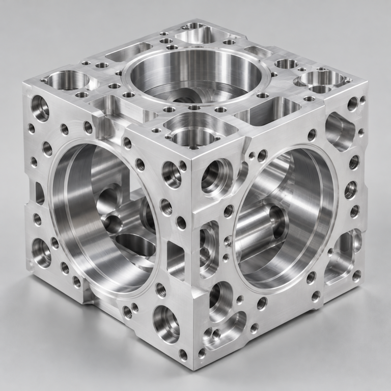
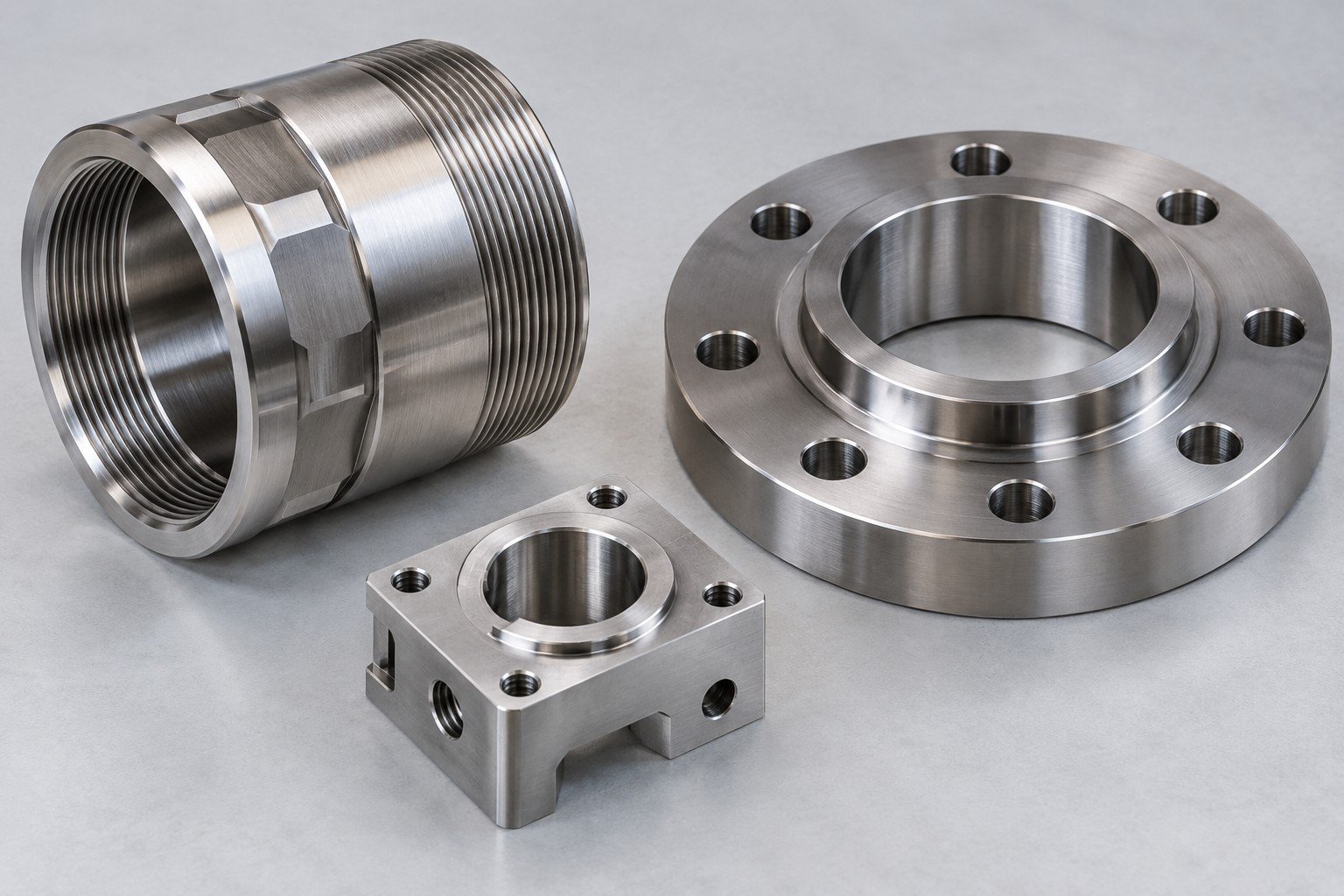
Precision parts for your tight tolerances and complex geometry.
Tooling and molding for your repeat plastic parts.
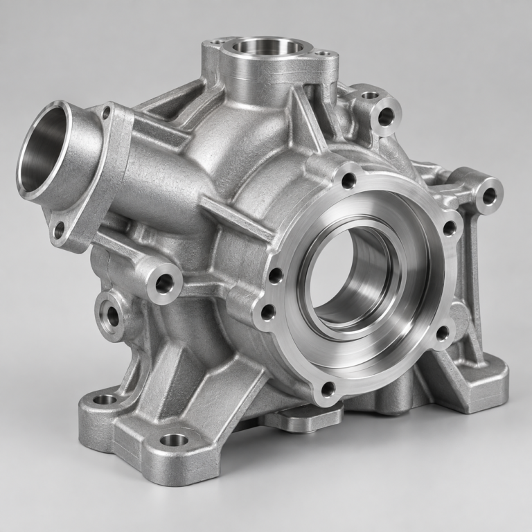
Metal casting options for your part and production volume.
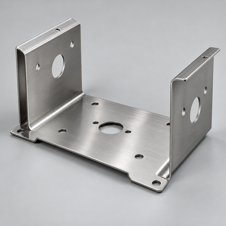
Cutting, forming and welding for your fabricated parts.
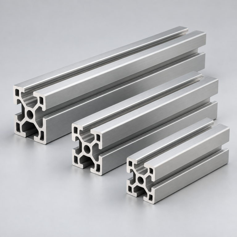
Custom profiles for your section, length and finish requirements.
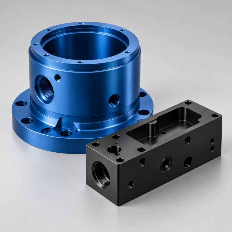
Finishes for your appearance, corrosion and wear requirements.
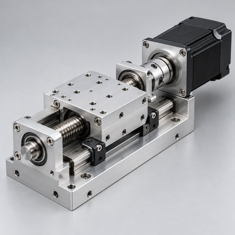
Sub-assemblies and final builds for your production program.
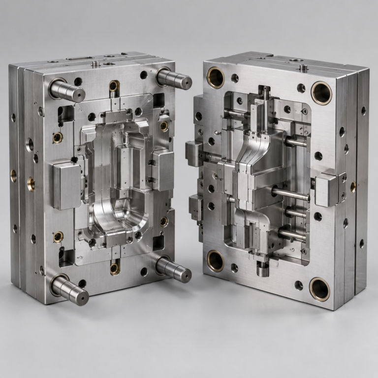
Production tooling built around your process and volume.
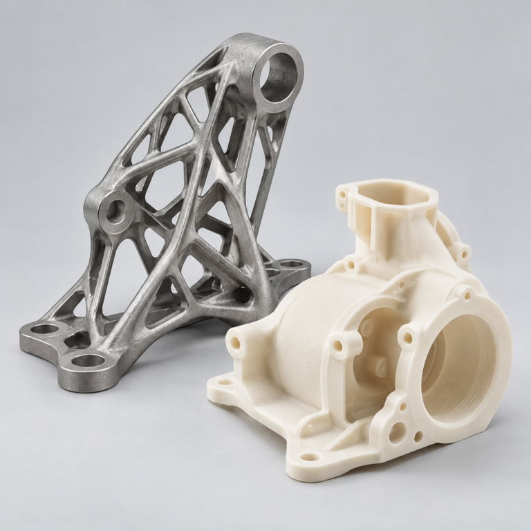
Prototype parts to check fit, function and design.
DFM, process planning and production support for your project.
Inspection, documentation, inventory and delivery planning for your program.
Choose air- or liquid-cooling components around your thermal and mechanical requirements.
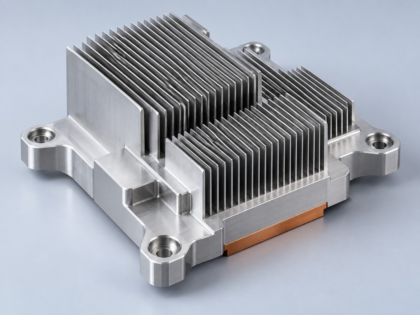
Manufacturing support for your cold plates, manifolds and cooling assemblies.
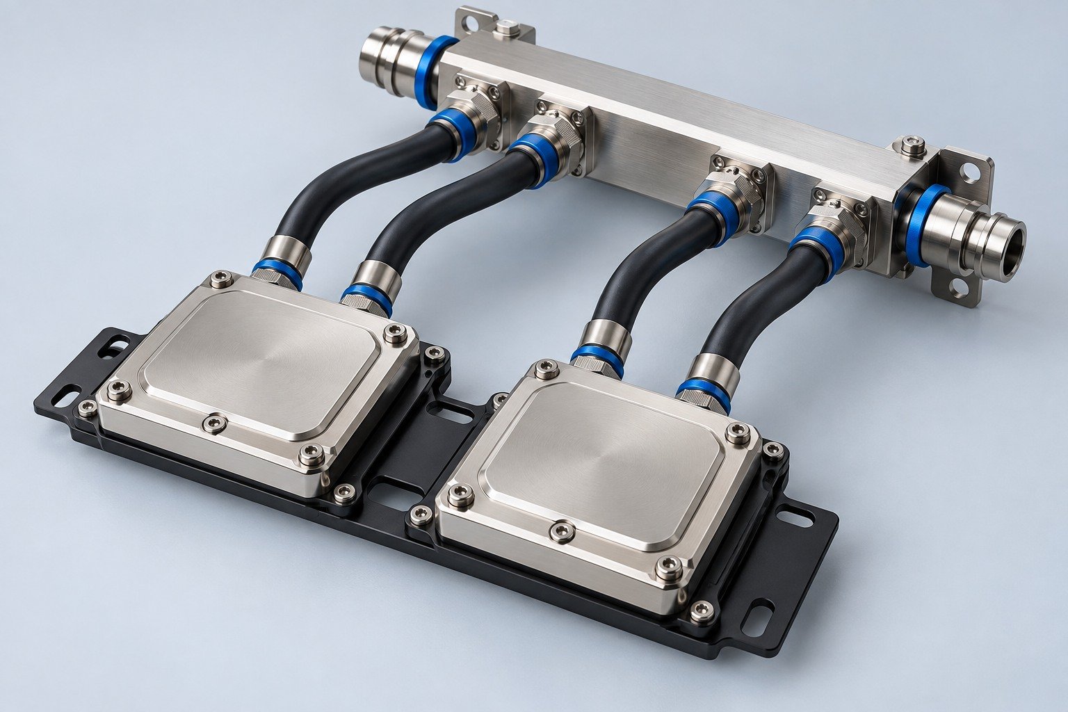
Find components for your power electronics, energy, laser and telecom application.
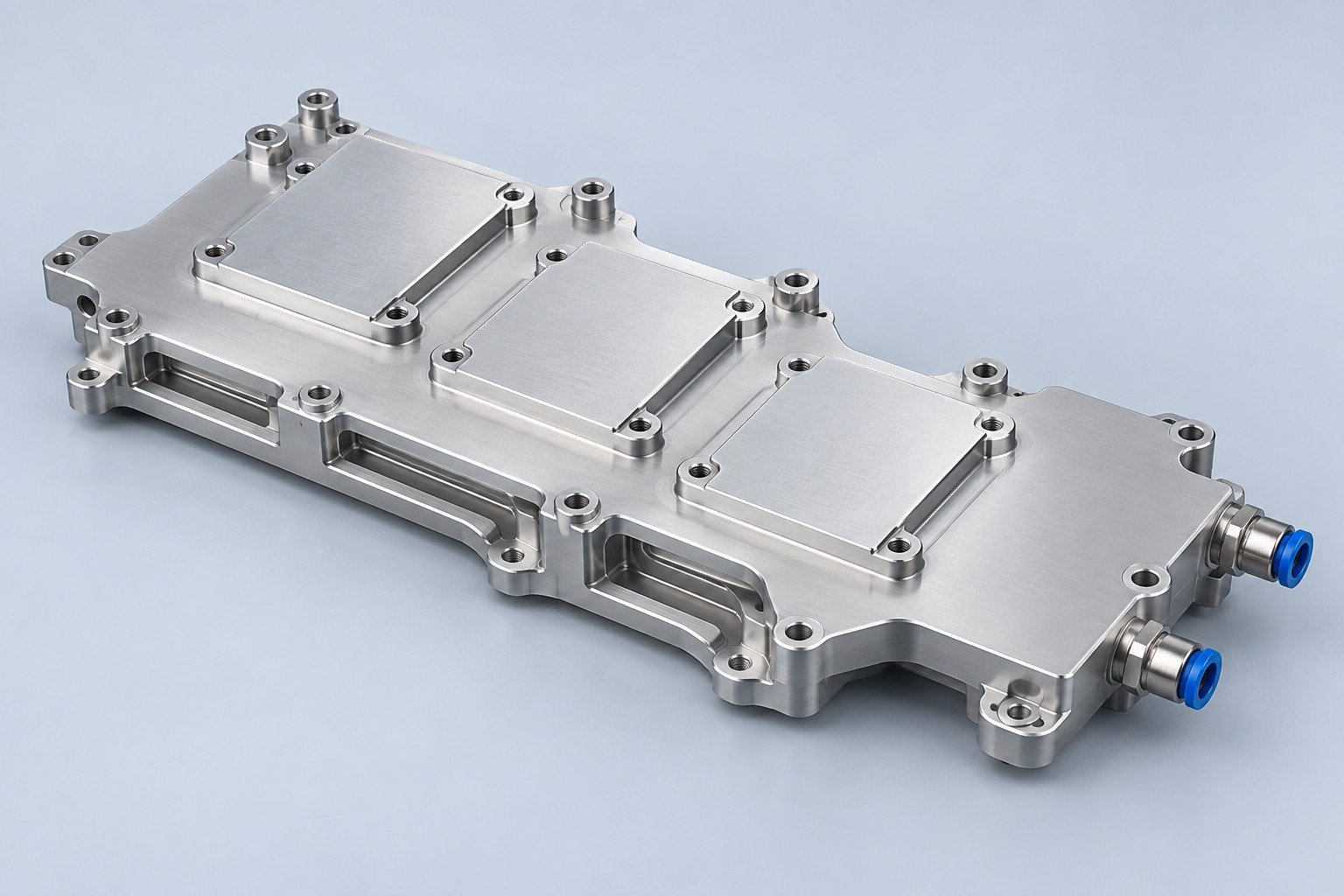
Components for your electronic systems.
Start with your functional and quality requirements.
Build around your operating environment.
From prototype to production, review material performance, manufacturability and cost for your part.
Review grade, temper and finish for your metal parts.
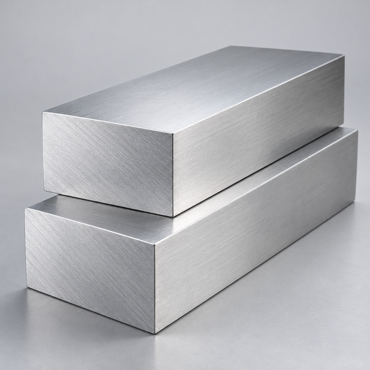 AluminumStrength, weight and machining›
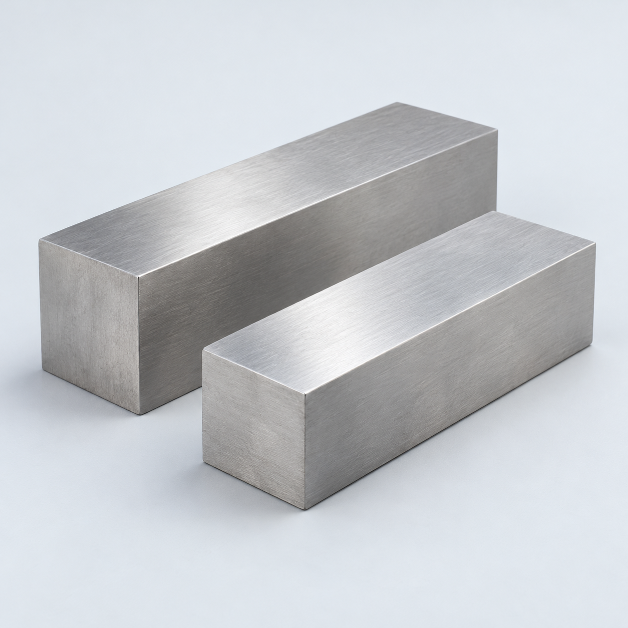 Stainless SteelCorrosion and finish requirements›
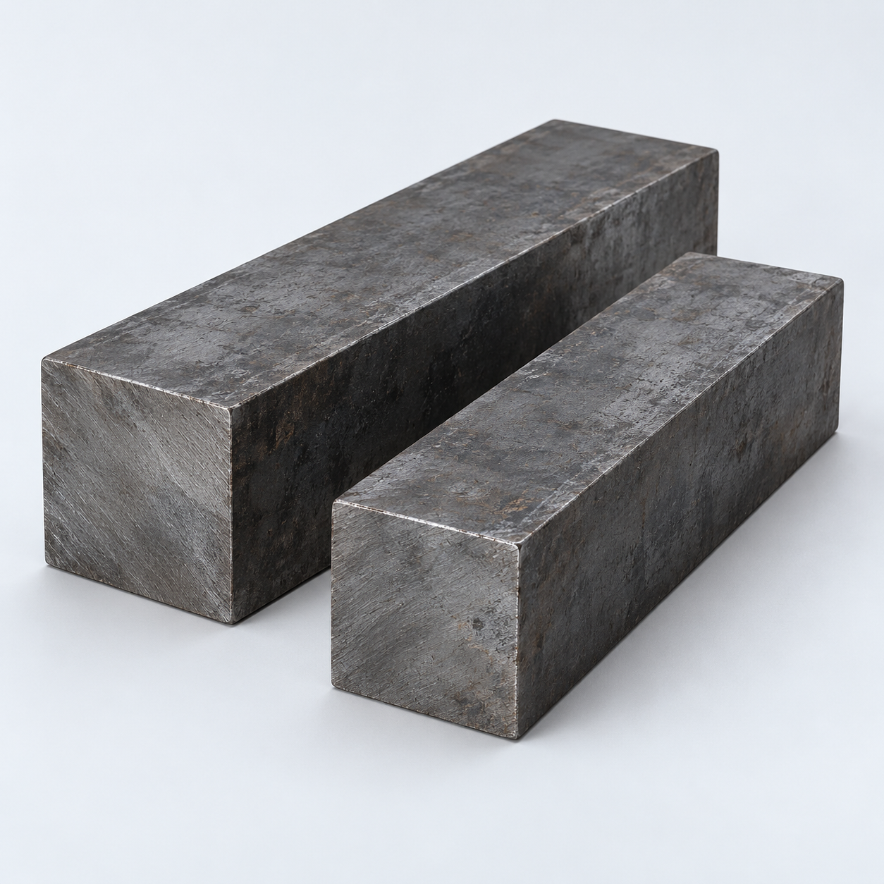 Carbon & Alloy SteelDiscuss grade and heat treatment›
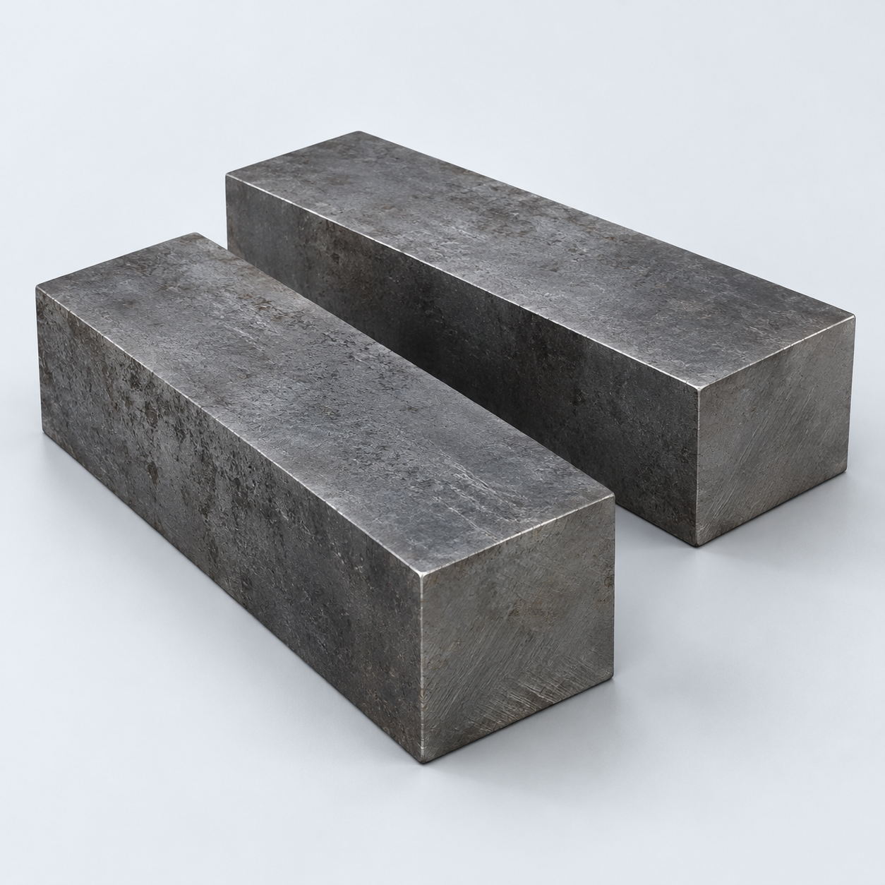 Tool SteelDiscuss tooling and wear needs›
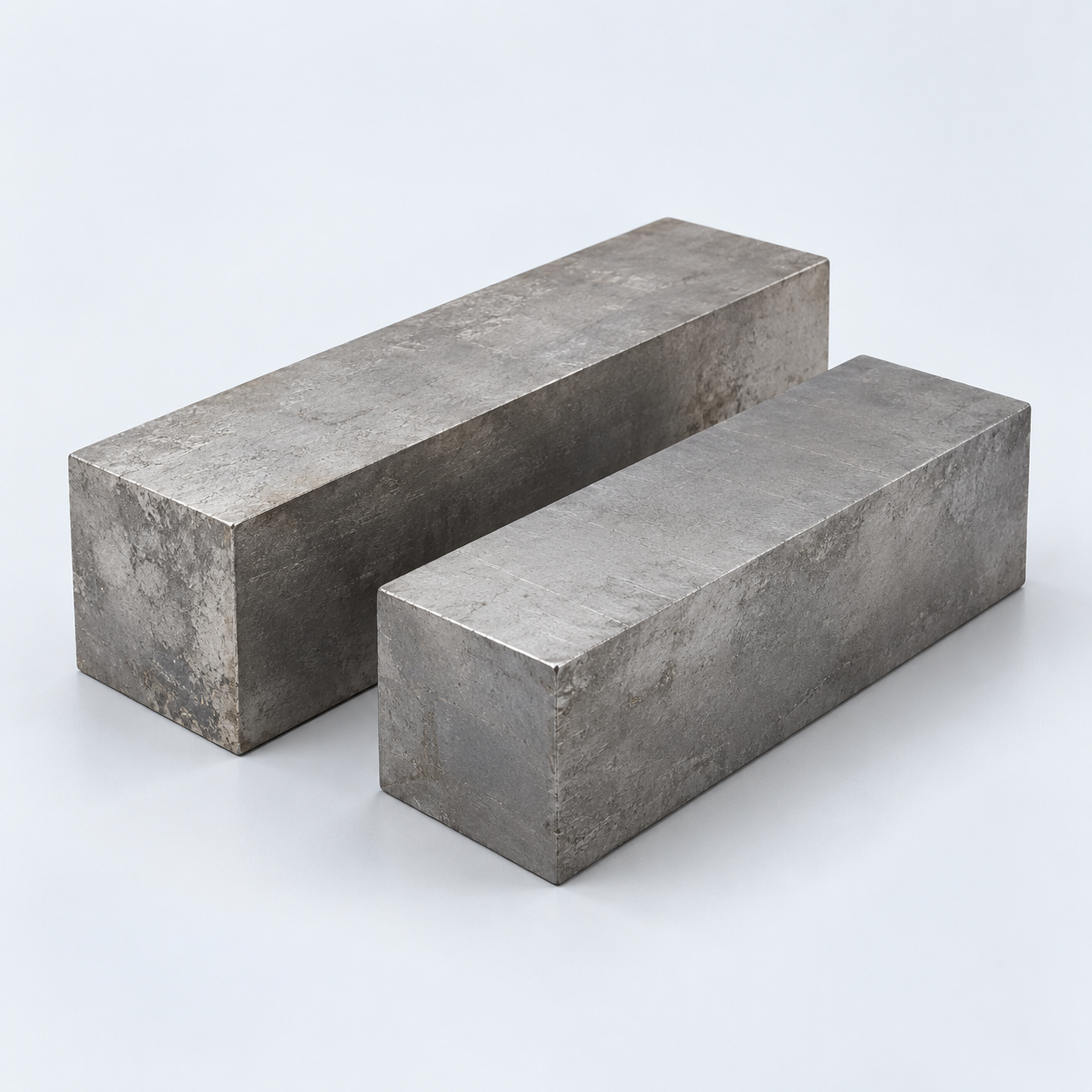 TitaniumReview grade and part geometry›
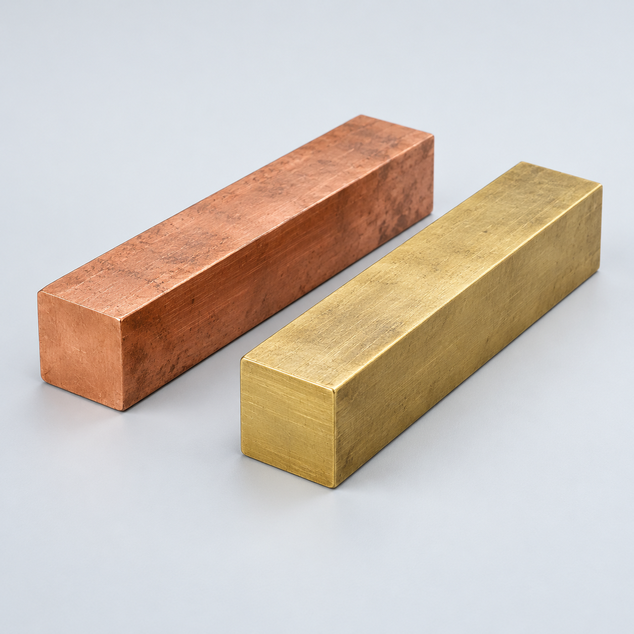 Copper & Brass & BronzeDiscuss conductivity and machining›
Match your polymer to function, process and environment.
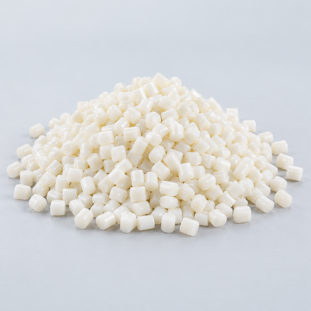 ABSReview enclosure and molding needs›
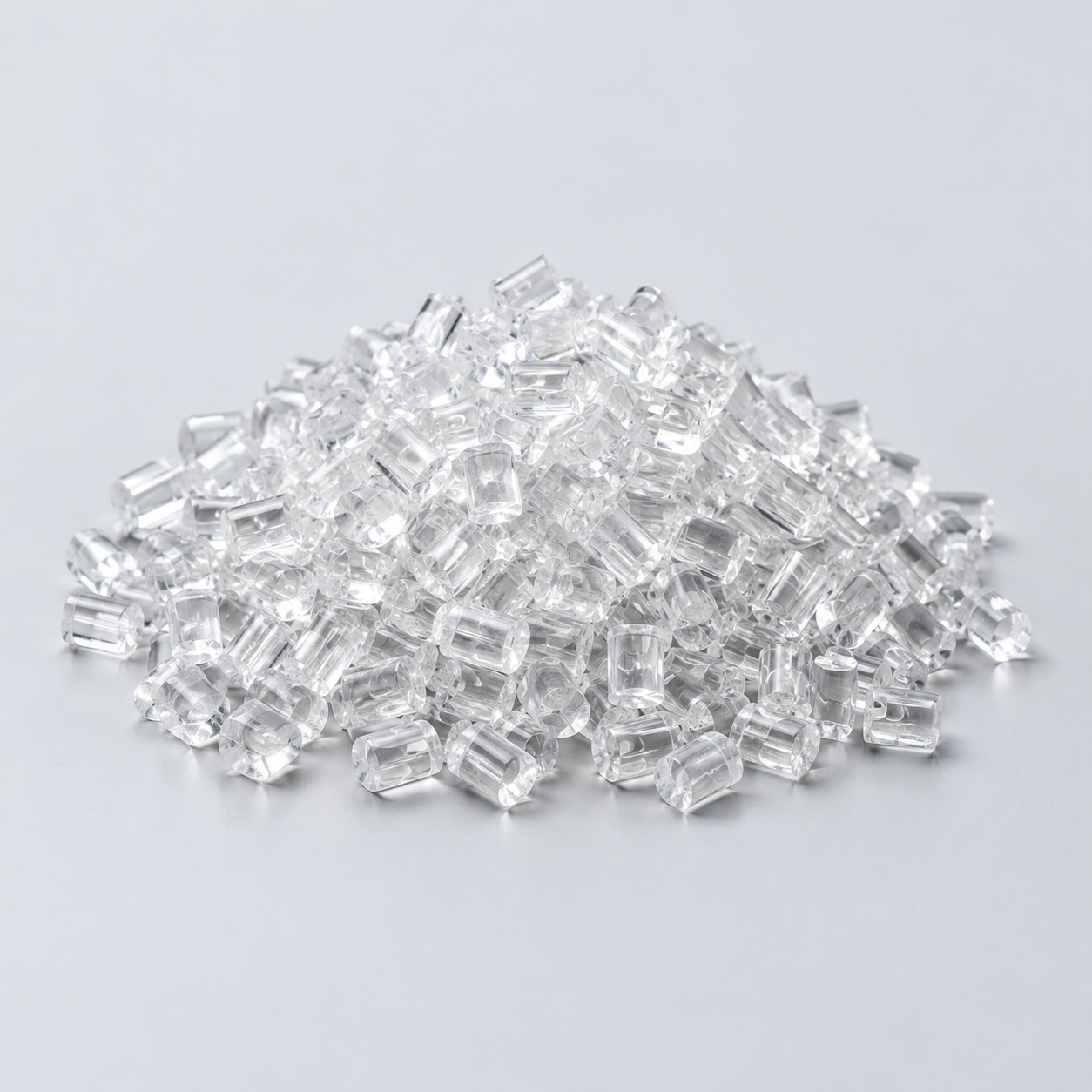 Polycarbonate (PC)Discuss clarity and impact needs›
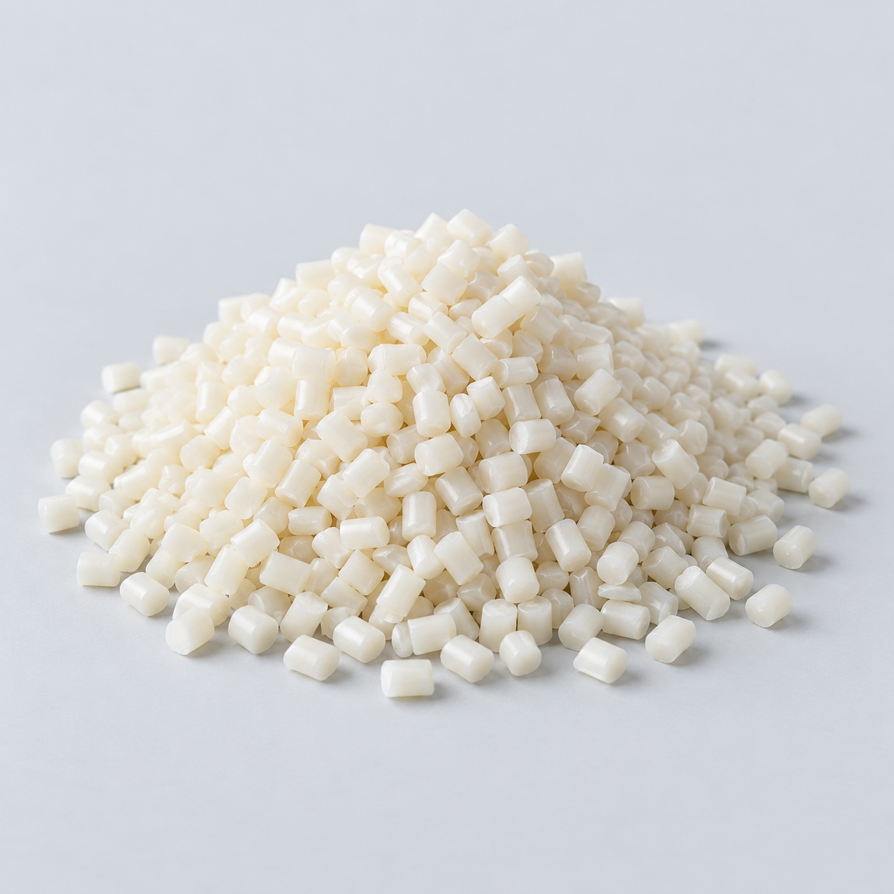 Nylon (PA)Review moisture and wear conditions›
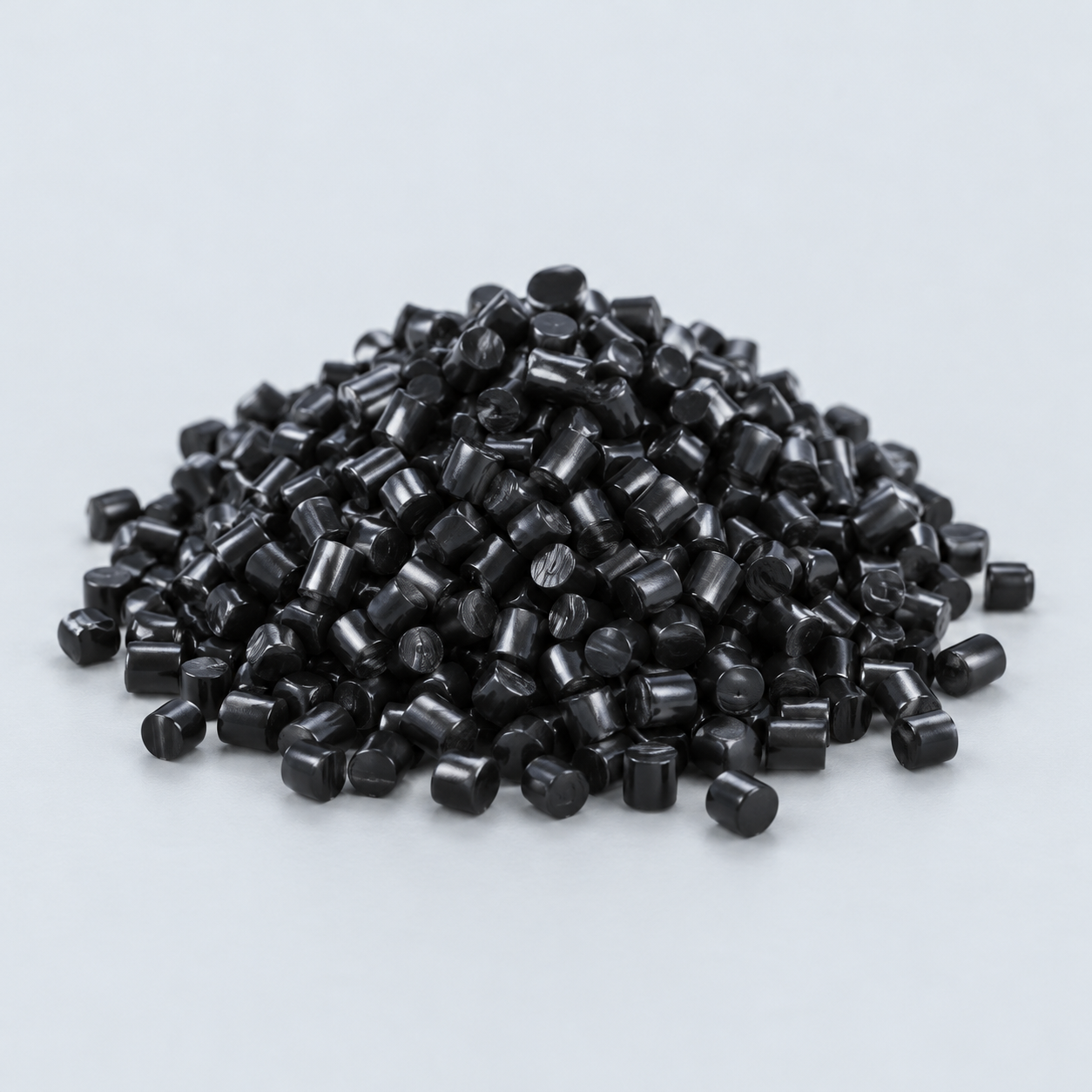 POM / AcetalReview fit and sliding features›
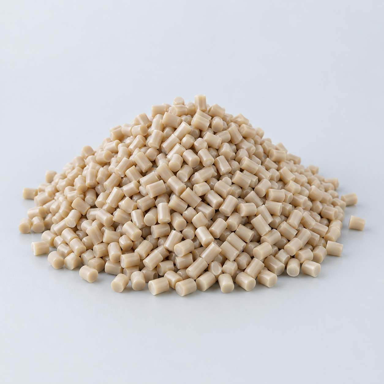 PEEKDiscuss operating conditions›
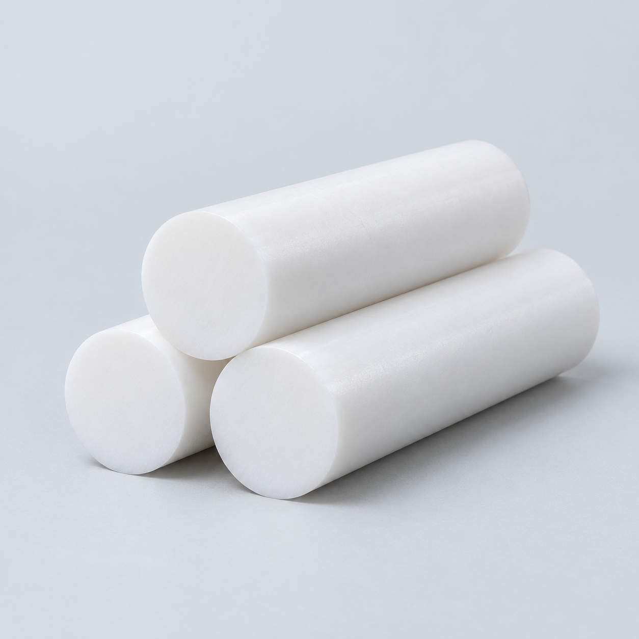 PTFEReview friction and chemical exposure›
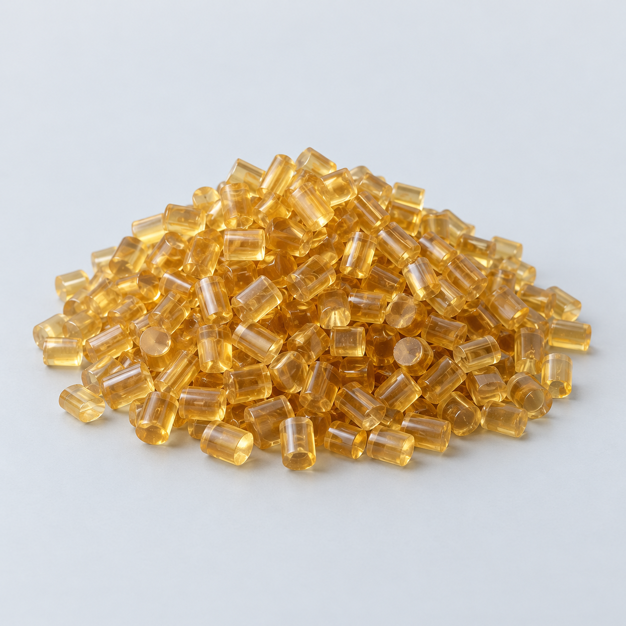 ULTEM / PEIDiscuss thermal and electrical needs›
Confirm grade availability and application requirements.
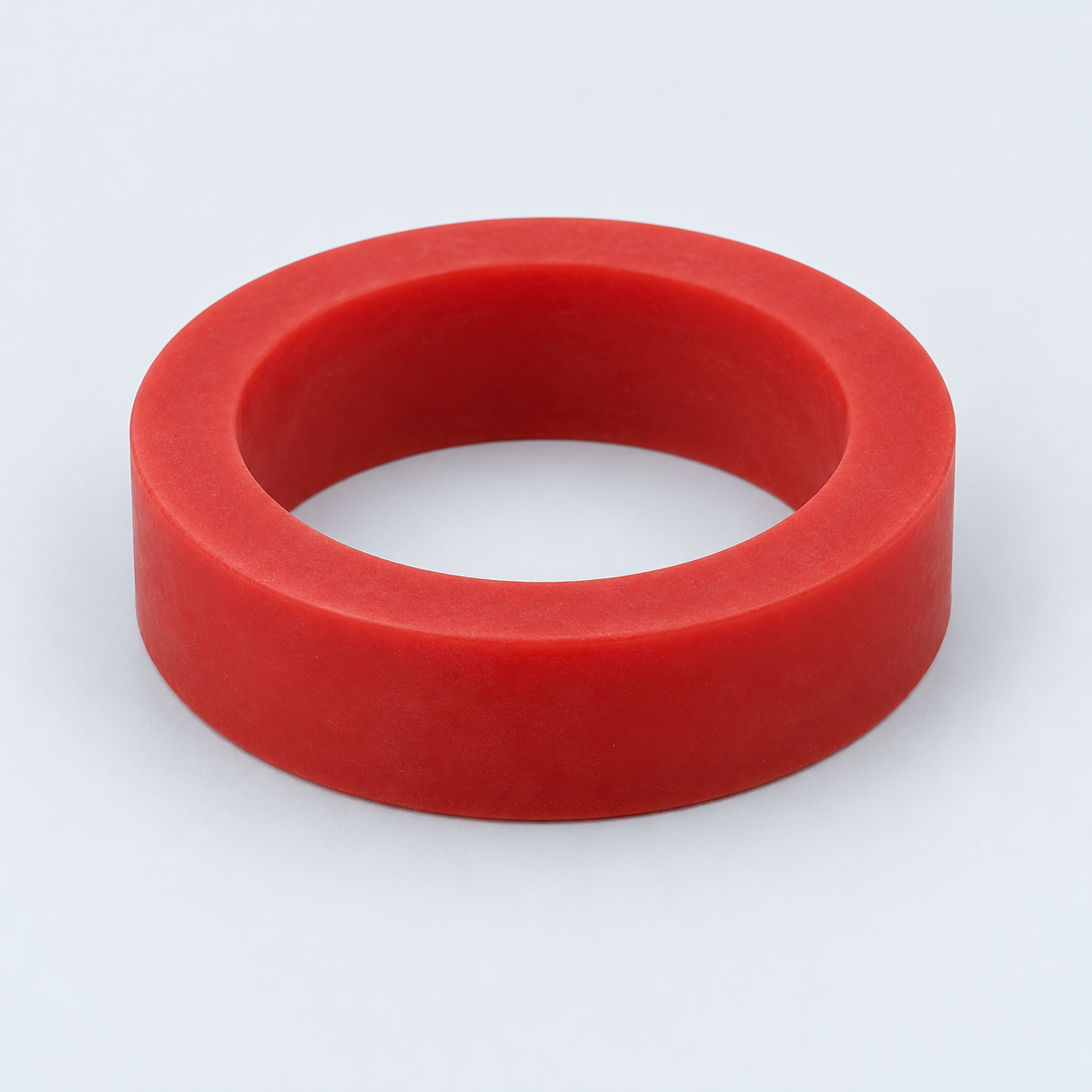 Silicone / LSRDiscuss flexible component needs›
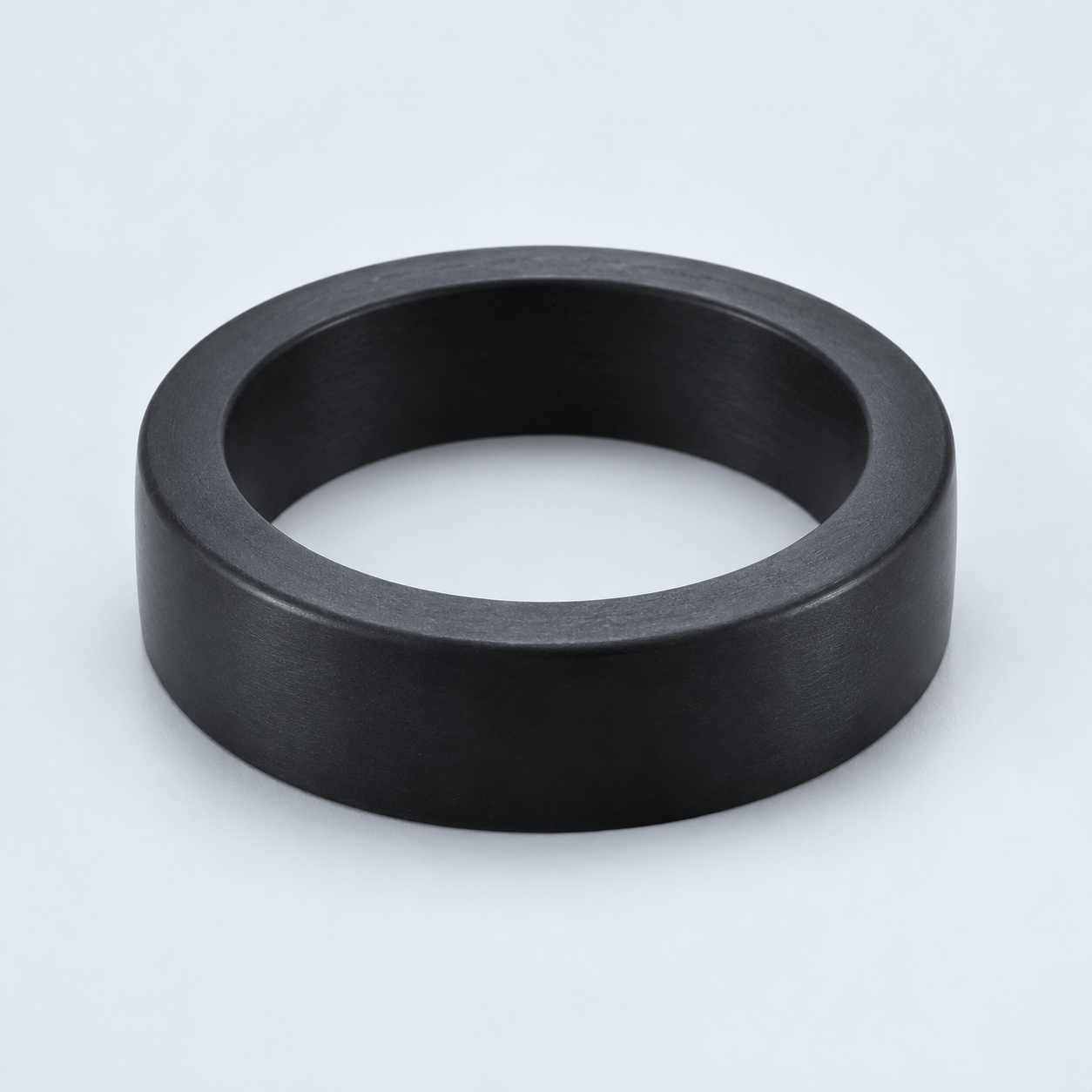 TPU / TPEReview flexibility and processing›
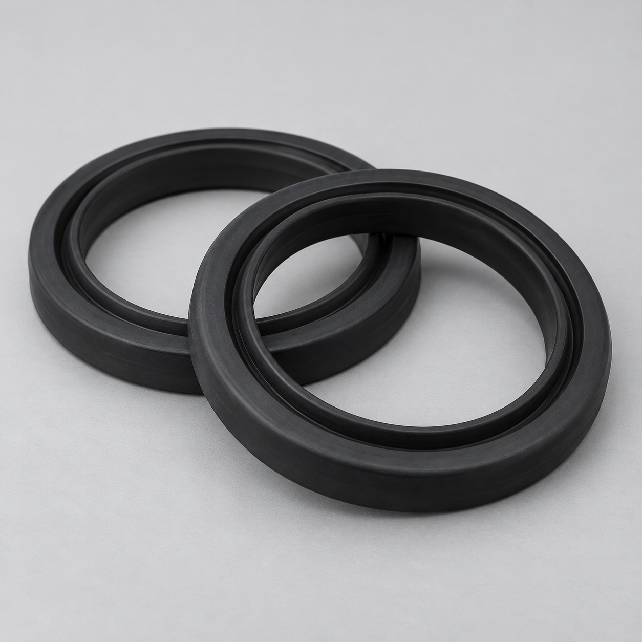 EPDMReview weathering and chemical exposure.›
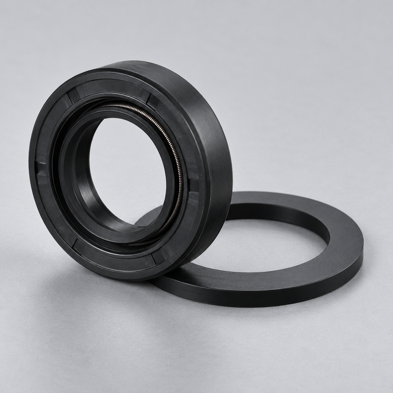 NBRReview oil and fuel exposure.›
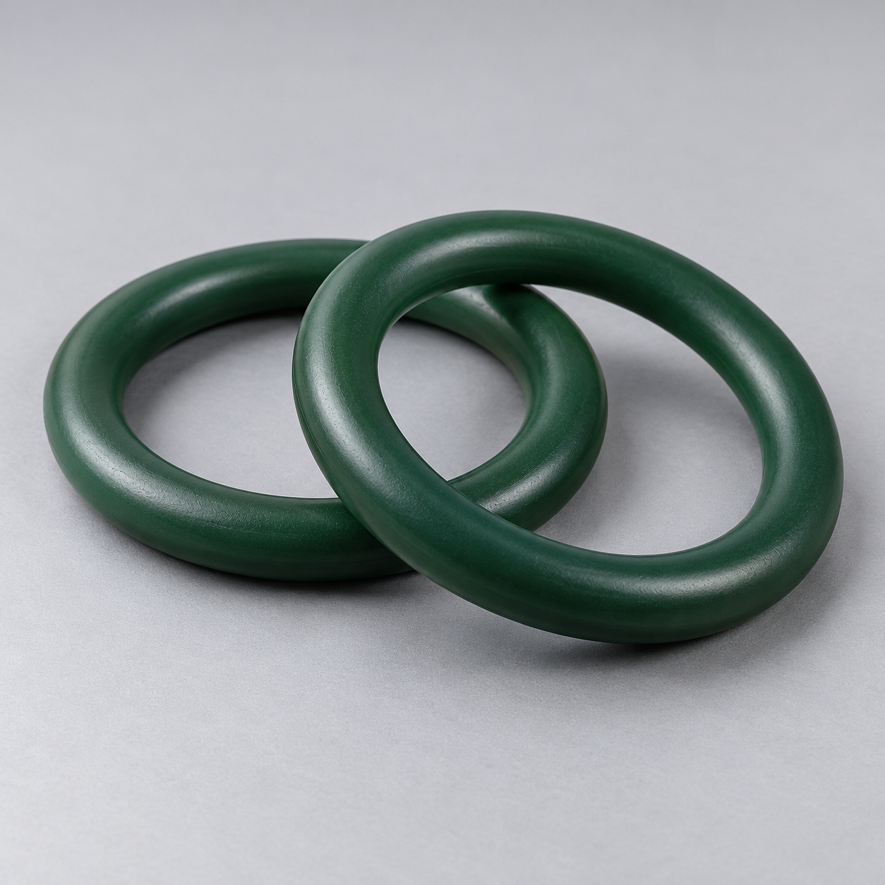 FKMReview temperature and chemical exposure.›
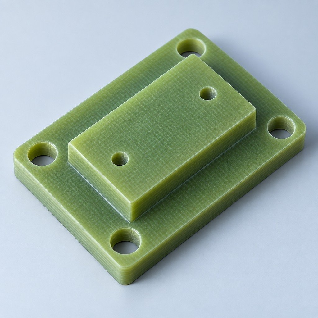 G10 / FR4Review insulation and laminate needs›
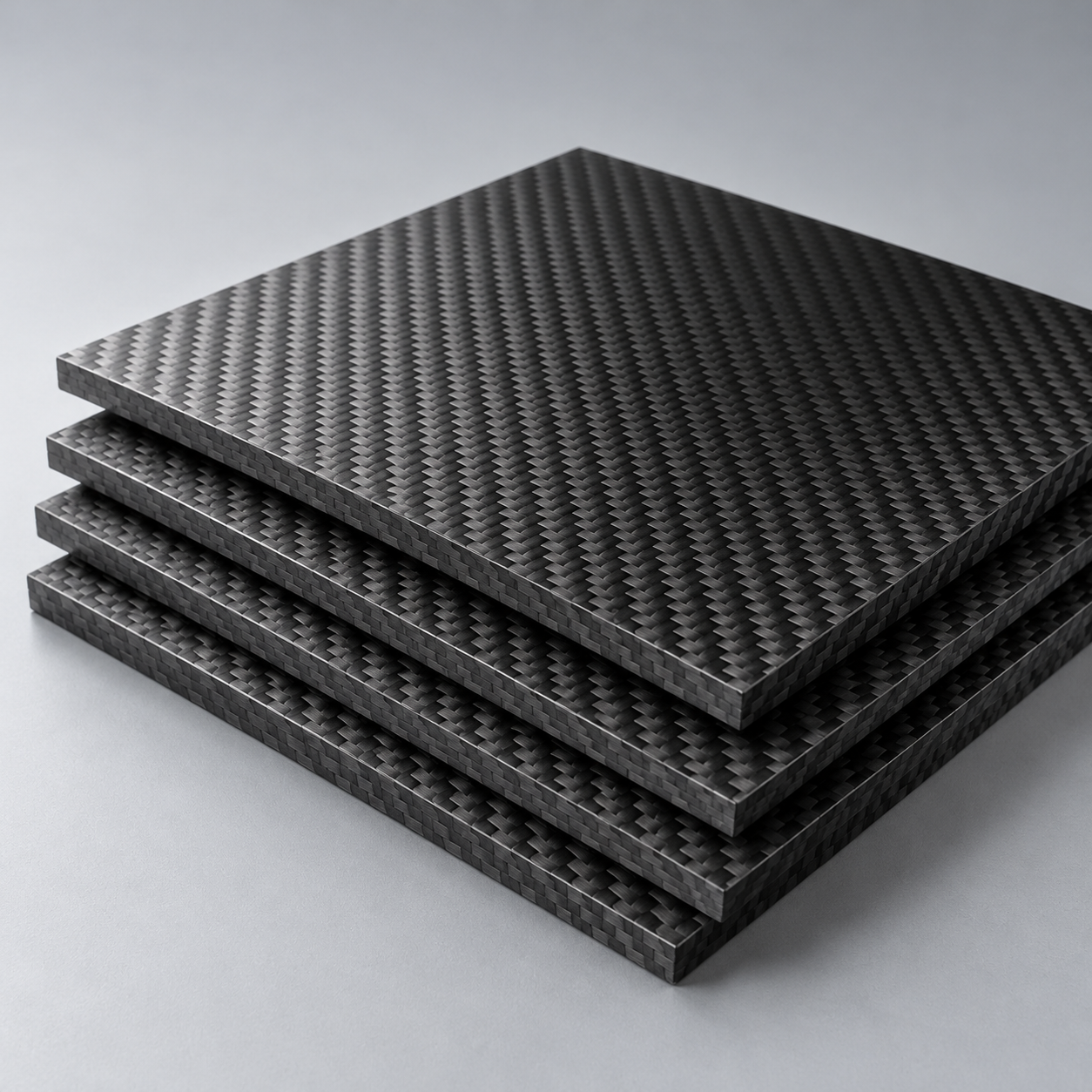 CompositesReview stiffness, weight and laminate.›Customer-Specified MaterialsConfirm your grade and requirements.›Other Specialty MaterialsDiscuss your application and grade.›
Practical guidance for your part geometry and material decisions.
Prepare your process, budget and sourcing questions.
Build your knowledge before production.
Learn who we are and how we operate.
Find our U.S. support team or start a conversation.
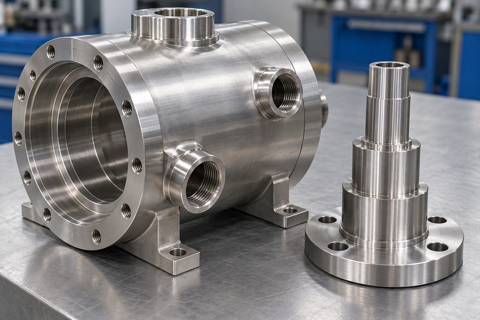
YOUR SERVICE CONDITIONS. YOUR DRAWING. YOUR TRACEABLE RECORDS.
For your oil and gas machined parts supplier review, identify the component’s function, mating interfaces and governing requirements. Share service conditions and required material records before the manufacturing route is agreed.
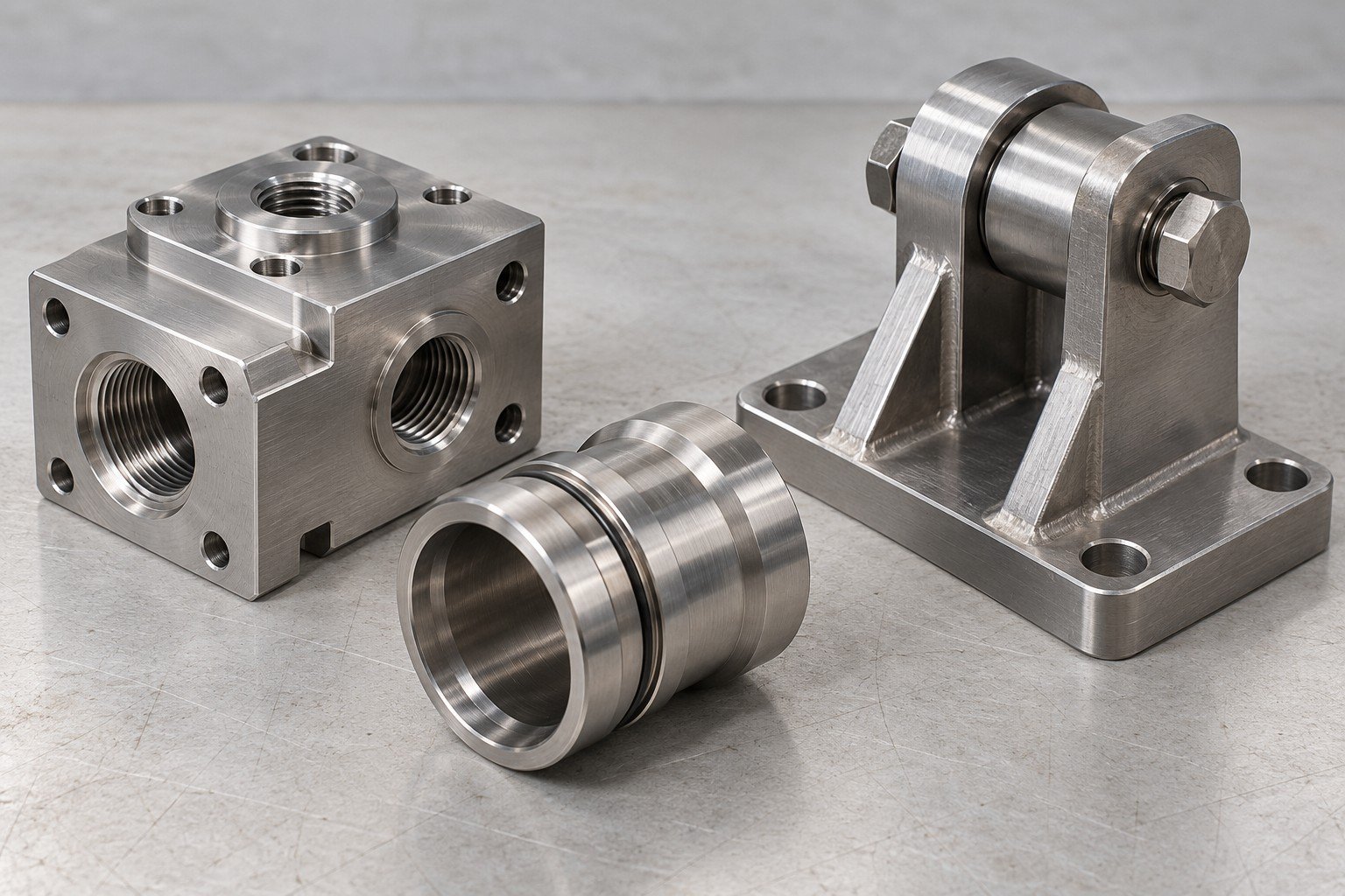
Review sealing lands, threads, bores and access against the released drawing.
Connect mating fits, shoulders and fasteners to the actual assembly.
For custom oilfield equipment components, separate mechanical support scope from pressure-containing or safety-critical approval.
Identify fluid, temperature, exposure and any specified service restrictions.
Share seals, threads, mating hardware and final fit requirements.
State the full specification, condition and required traceability.
Agree inspection, testing, records and approval responsibility.
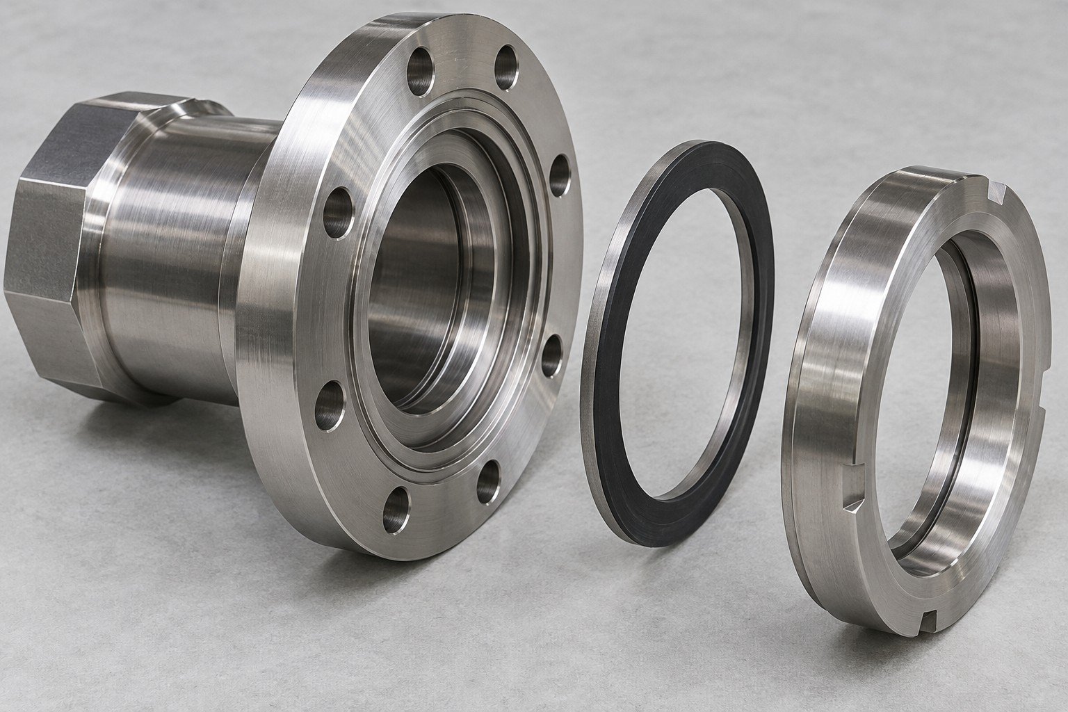
For oilfield equipment precision machining, identify the dimensions and surfaces that control the actual mating assembly.
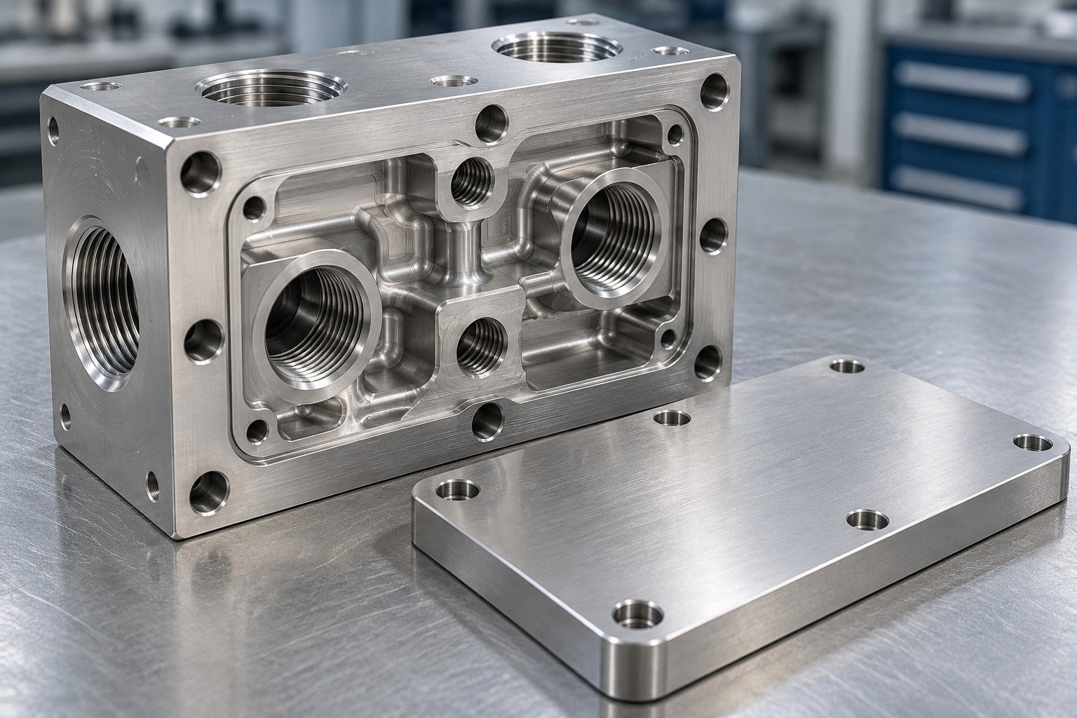
Pressure and exposed area must be considered together. This example illustrates one elementary relationship, not a design or pressure-test recommendation.
Assumed uniform differential pressure over a constant 100 mm² area = 0.00010 m². Force baseline 0–400 N.
1 MPa × 0.00010 m² = 100 N. The other cases use the same assumed area. No component is shown as rated for these pressures.
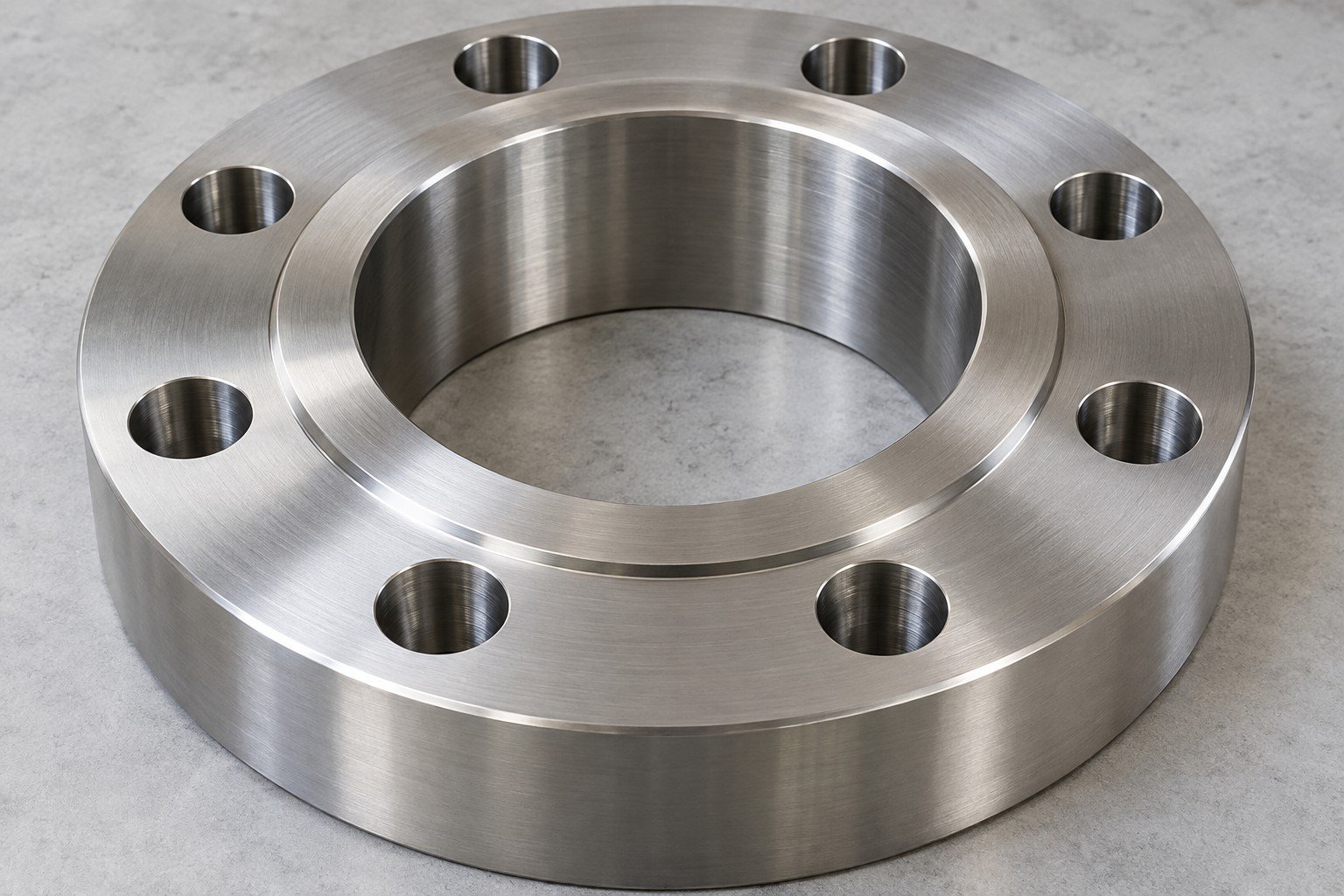
Actual exposed area, stress distribution, wall and joint geometry, temperature, fatigue, seals and applicable design requirements need a component-specific engineering assessment. Dimensional inspection alone does not validate pressure integrity.
Values are calculated examples, not company test results, allowable working pressures or test limits.
For oil and gas prototype machining, state what the sample must demonstrate. A prototype dimensional report does not automatically approve the production material or service performance.
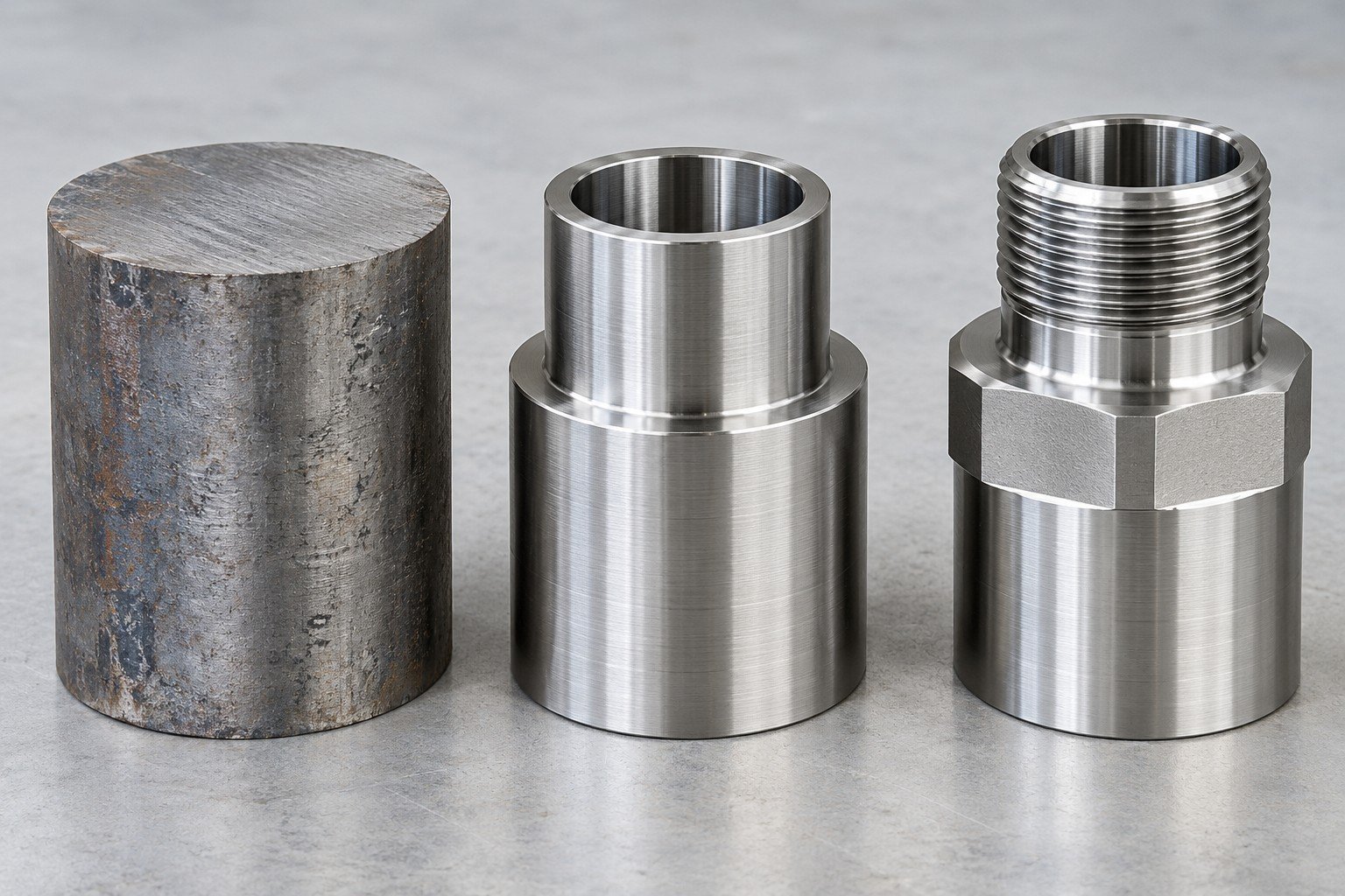
Connect stock form, tool access and secondary operations to the approved drawing.
| Your review | Evidence to agree | Before repeat release |
|---|---|---|
| Functional geometry | Selected dimensions and mating checks | Controlled drawing revision and accepted interfaces |
| Material identity | Specified certificate and lot/heat relationship | Grade, product form and final condition |
| Treatment or outside process | Records required by the order | Provider, process and final acceptance scope |
| Service or pressure validation | Explicitly agreed method, limits and responsible organization | Required approval remains separate from appearance and dimensional checks |
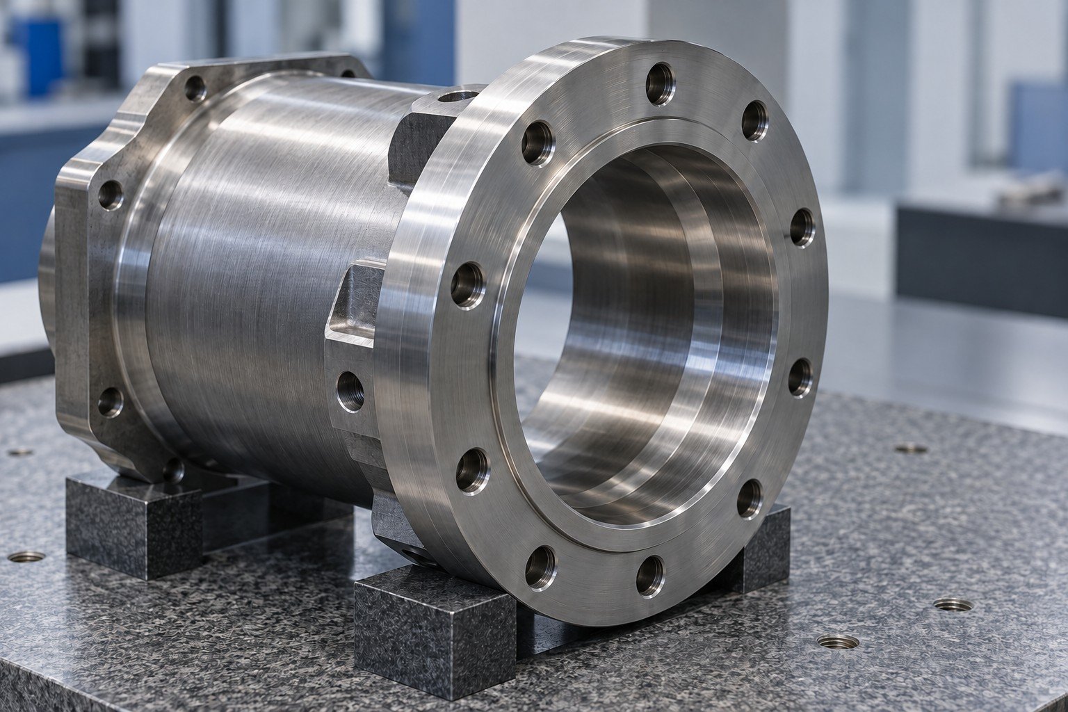
For corrosion resistant oilfield equipment parts, provide the actual service exposure and governing material requirements. Do not infer suitability from the alloy family or a generic corrosion score.
Full material designation, product form and required condition.
Agreed connection between the part, lot/heat and records.
Approve substitutions and condition changes before manufacture.
Agree certificates, dimensions and any separately specified tests.
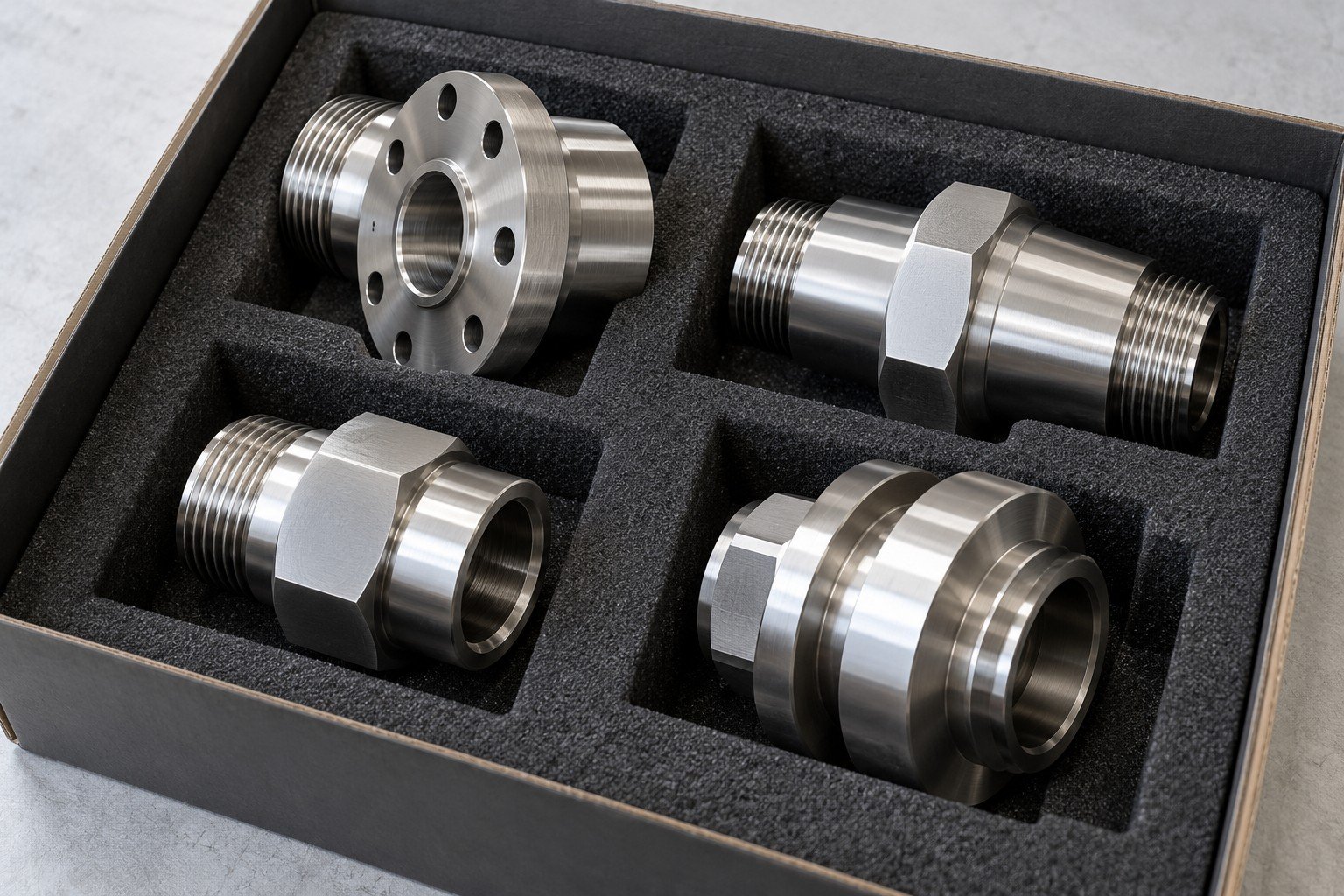
Share the revision, interfaces and actual application.
Review geometry, material and manufacturing sequence.
Check the agreed features and mating condition.
Review specified records and approval responsibility.
Confirm repeat scope, packaging and delivery plan.
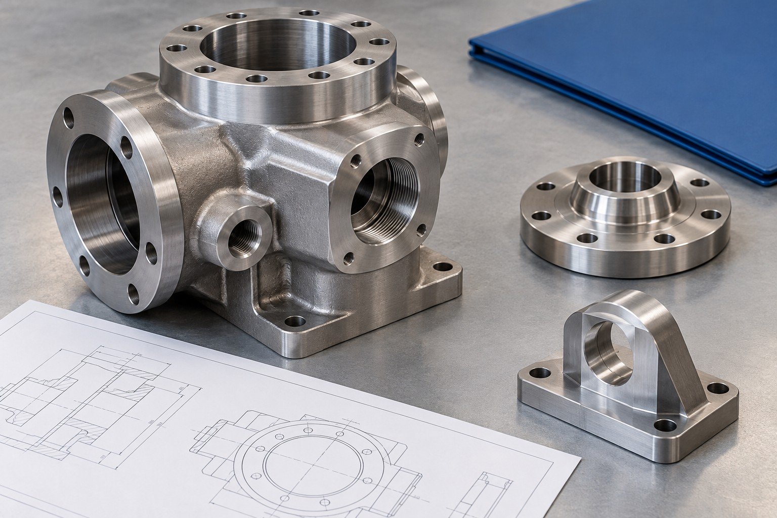
The purchase order and governing specification must define the certificate type, material identity, product condition and required heat/lot traceability. Confirm these before quoting; do not assume one generic certificate covers every application.
No. F = ΔpA relates uniform differential pressure and area to force. It does not establish stresses, fatigue, seals, joint integrity, allowable pressure or test limits.
Only within an agreed approval scope. Confirm the production specification, condition, treatment, traceability and required validation separately.
No approval is implied on this page. Identify the governing requirements and responsible approval organization so the feasible manufacturing and evidence scope can be reviewed explicitly.
Connect interfaces to the manufacturing route. Explore machining →
Review specifications and conditions. Explore materials →
Agree inspection and documentation. Explore inspection →