Injection Molding
Tooling and molding for your repeat plastic parts.
From prototype to production, coordinated manufacturing solutions for your custom parts.
View All Services →
Precision parts for your tight tolerances and complex geometry.
Tooling and molding for your repeat plastic parts.

Metal casting options for your part and production volume.

Cutting, forming and welding for your fabricated parts.

Custom profiles for your section, length and finish requirements.

Finishes for your appearance, corrosion and wear requirements.

Sub-assemblies and final builds for your production program.

Production tooling built around your process and volume.

Prototype parts to check fit, function and design.
DFM, process planning and production support for your project.
Inspection, documentation, inventory and delivery planning for your program.
Choose air- or liquid-cooling components around your thermal and mechanical requirements.

Manufacturing support for your cold plates, manifolds and cooling assemblies.

Find components for your power electronics, energy, laser and telecom application.

Components for your electronic systems.
Start with your functional and quality requirements.
Build around your operating environment.
From prototype to production, review material performance, manufacturability and cost for your part.
Review grade, temper and finish for your metal parts.
 AluminumStrength, weight and machining›
 Stainless SteelCorrosion and finish requirements›
 Carbon & Alloy SteelDiscuss grade and heat treatment›
 Tool SteelDiscuss tooling and wear needs›
 TitaniumReview grade and part geometry›
 Copper & Brass & BronzeDiscuss conductivity and machining›
Match your polymer to function, process and environment.
 ABSReview enclosure and molding needs›
 Polycarbonate (PC)Discuss clarity and impact needs›
 Nylon (PA)Review moisture and wear conditions›
 POM / AcetalReview fit and sliding features›
 PEEKDiscuss operating conditions›
 PTFEReview friction and chemical exposure›
 ULTEM / PEIDiscuss thermal and electrical needs›
Confirm grade availability and application requirements.
 Silicone / LSRDiscuss flexible component needs›
 TPU / TPEReview flexibility and processing›
 EPDMReview weathering and chemical exposure.›
 NBRReview oil and fuel exposure.›
 FKMReview temperature and chemical exposure.›
 G10 / FR4Review insulation and laminate needs›
 CompositesReview stiffness, weight and laminate.›Customer-Specified MaterialsConfirm your grade and requirements.›Other Specialty MaterialsDiscuss your application and grade.›
Practical guidance for your part geometry and material decisions.
Prepare your process, budget and sourcing questions.
Build your knowledge before production.
Learn who we are and how we operate.
Find our U.S. support team or start a conversation.
YOUR INTERFACES · YOUR CONDITIONS · YOUR ACCEPTANCE
Build your review around the connection between each fin and the base. Compare material combinations, fin spacing, bondline control and the evidence you need before approving a bonded fin heat sink.

Illustrative component concept
Critical geometry & interfaces
Grades, condition & compatibility
Defined route & final state
Agreed methods & records
Review fin geometry, the actual joining route and your installed conditions together. Define the final fit and evidence before approving the assembly.
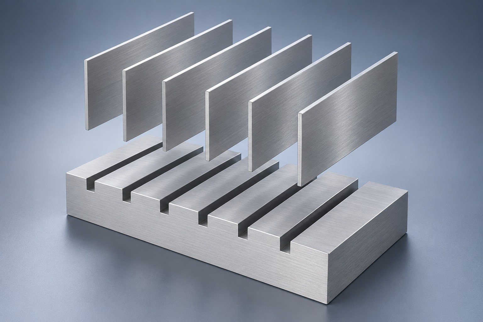
Specify fin thickness, clear spacing, height and the base-slot layout.
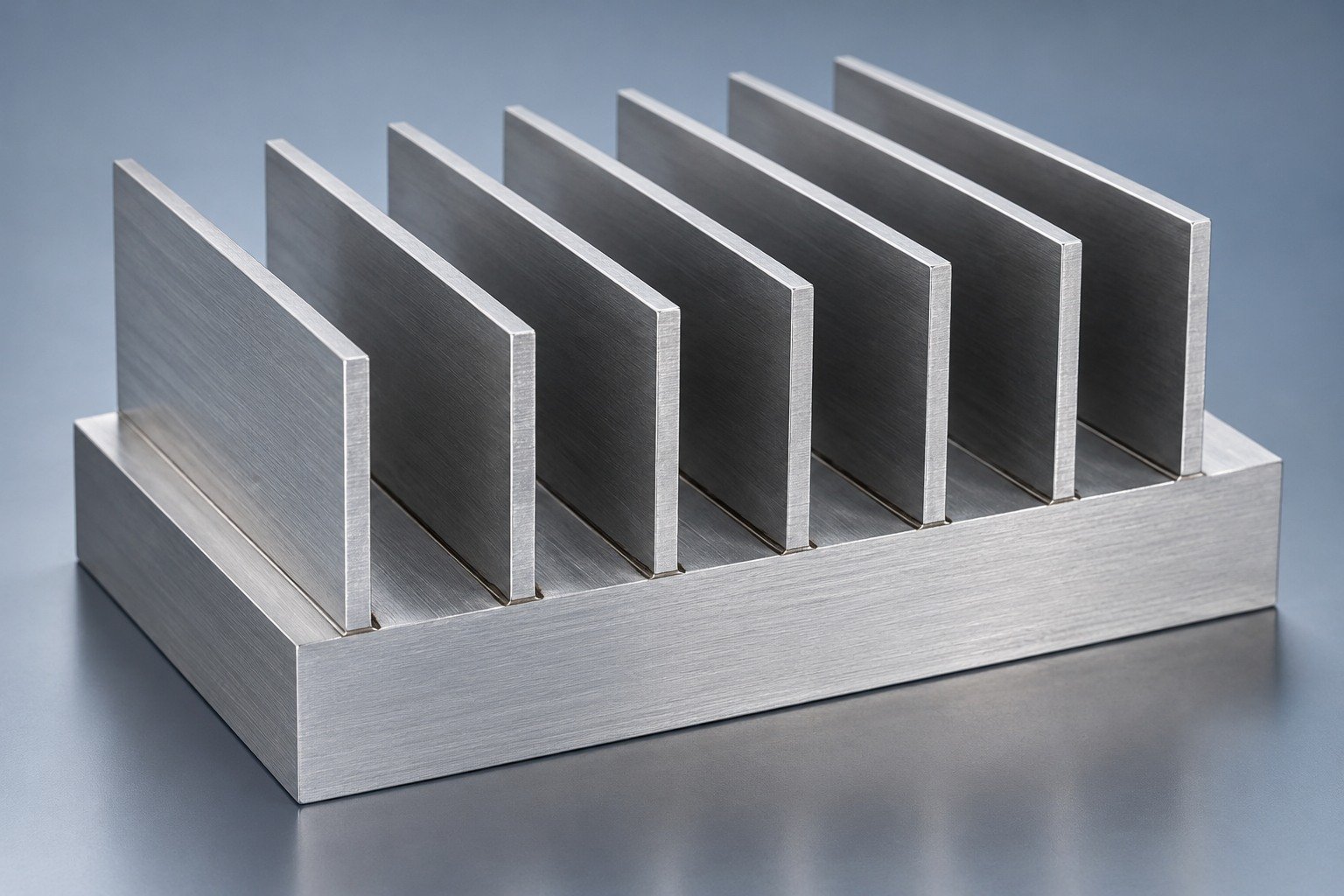
Identify the adhesive or metallurgical joining route; do not leave the joint as an unstated assumption.
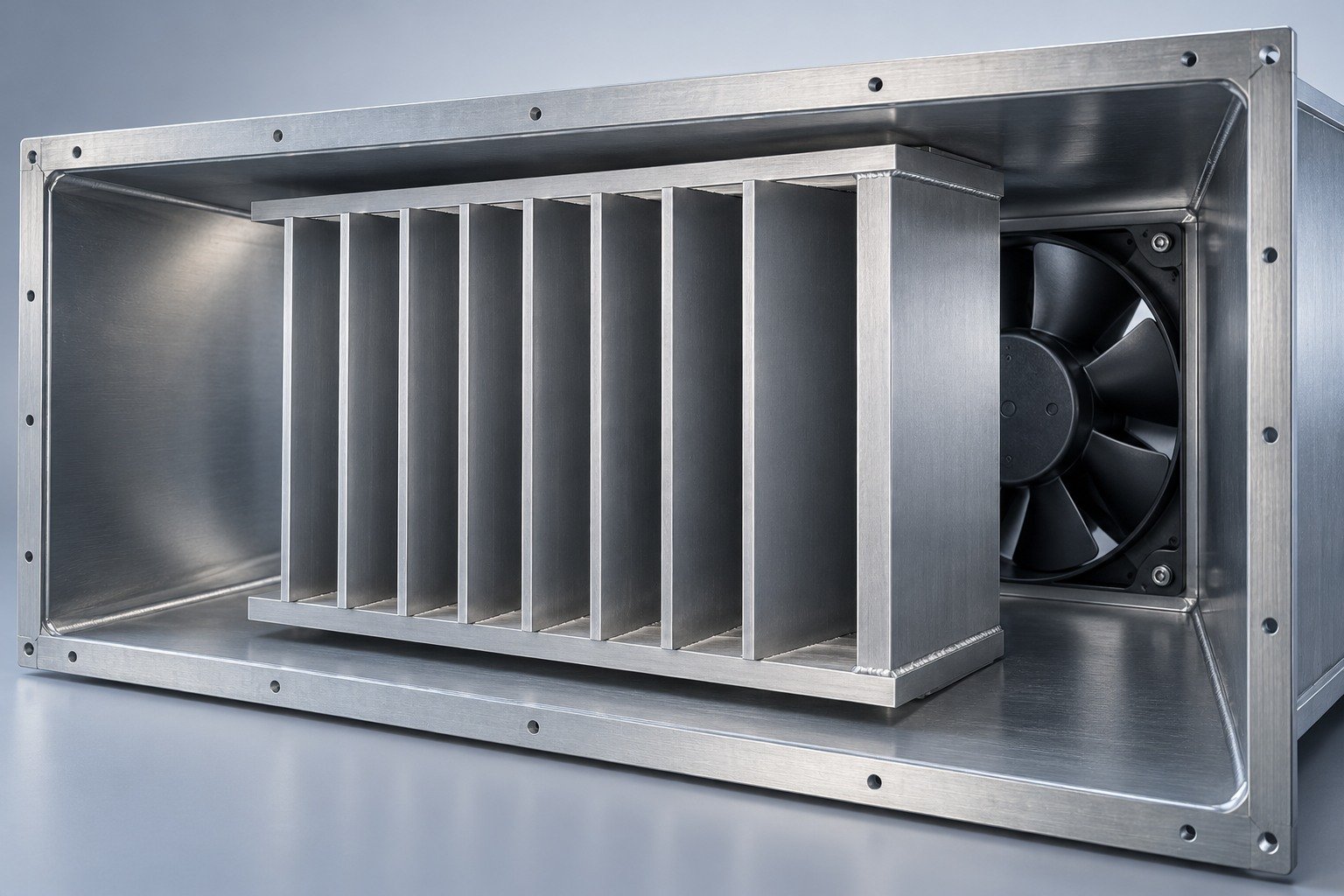
Share temperature range, thermal cycles, vibration and the installed airflow.
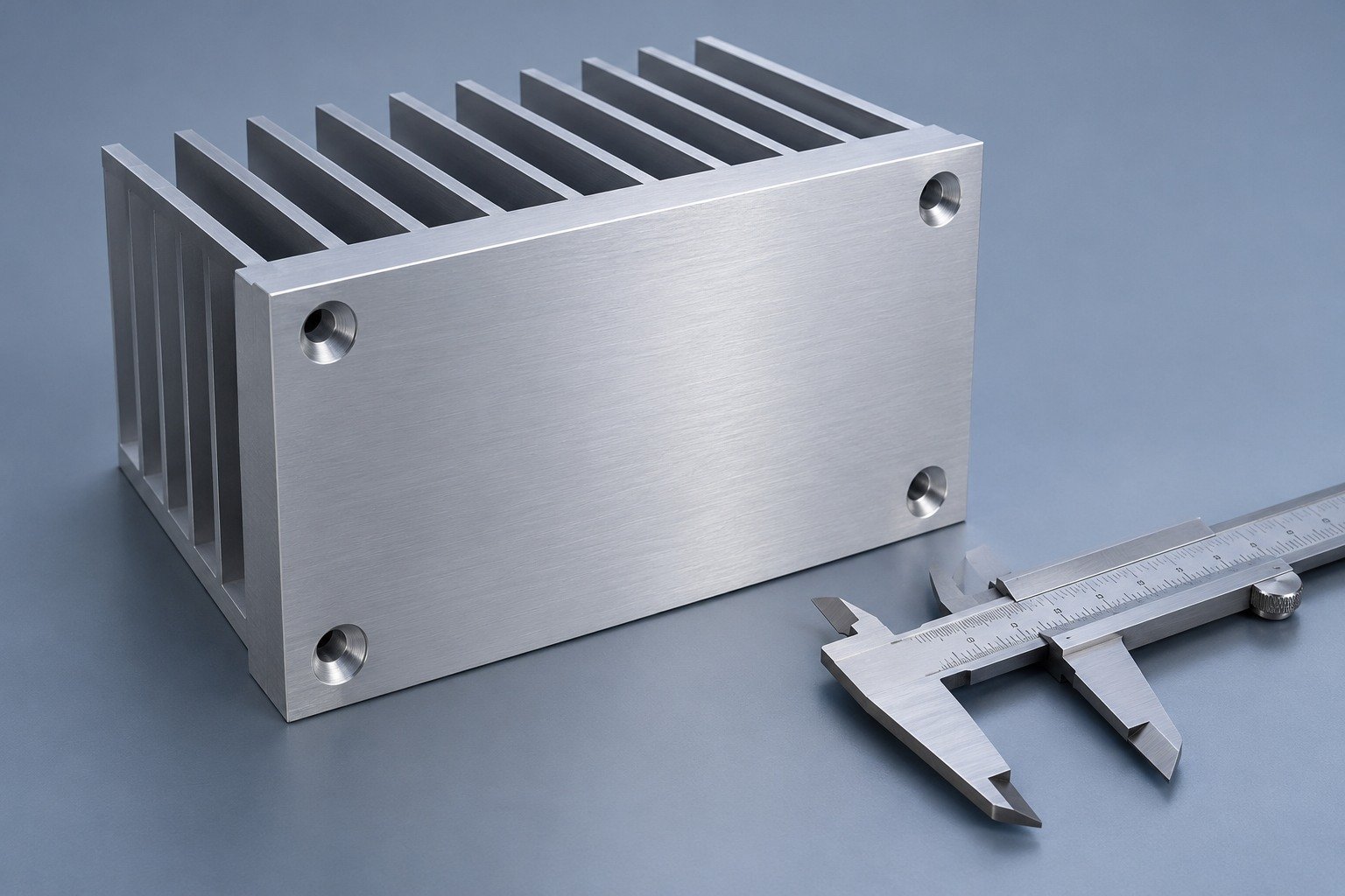
Define mounting datums and heat sink base flatness after joining and any final machining.
Illustrative engineering concepts
Compare the joint route and acceptance needs together. Your drawing and service conditions determine suitability; the images illustrate structures, not confirmed company capability.
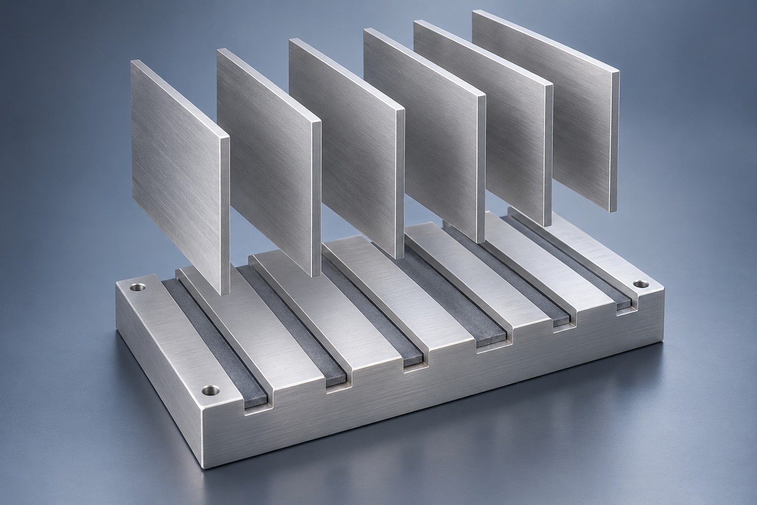
Define surface preparation, adhesive, bondline and service conditions.
Review route requirements →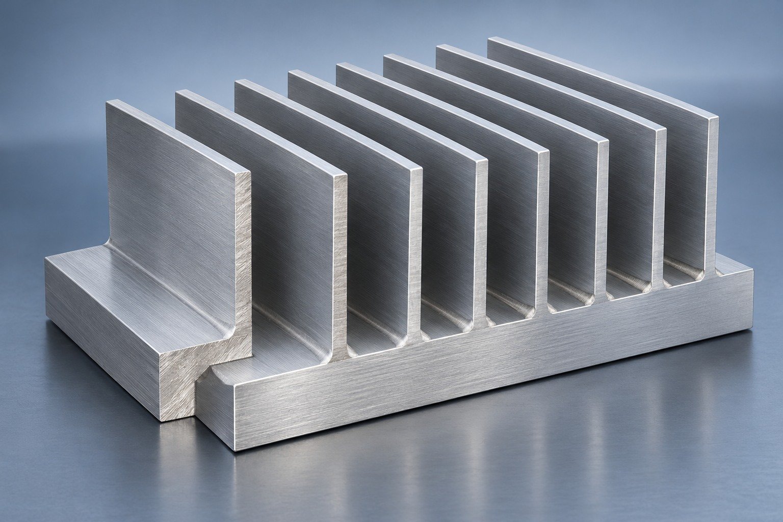
Review base, fins, filler, joining access and the final inspection state.
Review route requirements →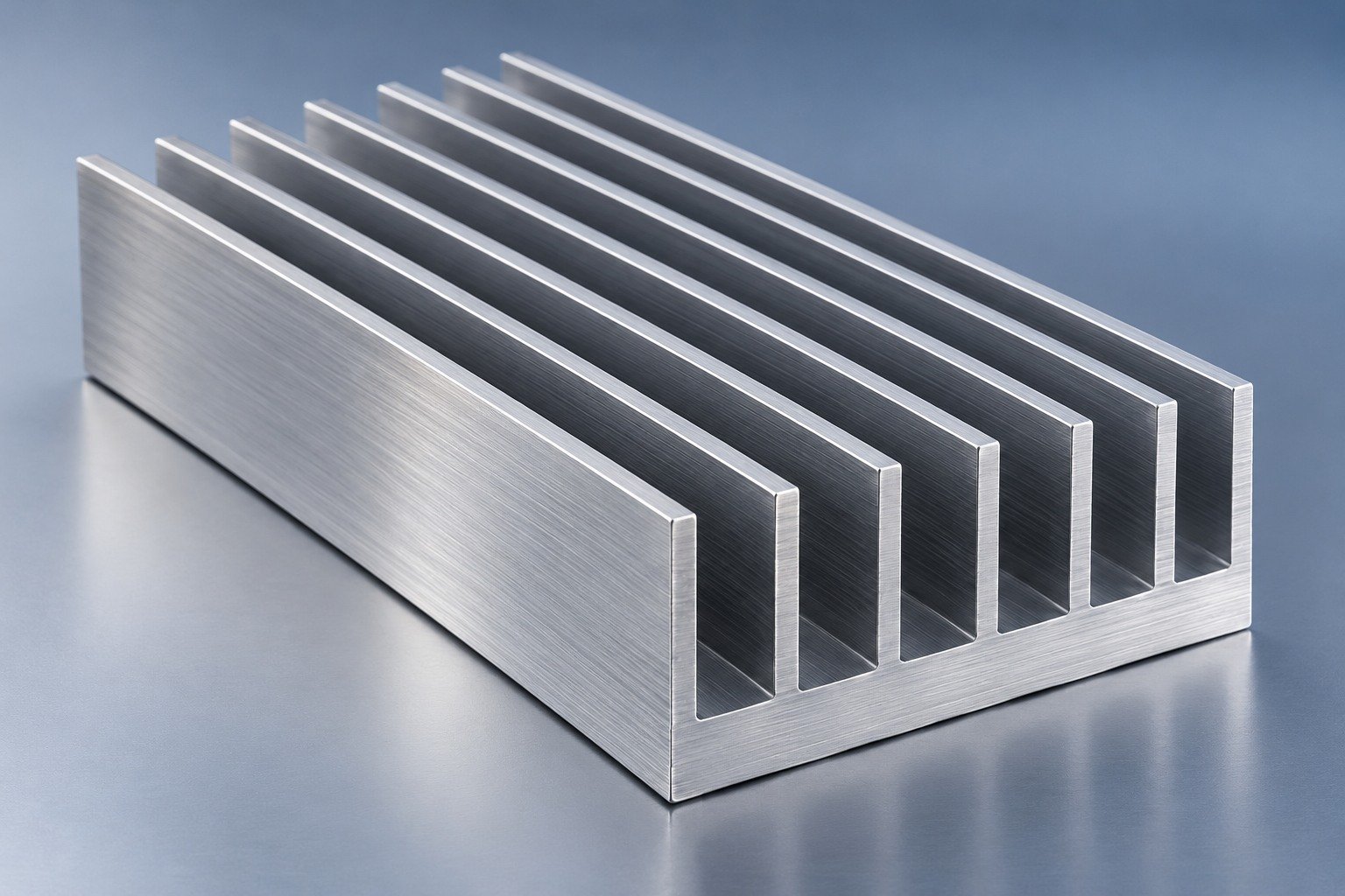
Compare a one-piece profile when its geometry and order scope suit your assembly.
Review route requirements →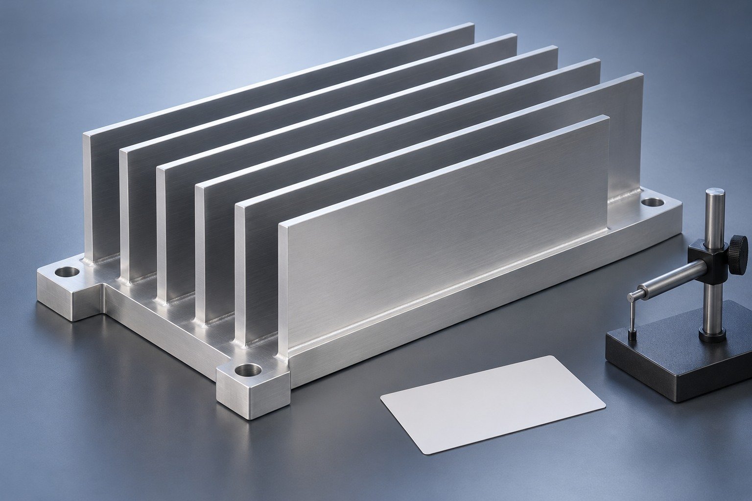
Record the selected materials, joining route, final features and acceptance evidence.
Review route requirements →Illustrative engineering concepts
Separate fins seated in a base let you review fin geometry and base features independently. Your bonded fin heat sink manufacturing service must define the actual joining route: an adhesive joint and a brazed joint need different materials, processing and acceptance evidence.
Bulk stock properties help you review conduction and mass. These are sourced material references, not LK MFG part tests, approved material substitutions or post-joining performance guarantees.
Hydro 6061-T6 at 25°C; Gabrian 6063-T5 typical. KME Cu-ETP annealed at 20°C.
Calculate finished mass from the actual geometry. A material conductivity difference does not establish a device-temperature reduction.
| Grade | European reference | Si | Fe | Cu | Mn | Mg | Zn | Al |
|---|---|---|---|---|---|---|---|---|
| 6061 | EN AW-6061 · AlMg1SiCu | 0.40–0.80 | ≤0.70 | 0.15–0.40 | ≤0.15 | 0.80–1.20 | ≤0.25 | Balance |
| 6063 | EN AW-6063 · AlMg0.7Si | 0.20–0.60 | ≤0.35 | ≤0.10 | ≤0.10 | 0.45–0.90 | ≤0.10 | Balance |
| C11000 | Cu-ETP · CW004A | — | — | ≥99.90 | — | — | — | — |
Selected elements only. Dash means not specified in this summary, not zero. 6061: Cr 0.04–0.35%, Ti ≤0.15%; 6063: Cr/Ti ≤0.10% each. C11000: O ≤0.040%; do not relabel Cu-ETP as oxygen-free copper. Aluminum other elements ≤0.05% each / ≤0.15% total. The purchasing standard and certificate govern. Confirm product form, temper, joining compatibility and required final condition.
Sources: Hydro 6061 → · Gabrian 6063 → · KME Cu-ETP →
Use calculations to frame your questions. Request measured curves or CFD only with an agreed geometry, boundary conditions and validation scope. Every example here is illustrative.
Hypothetical example only: R = t/(kA), with k = 1 W/(m·K), A = 0.01 m² and t as labelled. These chosen inputs are not an adhesive data sheet, a validated bondline or a finished heat sink test.
Chosen example: 75°C limit minus a reference of 25, 35 or 45°C gives 50, 40 or 30 K. Define whether your reference is ambient, inlet fluid or another measurement point.
A conceptual path, not a CFD result. Agree heat-source area, power, contact stack, sensor locations, airflow and orientation.
Review thermal contact faces, mounting features and fin handling separately. Confirm finish compatibility with the specified joint and service environment.
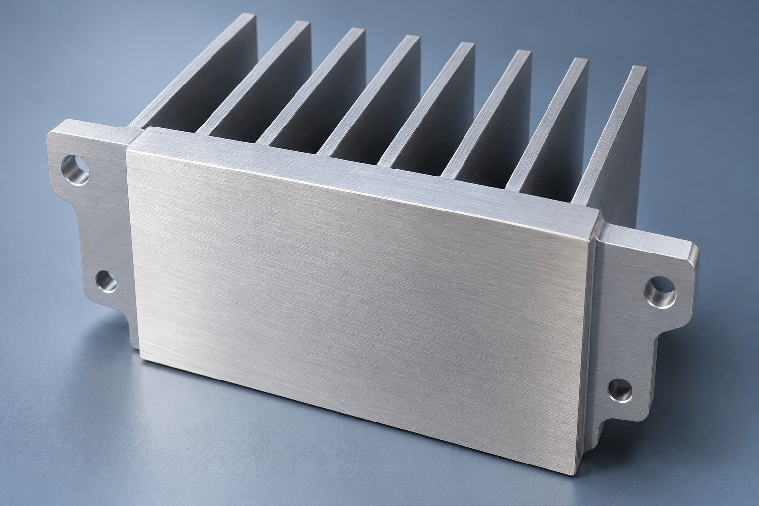
Define the final contact pad, coating exclusions and inspection state.
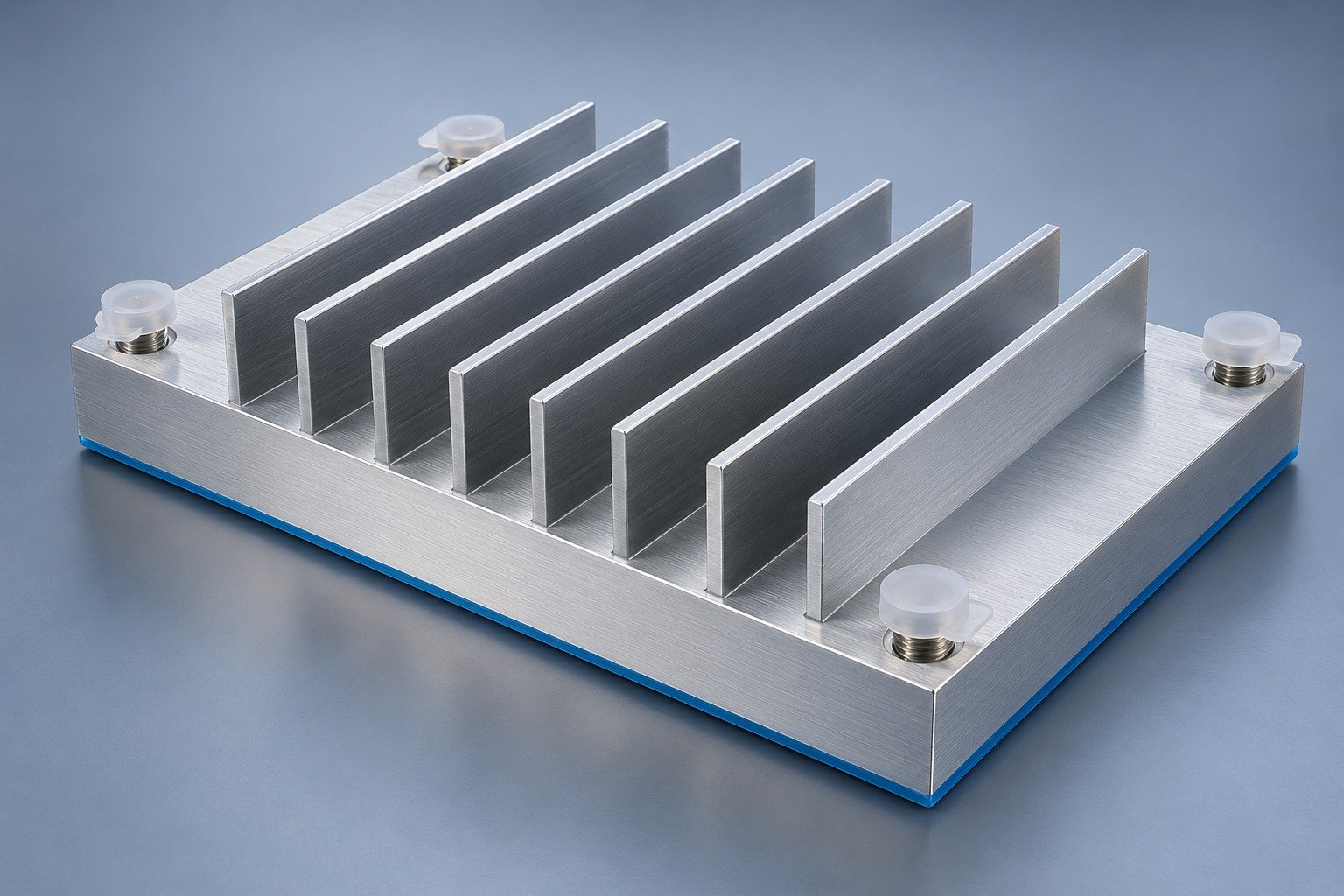
Protect critical threads, interfaces and joint surfaces according to the agreed finishing route.
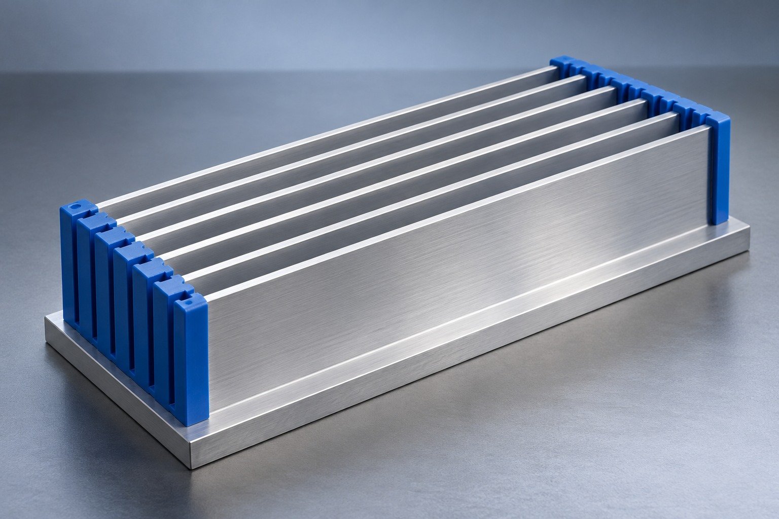
Agree cleaning access, fin protection and handling that preserves the released geometry.
A finish is not a universal cooling improvement. Confirm its purpose, compatibility and inspection state. Review surface finishing options →
Illustrative engineering concepts
Put the fin layout, joining interfaces, final contact area and assembly datums on your drawing.
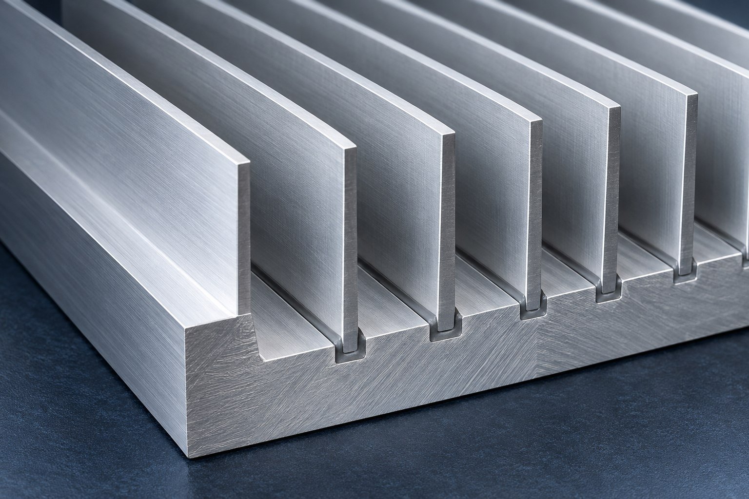
Illustrative fin-to-base joint concept
Heat-source map, TIM and clamping stack
Slot engagement, joint route and surface preparation
Hole pattern, datum scheme and tool access
Thickness, spacing, height and airflow orientation
Flatness, masking, protected interfaces and inspection state
Review your fin joint, installed airflow, final fit and acceptance evidence before production.
Agree a fin bond integrity verification method, sampling and acceptance criteria. A visual check alone does not establish bond strength.
Controlled drawing and the relevant service conditions.
Agreed method, inspection state, limits and required records.

Illustrative engineering concept
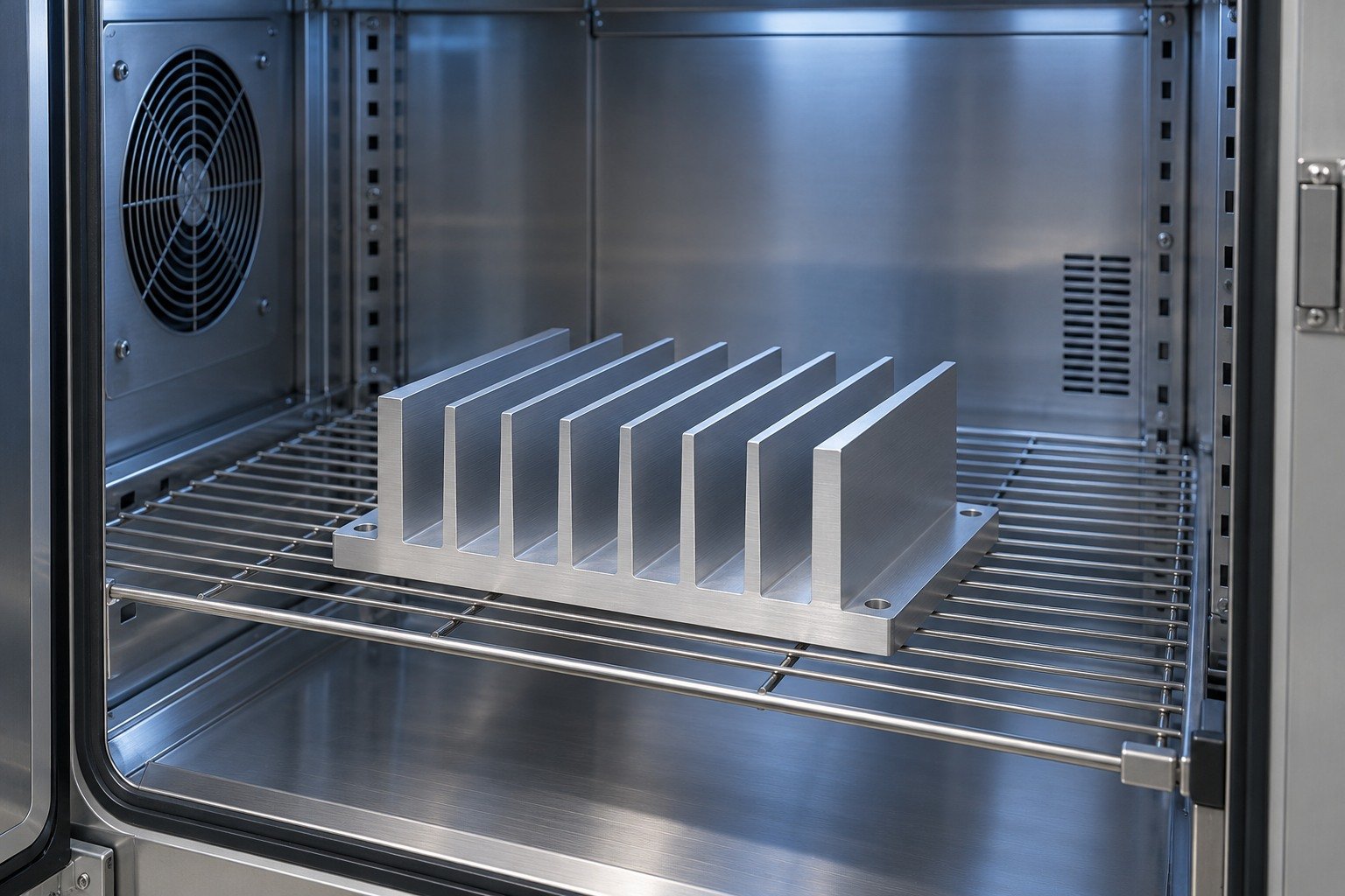
For bonded heat sink thermal cycling, specify cycle limits, dwell, transitions, number of cycles and the checks before and after cycling.
Controlled drawing and the relevant service conditions.
Agreed method, inspection state, limits and required records.
Illustrative engineering concept
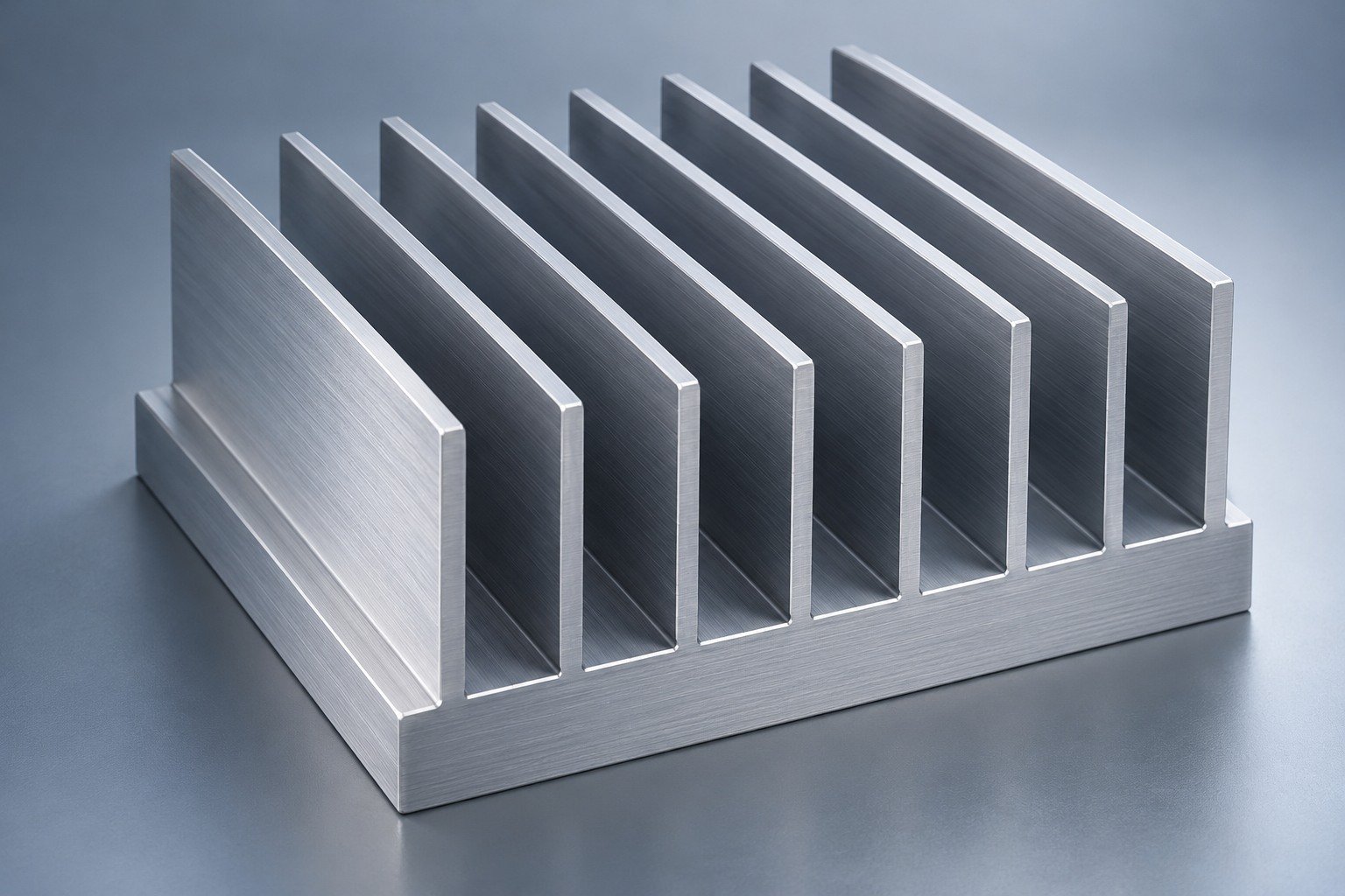
Review bonded fin heat sink fin spacing against installed airflow, cleaning access and the protection needed during handling.
Controlled drawing and the relevant service conditions.
Agreed method, inspection state, limits and required records.
Illustrative engineering concept
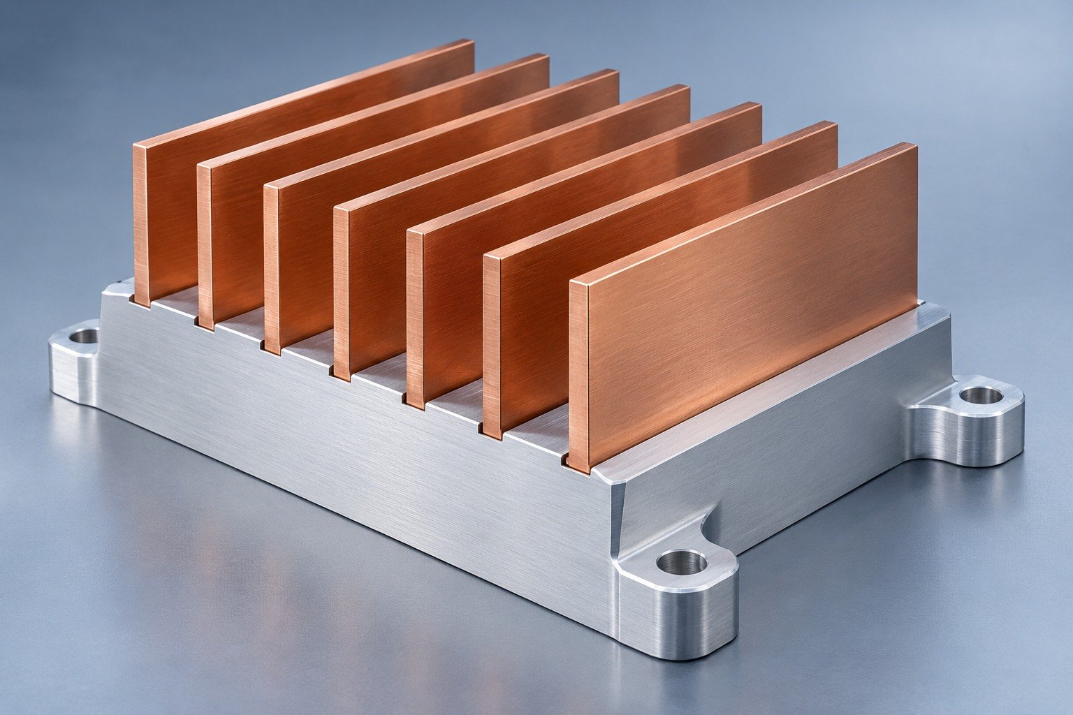
Copper fins with an aluminum base require review of the joining method, expansion mismatch, environment and corrosion protection.
Controlled drawing and the relevant service conditions.
Agreed method, inspection state, limits and required records.
Illustrative engineering concept
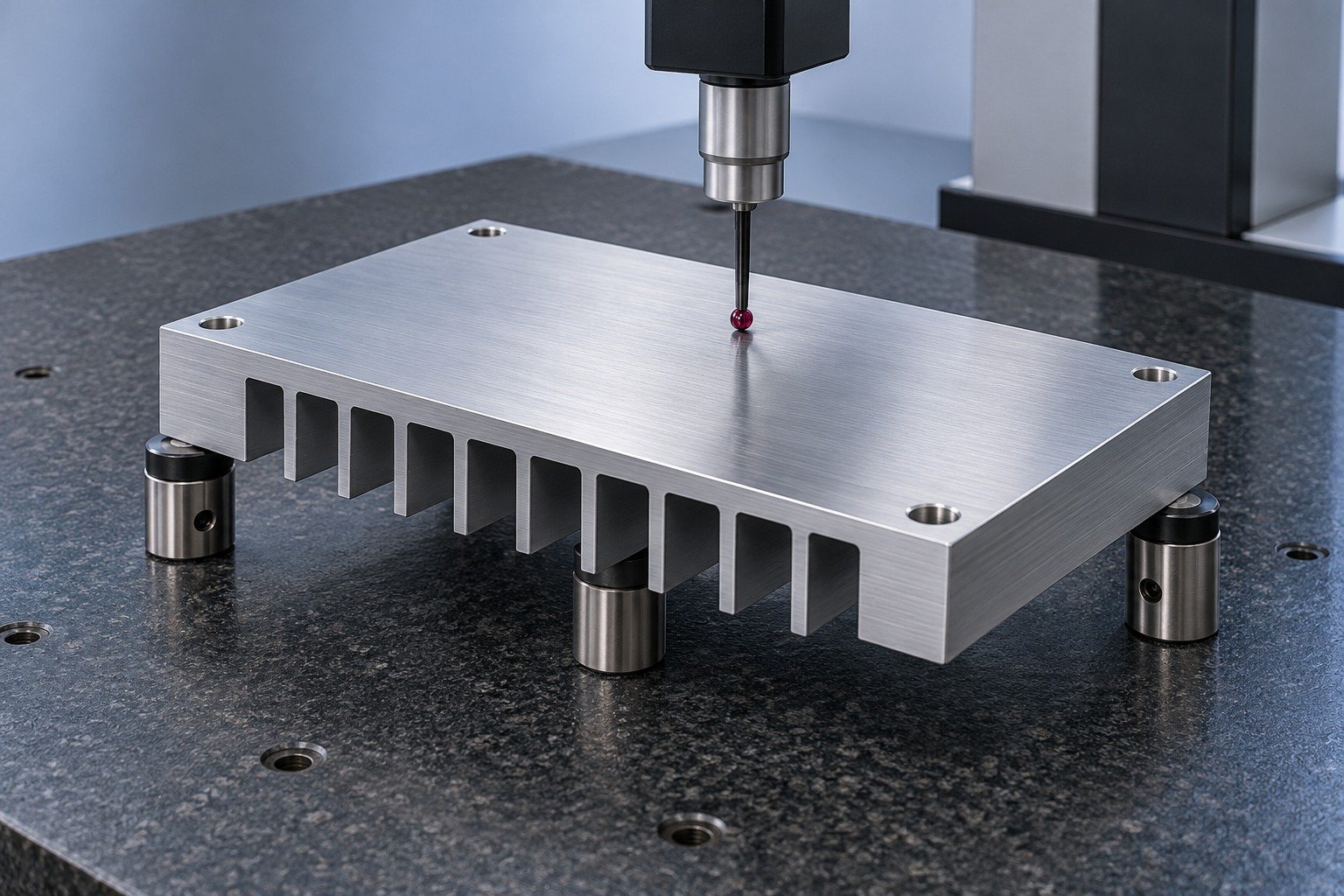
Specify the final inspection state, datums, restraint and contact area; assess distortion after the joining operation.
Controlled drawing and the relevant service conditions.
Agreed method, inspection state, limits and required records.
Illustrative engineering concept
For bonded fin heat sink machining, agree which base features are cut before joining and how finished fins are supported and protected.
Controlled drawing and the relevant service conditions.
Agreed method, inspection state, limits and required records.
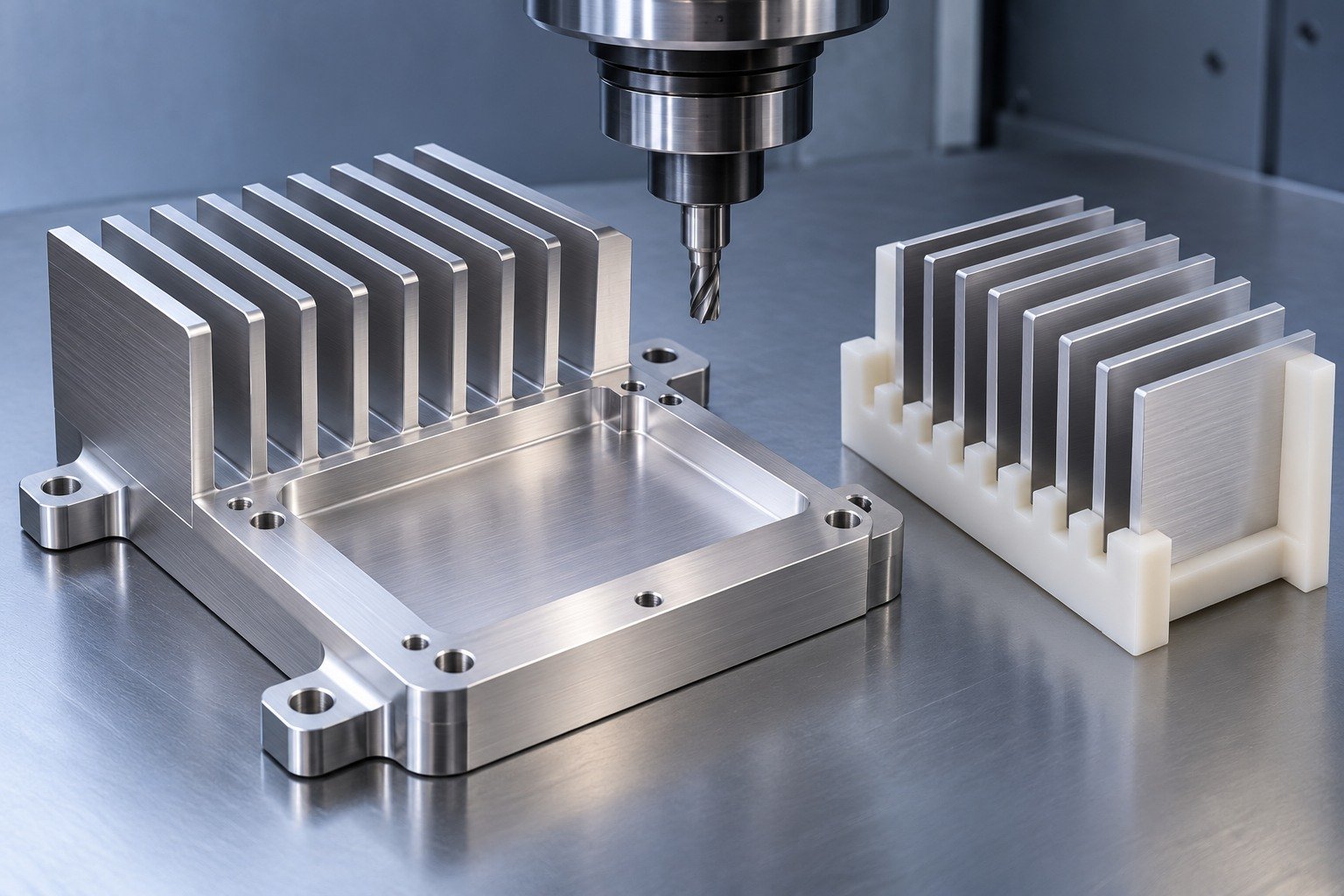
Illustrative engineering concept
Confirm revision, interfaces and operating inputs.
Agree materials, joining and final machining.
Review the finished component and assembly fit.
Assess specified dimensions, joints and test records.
Release the accepted revision, packaging and repeat-order scope.
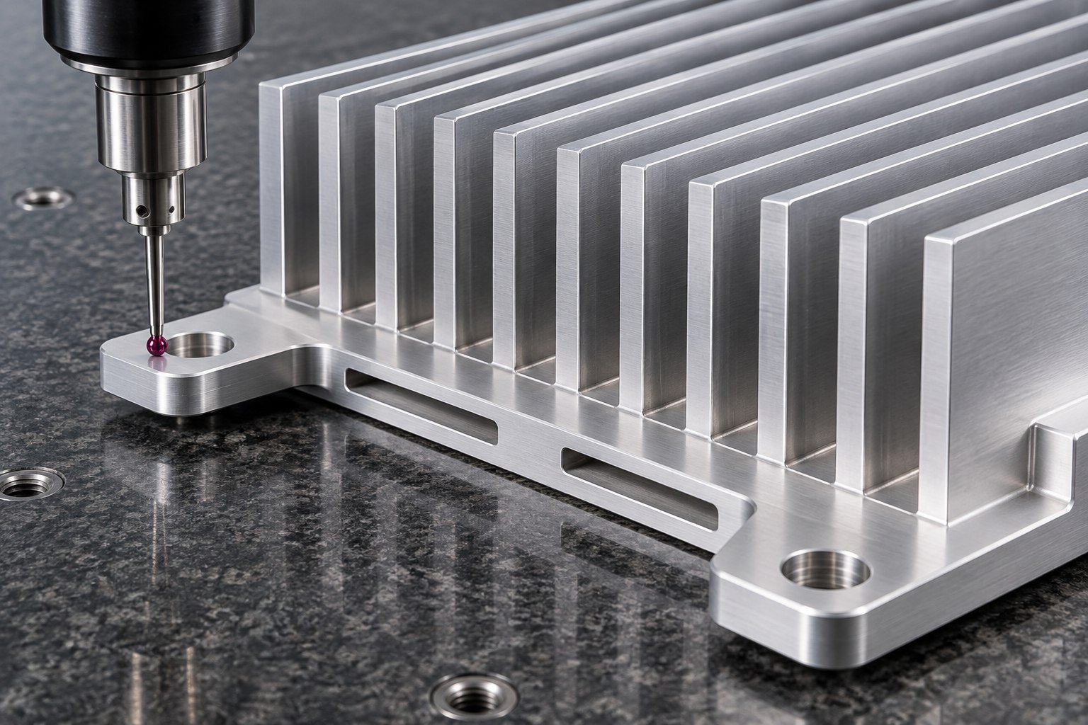
Illustrative component concept
Your prototype bonded fin heat sink should establish drawing revision, material identity, joint process and the agreed inspection plan. Bond strength, thermal cycling and thermal resistance are separate requirements with their own conditions; agree which records belong in your sample package.
Project suitability, manufacturing scope and required records are confirmed from your drawing. These are application review topics, not customer case studies or system certifications.
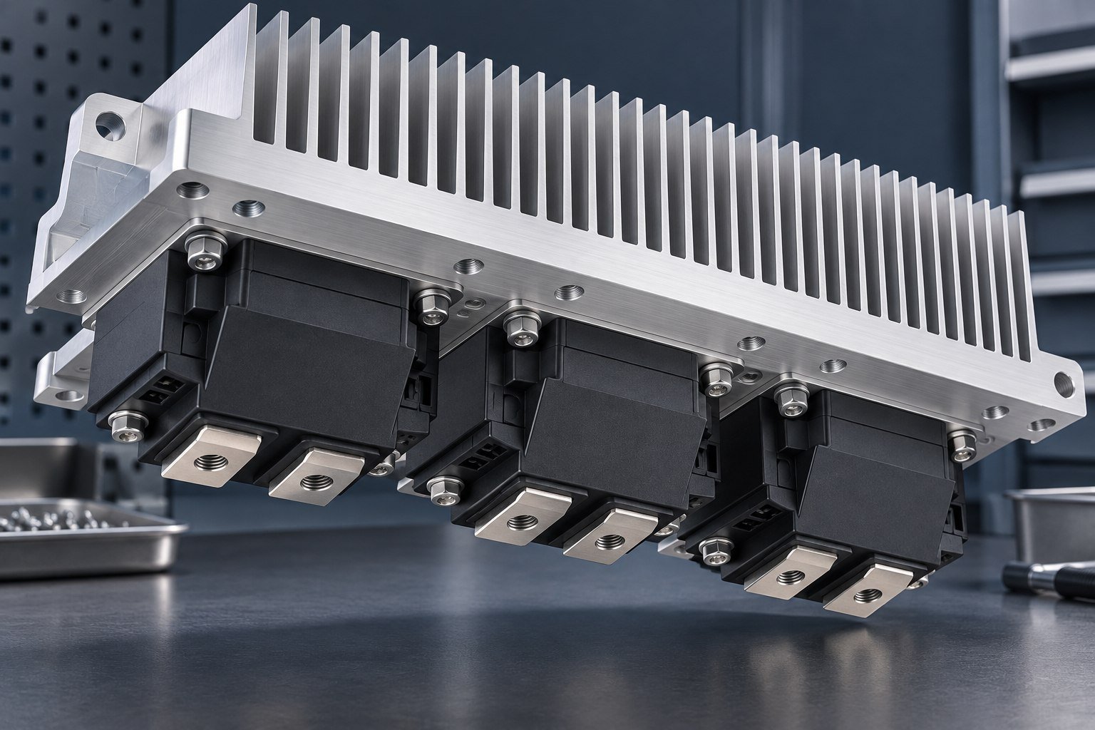
Match module footprint, insulation, clamp load and the heat-source map.
Review switching heat loads, service temperatures and mounting interfaces.
Agree operating conditions and the component acceptance scope.
Review temperature stability requirements, airflow and service access.
Review the exact device footprint, airflow path, mounting interfaces and enclosure clearance.
Identify instrument clearances, heat loads and service access.
Define contact layout, airflow conditions and the agreed validation scope.
Match the enclosure interfaces, airflow openings and maintenance plan.
Illustrative assembly and application review topics; no customer case study, system certification or universal fit claim. Explore application requirements →
Ask your quote to separate component manufacturing, joining, finishing, inspection and any independently agreed validation. The drawing review confirms availability, quantities and delivery scope.
Agree the method before the sample: joint preparation and process records, visual criteria and any specified mechanical or section checks. Define sample quantities and limits. Do not treat a clean-looking joint as proof of bond strength.
It is a design option to review, not an automatic substitution. Check the joining method, thermal expansion, service temperature, environment and corrosion protection with your assembly.
State temperature limits, dwell and transition conditions, cycle count, restraint, inspection intervals and acceptance criteria. Agree whether joint, dimensional and thermal checks are needed before and after cycling.
Here, adhesive bonding means a polymer-based joint; brazing uses a lower-melting filler metal to form a metallurgical joint. The joint temperature capability and qualification depend on the actual materials and process, so specify the route explicitly.
Send the fin and base drawing, joining requirements, material grades, operating conditions, critical fits and quantities. Ask for prototype and repeat-supply scope to be identified separately.
No. Joint resistance is one part of the path. Contact interfaces, base spreading, fin geometry and installed airflow also affect the result. Compare the complete assembly under the same test conditions.