

Injection Molding
Tooling and molding for your repeat plastic parts.
From prototype to production, coordinated manufacturing solutions for your custom parts.
View All Services →
Precision parts for your tight tolerances and complex geometry.
Tooling and molding for your repeat plastic parts.

Metal casting options for your part and production volume.

Cutting, forming and welding for your fabricated parts.

Custom profiles for your section, length and finish requirements.

Finishes for your appearance, corrosion and wear requirements.

Sub-assemblies and final builds for your production program.

Production tooling built around your process and volume.

Prototype parts to check fit, function and design.
DFM, process planning and production support for your project.
Inspection, documentation, inventory and delivery planning for your program.
Choose air- or liquid-cooling components around your thermal and mechanical requirements.

Manufacturing support for your cold plates, manifolds and cooling assemblies.

Find components for your power electronics, energy, laser and telecom application.

Components for your electronic systems.
Start with your functional and quality requirements.
Build around your operating environment.
From prototype to production, review material performance, manufacturability and cost for your part.
Review grade, temper and finish for your metal parts.
 AluminumStrength, weight and machining›
 Stainless SteelCorrosion and finish requirements›
 Carbon & Alloy SteelDiscuss grade and heat treatment›
 Tool SteelDiscuss tooling and wear needs›
 TitaniumReview grade and part geometry›
 Copper & BrassDiscuss conductivity and machining›
Match your polymer to function, process and environment.
 ABSReview enclosure and molding needs›
 Polycarbonate (PC)Discuss clarity and impact needs›
 Nylon (PA)Review moisture and wear conditions›
 POM / AcetalReview fit and sliding features›
 PEEKDiscuss operating conditions›
 PTFEReview friction and chemical exposure›
 ULTEM / PEIDiscuss thermal and electrical needs›
Confirm grade availability and application requirements.
 Silicone / LSRDiscuss flexible component needs›
 TPU / TPEReview flexibility and processing›
 EPDMReview weathering and chemical exposure.›
 NBRReview oil and fuel exposure.›
 FKMReview temperature and chemical exposure.›
 G10 / FR4Review insulation and laminate needs›
 CompositesReview stiffness, weight and laminate.›Customer-Specified MaterialsConfirm your grade and requirements.›Other Specialty MaterialsDiscuss your application and grade.›
Practical guidance for your part geometry and material decisions.
Prepare your process, budget and sourcing questions.
Build your knowledge before production.
Learn who we are and how we operate.
Find our U.S. support team or start a conversation.
CUSTOM METAL STAMPING SERVICES
Build your tooling plan around the part you need to deliver.
Connect your geometry, material and annual demand to a reviewed stamping process. Plan critical features, finishing and inspection before committing to production tooling.

METAL STAMPING OVERVIEW
For your custom sheet metal stamping, compare tooling, material utilization and the forming route around your finished part and release plan.
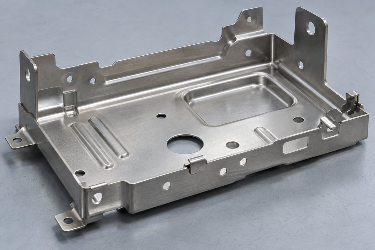
CHOOSE THE STAMPING PROCESS FOR YOUR PART
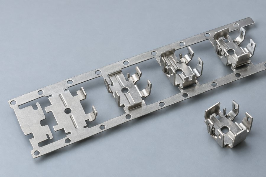
Your part stays connected to a carrier strip through successive operations. Review the strip layout, feature sequence and annual demand before investing in a dedicated tool.
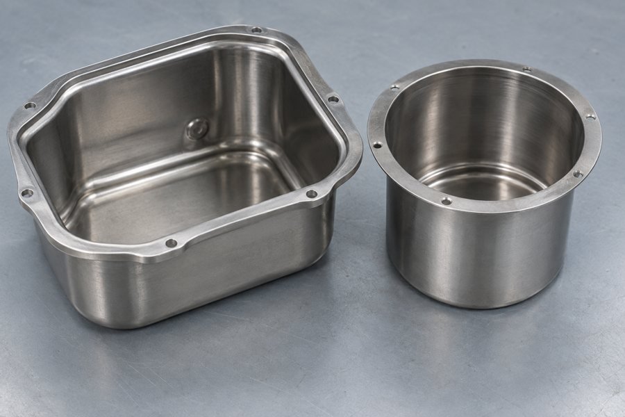
Review cup depth, corner radii and flange geometry together. Your grade, thickness and draw sequence influence thinning, wrinkling and the finishing plan.
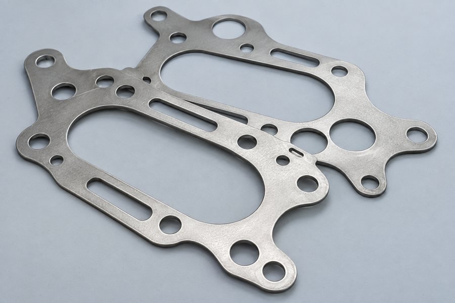
For suitable profiles, a compound die can blank and pierce in one stroke. Review flatness, hole relationships and edge requirements against the proposed tooling.
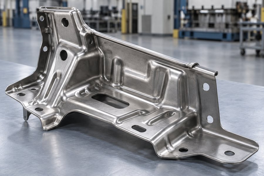
A separated workpiece moves between forming stations. Review this route for geometry that benefits from individual handling and multiple forming operations.
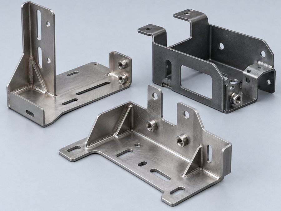
Review flexible tooling and secondary forming for your smaller release. Compare the upfront investment and unit cost with dedicated production tooling.
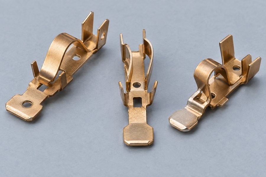
Identify functional datums, contact areas and critical tolerances early. The manufacturing and measurement plan is reviewed against your drawing and material condition.
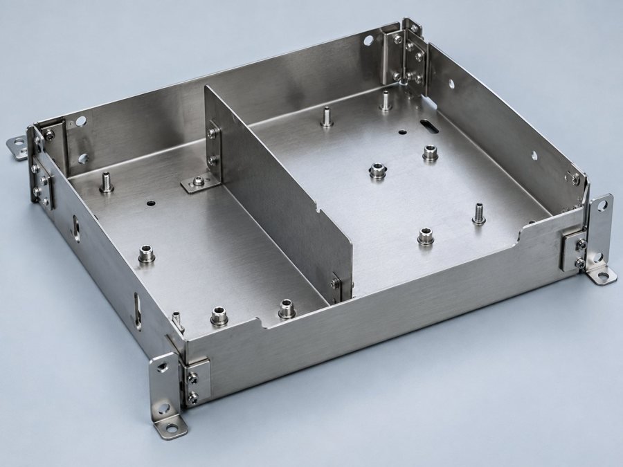
Coordinate deburring, tapping, hardware, welding and finishing with your stamped geometry. Define which operations and checks are included in your quote.
TOOLING ECONOMICS — PROTOTYPE TO REPEAT PRODUCTION
The right tooling depends on geometry, drawing stability, annual demand and tool life. Your quote should separate tooling from production cost.
For low volume metal stamping, compare setup and secondary operations with a dedicated die. Agree 4 tooling terms: ownership, storage, maintenance and revision approval.

Check fit, function and the controlled drawing before committing to dedicated dies.
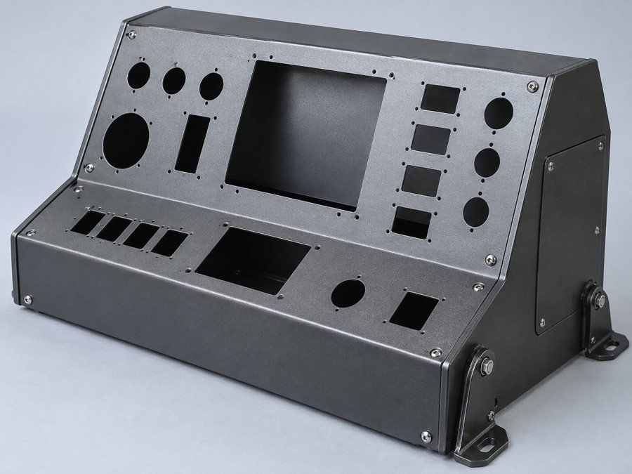
Compare flexible tools and secondary operations for your initial release and likely changes.
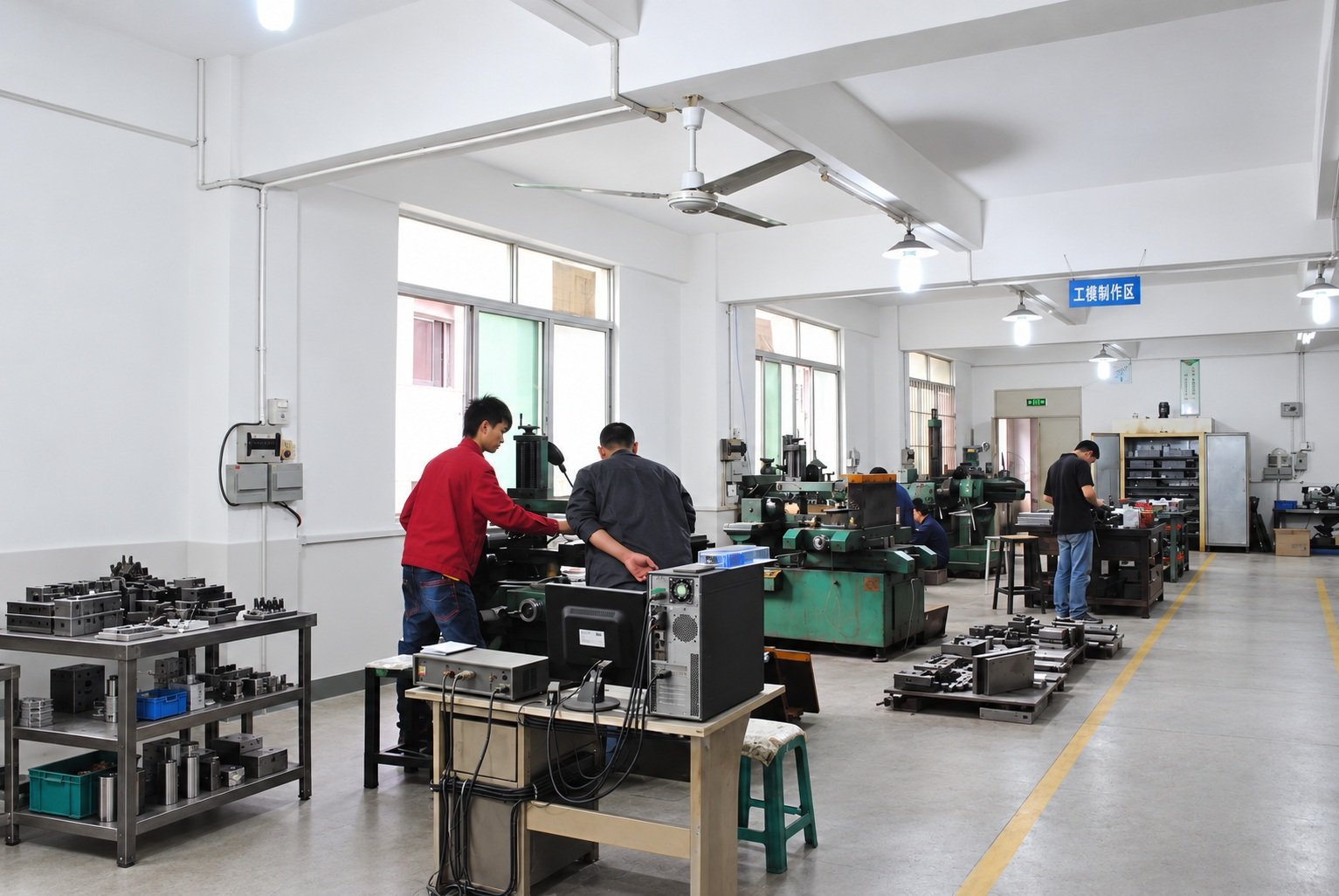
Agree die scope, sample approval, maintenance responsibilities and the inspection plan.
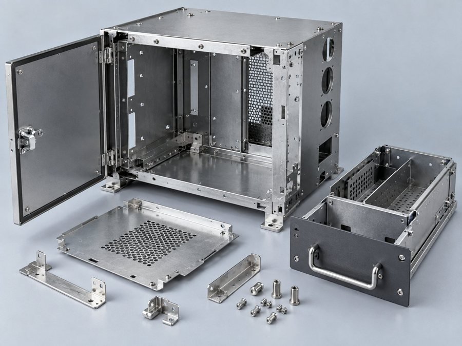
Plan release quantities, material supply, tool condition and packaging for your forecast.
STAMPING DFM — BEFORE THE TOOLING STARTS
Use these sheet metal stamping design guidelines to identify holes, bends, grain direction, burr limits and final datums before die release.
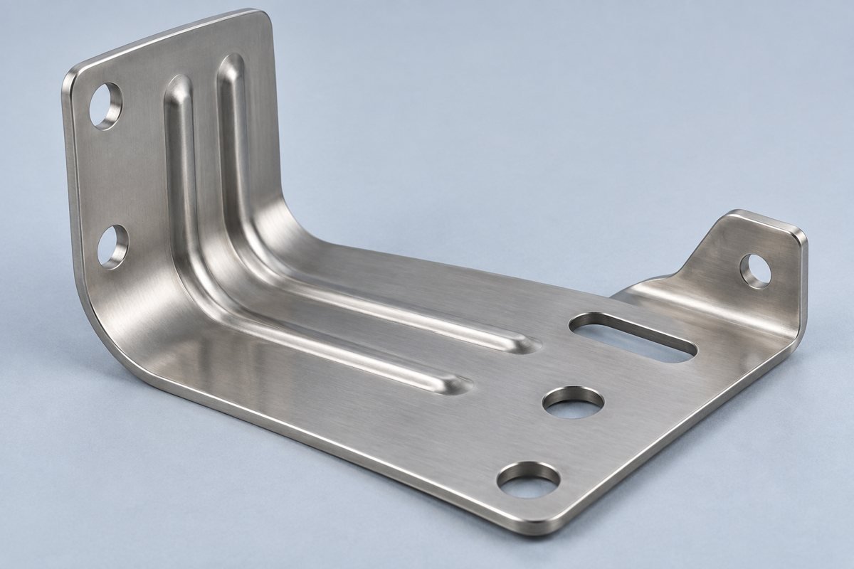
Review inside radius, grade, temper and thickness together. A suitable transition reduces forming risk and helps your part meet its assembly requirements.
Inside radius and sheet thickness • Formability and tool access • Bend location relative to features
Reduce avoidable cracking and revisions.
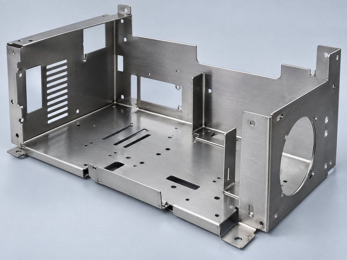
Review holes close to bends and cut edges before tooling. The required spacing depends on your material and forming sequence.
Hole-to-bend distance • Edge strength and distortion • When to pierce the feature
Protect fastener alignment and assembly fit.
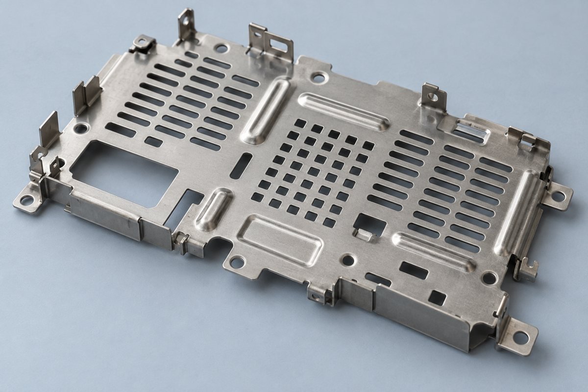
Review the metal left between slots and holes. Narrow webs influence tool strength, distortion and consistent part handling.
Feature spacing and support • Punch strength and die clearance • Scrap and slug removal
Reduce damaged features and production interruptions.
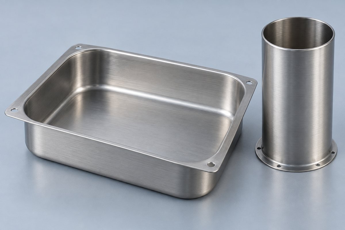
Discuss draw depth, corner transitions and any redraw stages. Feasibility is reviewed for the actual blank geometry, grade and thickness.
Blank size and draw sequence • Thinning and wrinkling risk • Trim and cosmetic requirements
Avoid late changes to your drawn housing.
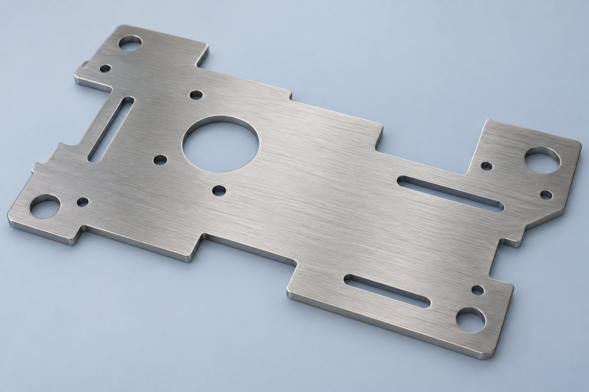
For direction-sensitive forming, identify rolling direction and review how it relates to bends and nesting. Material condition also matters.
Rolling direction and bend orientation • Grade and temper • Layout and material utilization
Improve the consistency of your formed features.
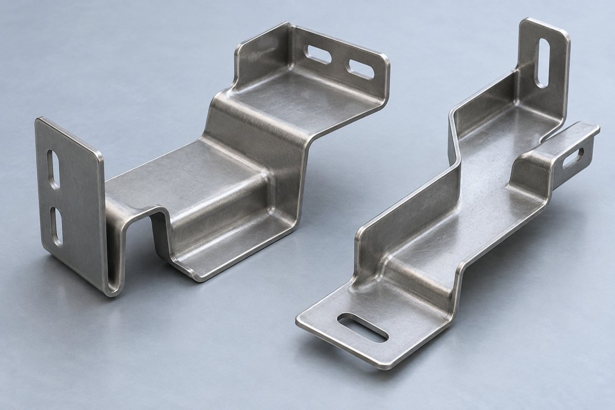
Elastic recovery varies with material, thickness and geometry. Define your final part condition and review compensation through samples.
Final angle and profile • Material lot and condition • Sample measurements and compensation
Protect your final fit and reduce adjustment.
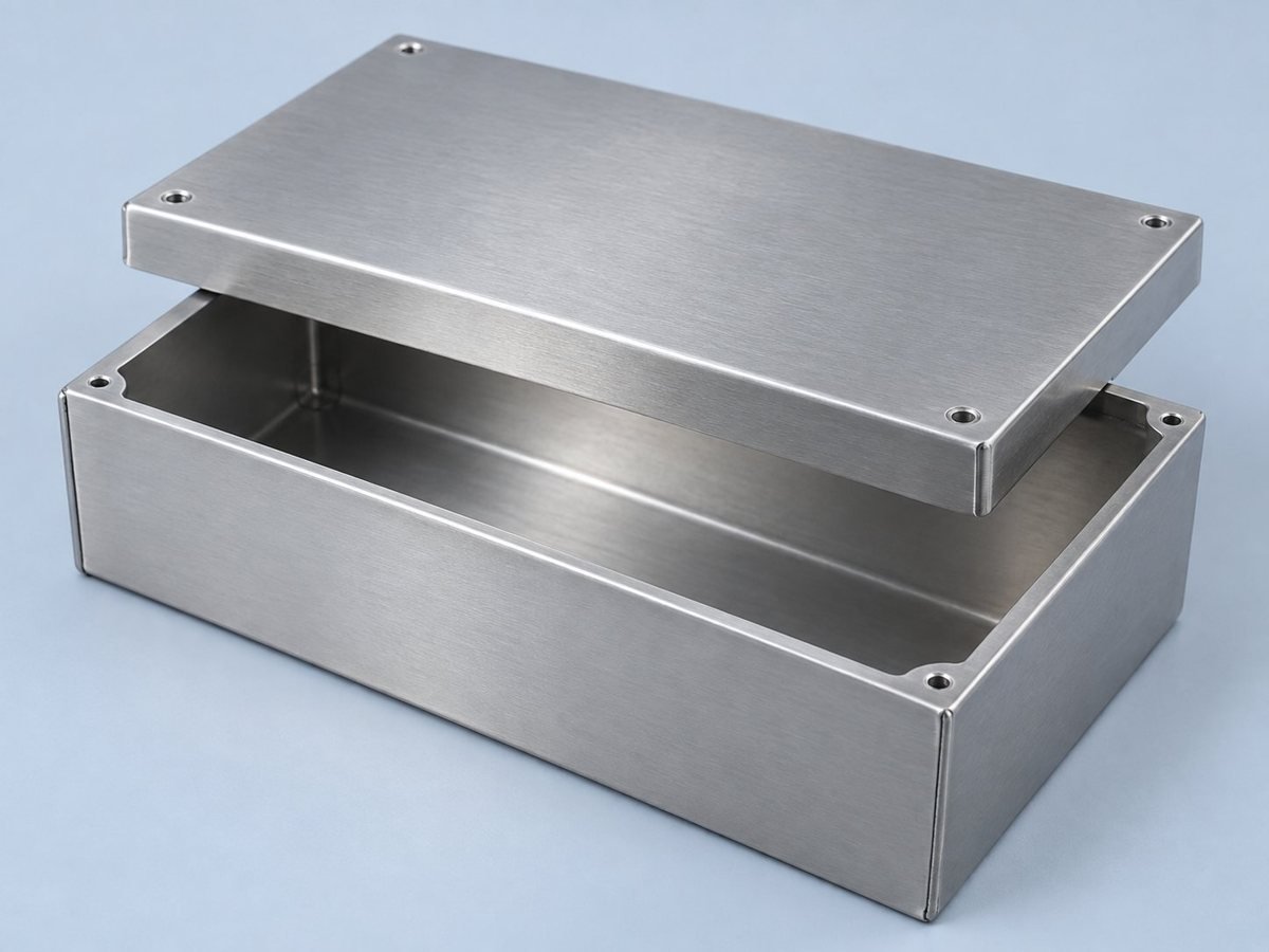
Identify the datums that locate your part in its assembly. Align tooling, inspection fixtures and the drawing to those functional references.
Functional datum scheme • Fixture and measurement access • Critical feature relationships
Make acceptance evidence relevant to your assembly.
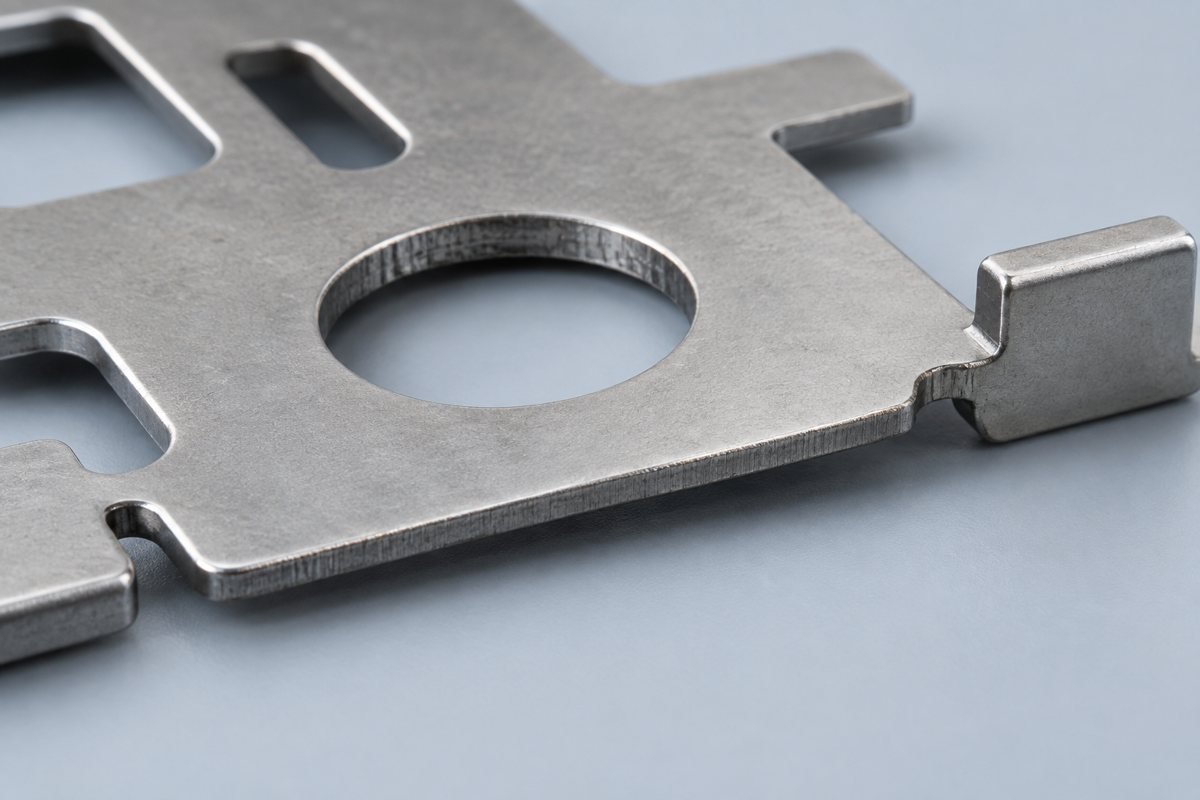
Specify burr direction, edge condition and visible surfaces. Agree deburring and cosmetic acceptance before tool design and finishing.
Burr direction and allowed edge condition • Visible zones and handling marks • Deburring and finish sequence
Reduce receiving disputes and downstream rework.
PROCESS COMPARISON
Use this as a starting point. Your final route, tolerance and schedule are confirmed after drawing review.
For metal stamping vs laser cutting, compare repeat demand, tooling investment, formed features and revision risk. Explore Laser Cutting → · Review Bending & Forming →
| Decision | Progressive Die | Deep Draw | Compound / Single-Stage | Transfer | Short Run |
|---|---|---|---|---|---|
| Best fit | Repeated multi-feature parts | Cups and drawn housings | Flat blanked / pierced profiles | Multi-stage formed parts | Early or limited releases |
| Main review | Strip layout and feature sequence | Material flow and thinning | Hole-to-profile relationships | Handling and station sequence | Flexible tooling and extra handling |
| Tooling approach | Dedicated multi-station die | Draw tools and possible redraws | Part-specific operation tooling | Multiple forming stations | Simpler or modular tooling |
| Cost focus | Annual demand and material yield | Number of forming stages | Tool complexity and run size | Tooling plus transfer operations | Lower commitment versus unit cost |
| Your approval | Stable drawing and trial samples | Drawn sample and wall condition | Feature inspection and edges | Formed sample and datums | Fit validation and next release |
MATERIALS & FINISHES FOR YOUR APPLICATION
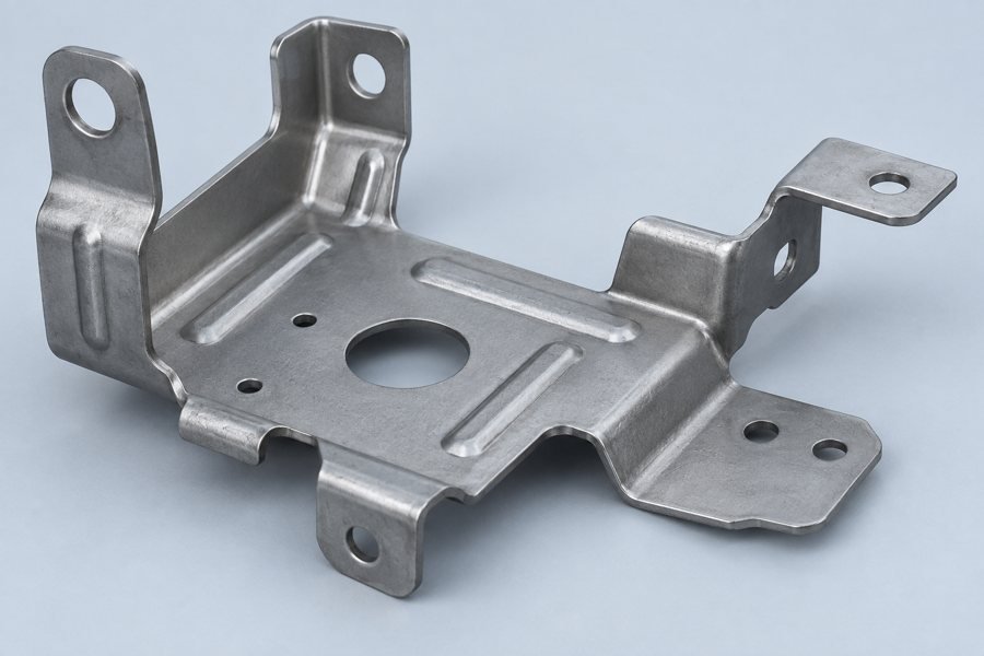
Review formability, strength and your corrosion-protection plan.
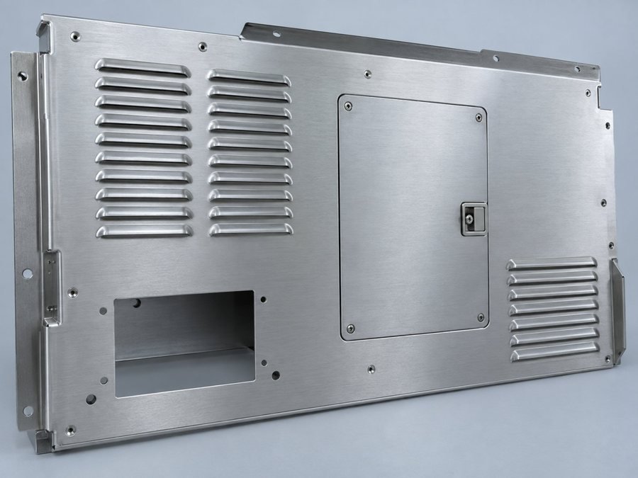
Review grade, work hardening, springback and cosmetic finish.
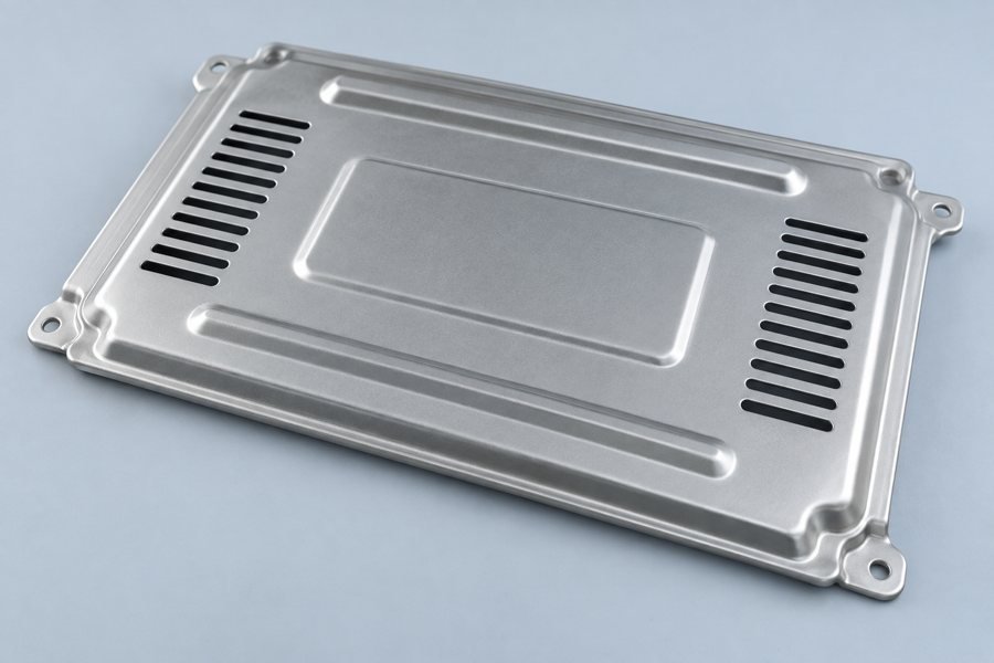
Match alloy and temper to forming, weight and finish requirements.
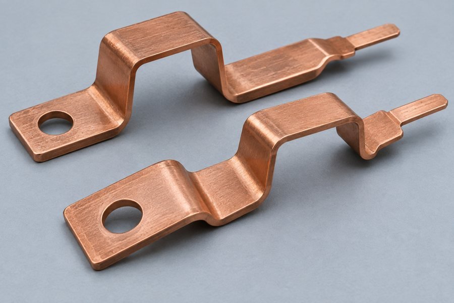
Review conductivity, contact geometry and surface protection.
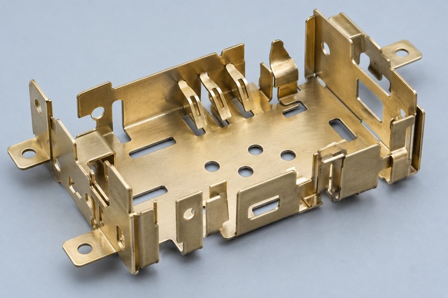
Balance formability, contact performance and required plating.
Finish compatibility and acceptance are reviewed for your selected material. Explore surface finishing →
FROM COIL OR SHEET TO YOUR FINISHED PART
Start with the approved material grade, thickness and lot records, then follow the agreed operation sequence.
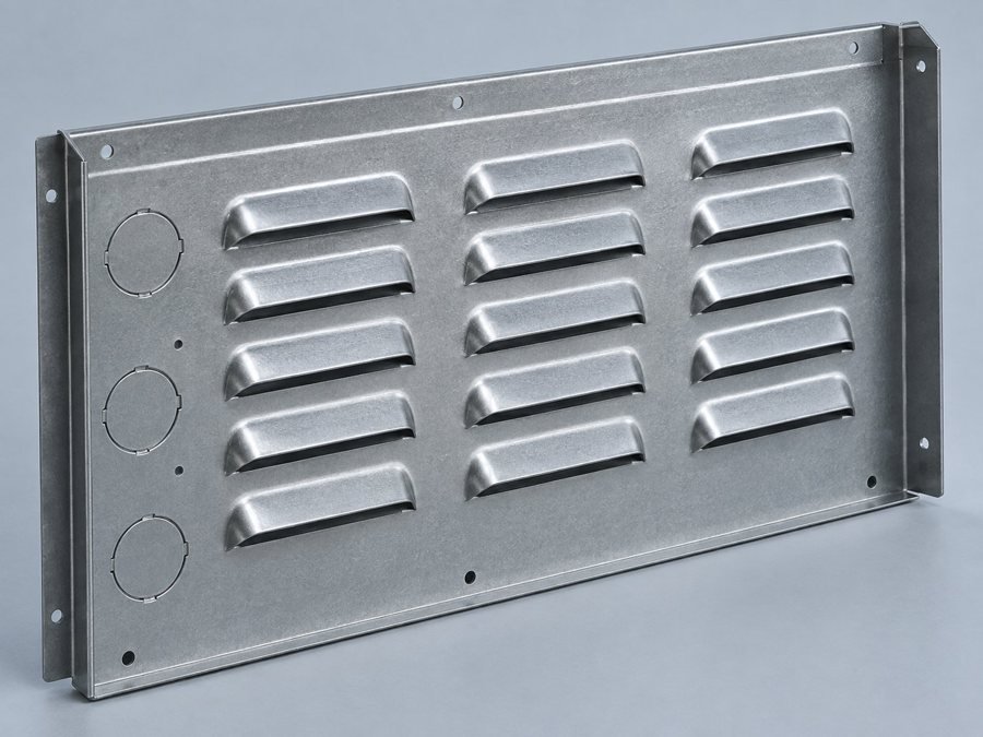
Create your profile and openings.
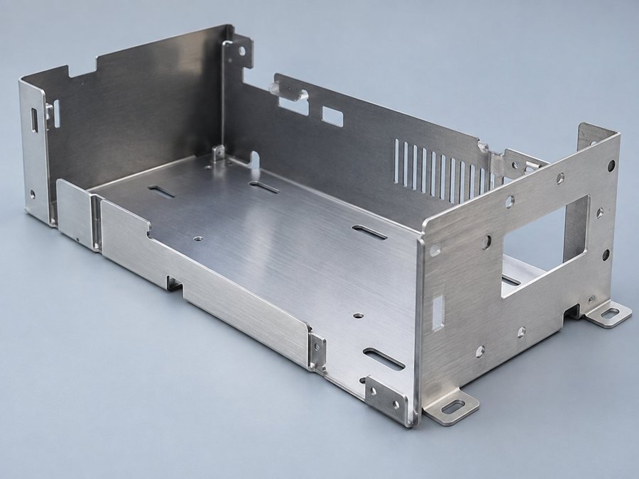
Produce your bends and shape.
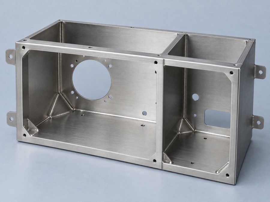
Join or add agreed features.
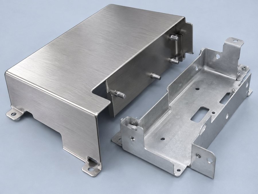
Meet your finish specification.
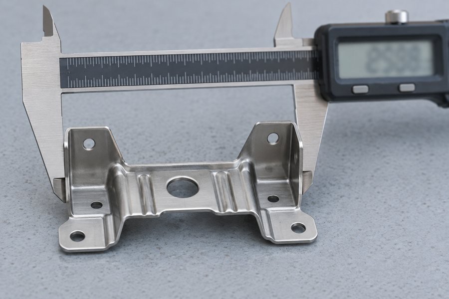
Verify your agreed requirements.
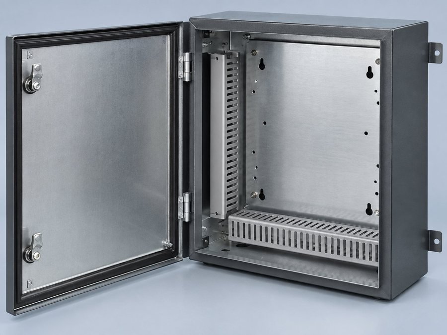
Protect and identify your release.
QUALITY YOU CAN VERIFY
Define the evidence your receiving and assembly teams need before production begins. Agree metal stamping tolerances by feature, datum and inspection state, including any coating allowance.
Check your agreed critical dimensions.
Review sample reports before release.
Match the method to your features.
Agree scope before quotation.
Request the required available records.
Plan checks for your repeat supply.
Use your agreed edge and finish criteria.
Connect the part to its release records.
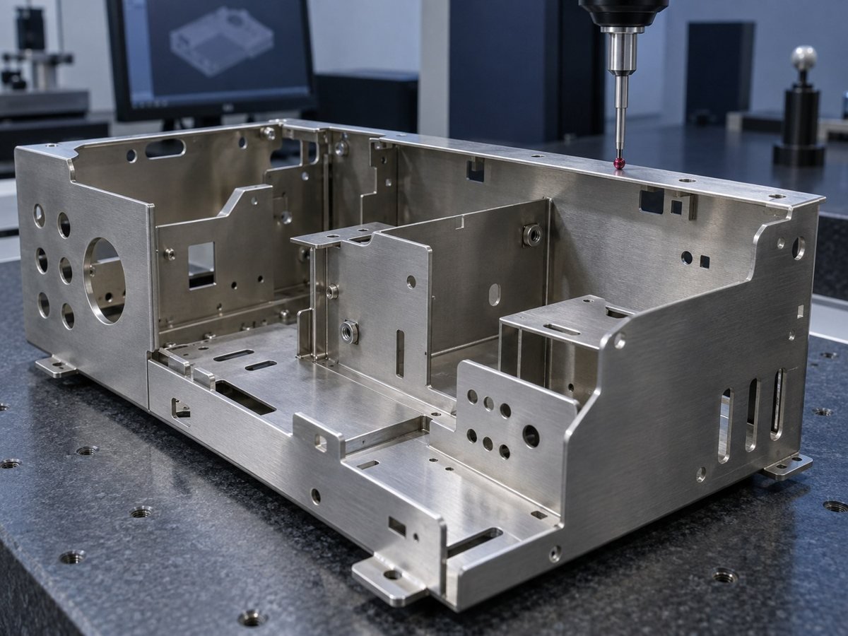
INDUSTRIES & APPLICATIONS
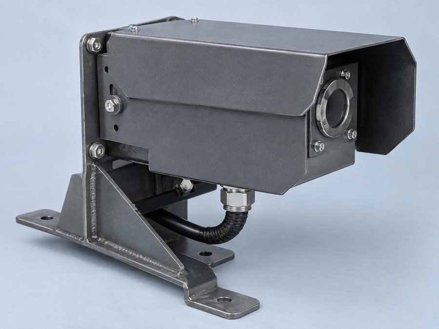
Your mounting and formed structural interfaces.
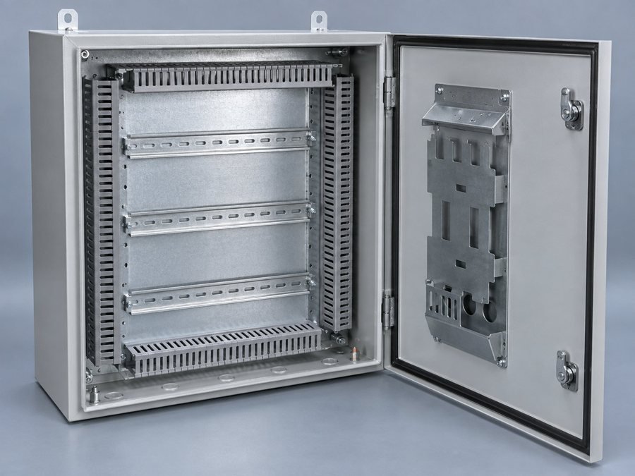
Your shielding, mounting and contact requirements.
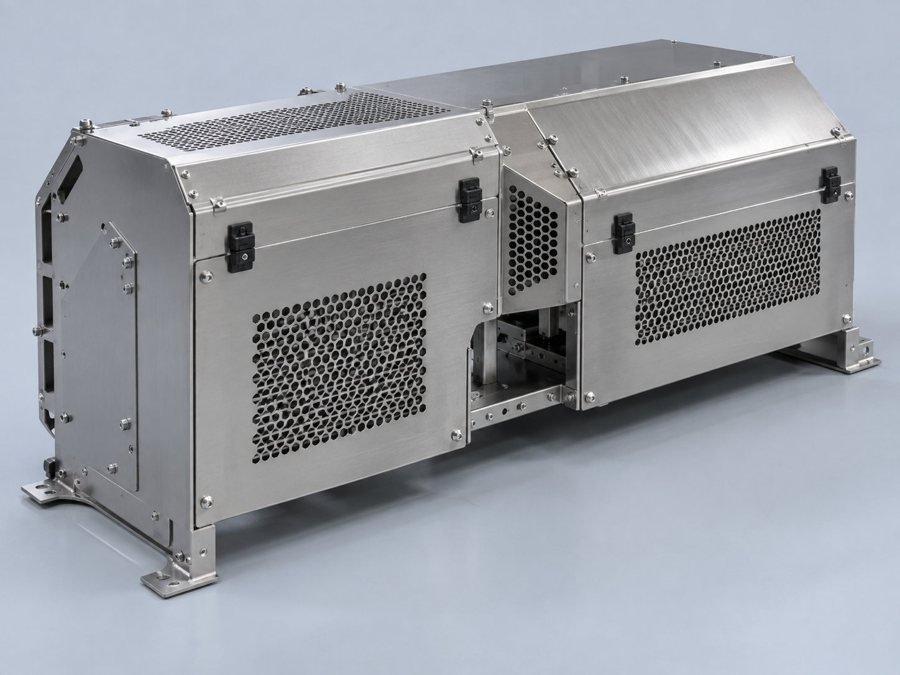
Your brackets, covers and formed supports.

Your controlled drawing and inspection scope.
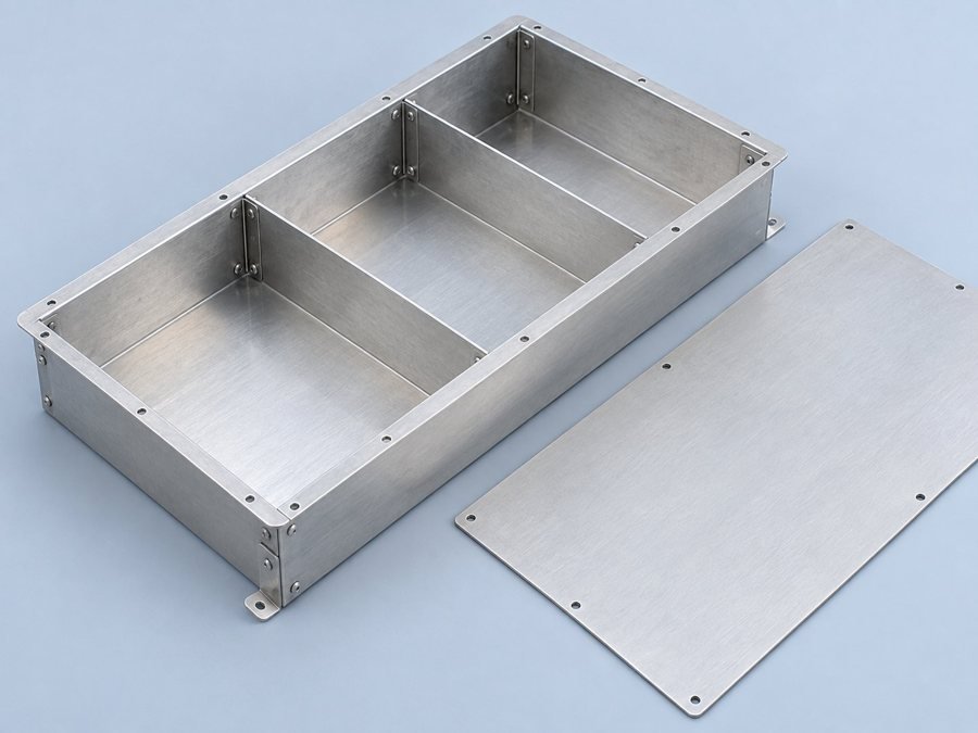
Your enclosure and power-system interfaces.
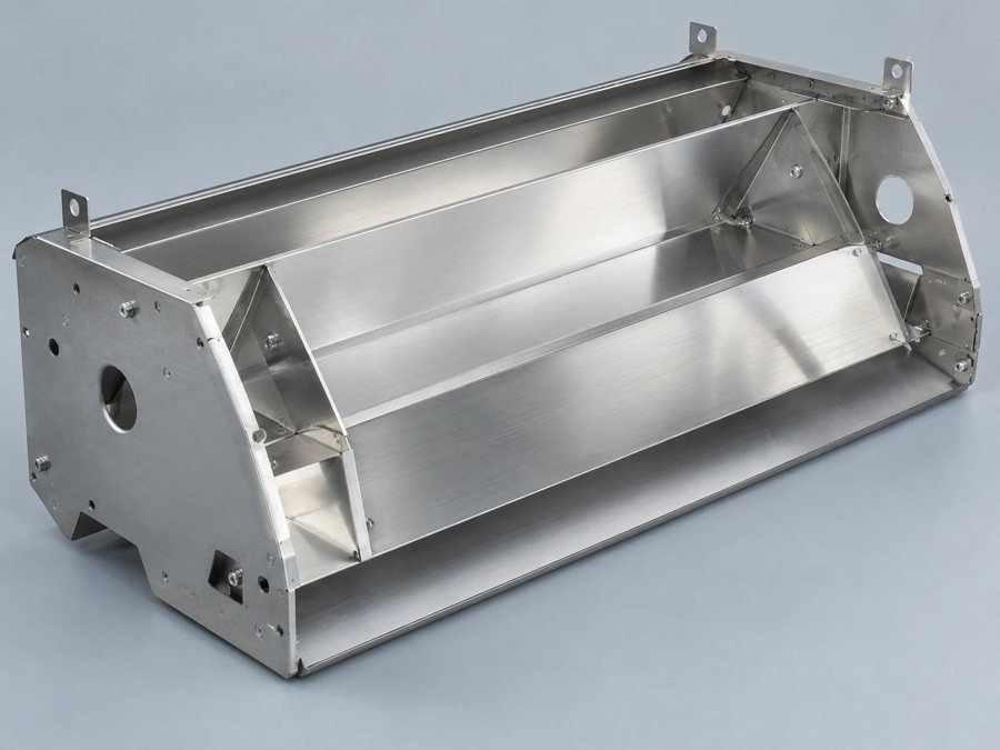
Your housings, reflectors and mounting details.
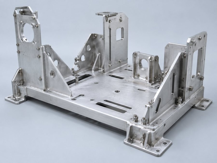
Your repeatable mounting and assembly features.
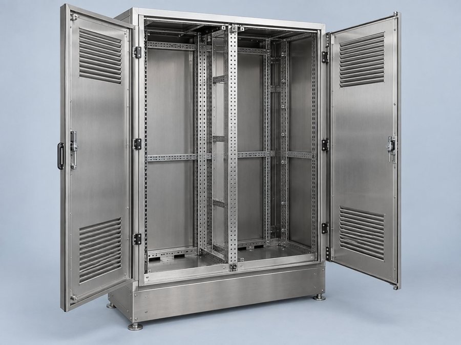
Your covers, brackets and cosmetic criteria.
LOCAL SUPPORT. GLOBAL MANUFACTURING.

Request a metal stamping tooling transfer review before moving the tool. Share die drawings, dimensions, press requirements, condition, maintenance history and accepted samples. Compatibility, repair scope and revalidation must be agreed before repeat supply.
Compare 6 items on the same drawing revision: material and yield, tooling, setup, stamping operations, finishing, and inspection with delivery. Separate one-time tooling from recurring unit cost and use your actual release quantities.
Your economical order quantity depends on tooling complexity, material, setup and repeat demand. Send your initial quantity and annual forecast so flexible tooling and dedicated dies can be compared.
Discuss carbon steel, stainless steel, aluminum, copper or brass with the exact grade, temper and thickness. Feasibility depends on geometry, forming depth and your final requirements.
Your quotation should identify tooling charges, included trials, maintenance responsibilities, storage and ownership terms. Review these items before authorizing the tool.
Tool design and manufacture, material availability, sampling, revisions, finishing and inspection all affect the schedule. Your reviewed quotation confirms the planned lead time.
We review forming geometry, hole spacing, datums, burr direction and the proposed operation sequence. Your team approves any design changes and the controlled revision.
Share the required report format, submission level and inspection scope before quoting. Included documentation and approval steps are agreed for your program.
Include plating or coating, masking, hardware, welding, assembly and packaging requirements with your drawing. We review the complete operation scope and acceptance criteria.
Confirm your drawing, tooling scope and sample acceptance.
Confirm the approved revision, forecast and delivery scope.
Product visuals illustrate manufacturing concepts, not customer case studies. Your approved drawings and agreed specifications control supplied parts.
Discuss Your Project




