

Injection Molding
Tooling and molding for your repeat plastic parts.
From prototype to production, coordinated manufacturing solutions for your custom parts.
View All Services →
Precision parts for your tight tolerances and complex geometry.
Tooling and molding for your repeat plastic parts.

Metal casting options for your part and production volume.

Cutting, forming and welding for your fabricated parts.

Custom profiles for your section, length and finish requirements.

Finishes for your appearance, corrosion and wear requirements.

Sub-assemblies and final builds for your production program.

Production tooling built around your process and volume.

Prototype parts to check fit, function and design.
DFM, process planning and production support for your project.
Inspection, documentation, inventory and delivery planning for your program.
Choose air- or liquid-cooling components around your thermal and mechanical requirements.

Manufacturing support for your cold plates, manifolds and cooling assemblies.

Find components for your power electronics, energy, laser and telecom application.

Components for your electronic systems.
Start with your functional and quality requirements.
Build around your operating environment.
From prototype to production, review material performance, manufacturability and cost for your part.
Review grade, temper and finish for your metal parts.
 AluminumStrength, weight and machining›
 Stainless SteelCorrosion and finish requirements›
 Carbon & Alloy SteelDiscuss grade and heat treatment›
 Tool SteelDiscuss tooling and wear needs›
 TitaniumReview grade and part geometry›
 Copper & BrassDiscuss conductivity and machining›
Match your polymer to function, process and environment.
 ABSReview enclosure and molding needs›
 Polycarbonate (PC)Discuss clarity and impact needs›
 Nylon (PA)Review moisture and wear conditions›
 POM / AcetalReview fit and sliding features›
 PEEKDiscuss operating conditions›
 PTFEReview friction and chemical exposure›
 ULTEM / PEIDiscuss thermal and electrical needs›
Confirm grade availability and application requirements.
 Silicone / LSRDiscuss flexible component needs›
 TPU / TPEReview flexibility and processing›
 EPDMReview weathering and chemical exposure.›
 NBRReview oil and fuel exposure.›
 FKMReview temperature and chemical exposure.›
 G10 / FR4Review insulation and laminate needs›
 CompositesReview stiffness, weight and laminate.›Customer-Specified MaterialsConfirm your grade and requirements.›Other Specialty MaterialsDiscuss your application and grade.›
Practical guidance for your part geometry and material decisions.
Prepare your process, budget and sourcing questions.
Build your knowledge before production.
Learn who we are and how we operate.
Find our U.S. support team or start a conversation.
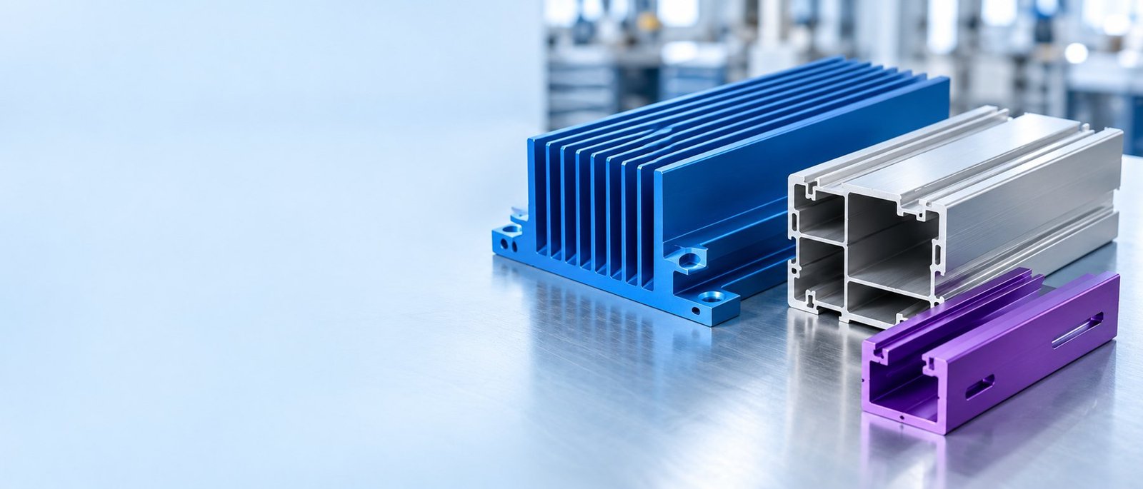
FOR YOUR PROFILE, FINISH AND FINAL FIT
For your 6063 aluminum CNC machining project, connect the profile, T5/T6 condition and finished features before ordering. Review your section drawing, secondary machining and appearance as one part specification.
Existing profile or a new extrusion die?
Confirm the temper and product specification.
Separate extruded and machined dimensions.
Define color, masking and final fits.
Agree material and inspection records.
YOUR MATERIAL DECISION
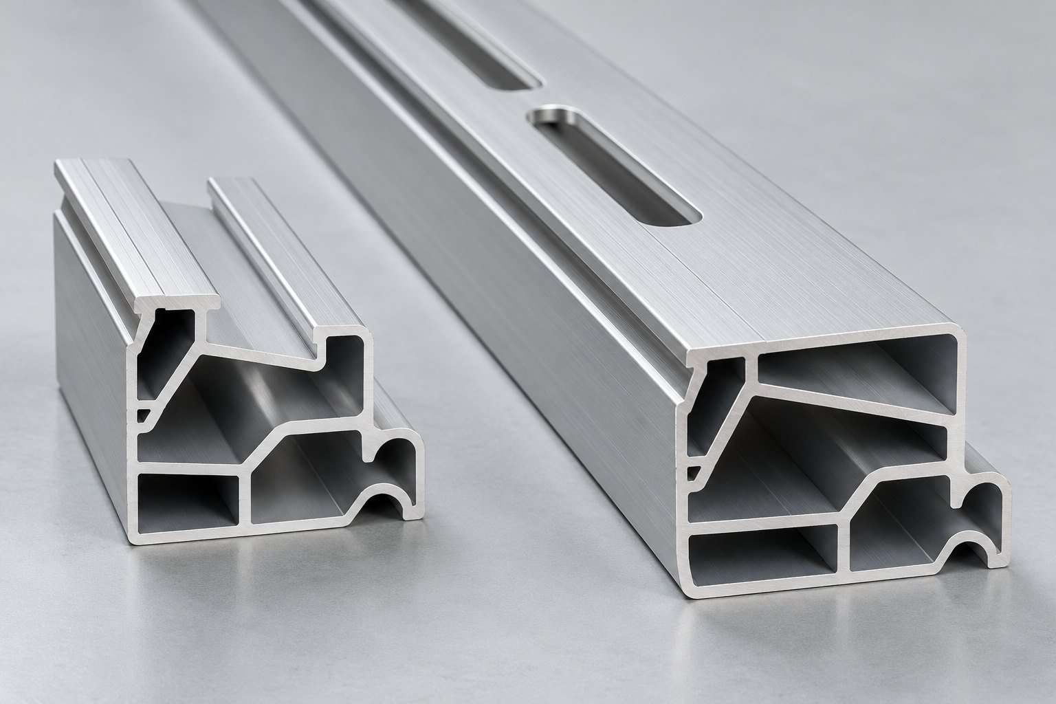
For custom 6063 aluminum parts, start with the section your assembly needs. 6063 is a candidate for hollow profiles, visible housings and finned sections where extrusion and finishing matter together.
Your load, wall layout, straightness, mating features and environment still control the choice. A material name does not define a finished-part tolerance or thermal result.
Review die feasibility and cut length.
Locate bores, slots and end faces.
Agree visible faces and packaging.
COMPOSITION + CONDITION
Keep composition, temper and the applicable product standard on the same purchase order.
Cooled after an elevated-temperature shaping process and artificially aged. For 6063-T5 aluminum parts, confirm the supplied section and its material record.
Solution heat-treated and artificially aged. For 6063-T6 aluminum parts, define the required final condition, including effects of later welding or heat.
| Element | Weight % | Element | Weight % |
|---|---|---|---|
| Silicon (Si) | 0.20–0.60 | Magnesium (Mg) | 0.45–0.90 |
| Iron (Fe) | ≤0.35 | Copper (Cu) | ≤0.10 |
| Manganese (Mn) | ≤0.10 | Chromium (Cr) | ≤0.10 |
| Zinc (Zn) | ≤0.10 | Titanium (Ti) | ≤0.10 |
| Other: each | ≤0.05 | Other: total | ≤0.15 |
| Aluminum (Al) | Remainder | Basis | Maximum unless a range is shown |
Weight percentages. “Remainder” identifies the aluminum balance; it is not a separate purity guarantee. Confirm the applicable material specification and lot certificate.
| Condition / test-section thickness | UTS min. | 0.2% yield min. | Elongation min. |
|---|---|---|---|
| T5, ≤12.50 mm | 150 MPa | 110 MPa | 8% |
| T6, ≤3.20 mm | 205 MPa | 170 MPa | 8% |
These are source minimum levels for the listed test-section ranges, not universal typical values. Test-section thickness determines the applicable limits. Elongation is in 2 inches or 4× specimen diameter; the source exempts some small/thin shapes from elongation testing.
| Property / condition | Reference value |
|---|---|
| Typical thermal conductivity, 25 °C — T5 / T6 | 209 / 201 W/(m·K) |
| Typical electrical conductivity, 20 °C — T5 / T6 | 55 / 53% IACS |
| Density | 0.097 lb/in³ |
| Melting range | 1140–1210 °F |
| Average linear thermal expansion, 68–212 °F | 13.0 × 10⁻⁶ in/(in·°F) |
Conductivity values are typical, not a heat-sink rating or finished-part guarantee. Temperature, geometry and test conditions matter.
Sources: Hydro Alloy 6063 data, Rev. 2026/01 (06/2026); AEC temper definitions. Different limits apply to other thicknesses and conditions. Neither table authorizes an unapproved T5/T6 substitution.
Supply the profile cross section, length and current drawing revision.
Identify an existing extrusion, customer-supplied stock or a new die.
Agree 6063, temper, product form and required material document.
Define datums, clamping, holes, slots, end faces and burr limits.
Check dimensions in the specified finish state and appearance sample.
Keep the approved revision, finish reference and change record.
Use the topic that controls your assembly. These review checks are tailored to your drawing.
Use stable assembly references for 6063 aluminum secondary machining. Distinguish an extruded face from a machined datum and agree how the part is supported.
For 6063 aluminum profile milling, review wall stiffness, clamp pressure and cutter reach before freezing the geometry.
Cut length, straightness and twist can affect fixture seating even when a local hole is correctly machined.
Review long slots, internal corner radii and access through a hollow section.
Specify thread depth, engagement and breakout where a hole intersects a hollow profile.
A 6063 aluminum heat sink needs the contact geometry and operating conditions, as well as a material selection.
Identify exposed faces before choosing clamps, rack contacts, marks or packing materials.
Coating, sealing and masking belong in the same dimensional decision as the machined feature.
SURFACE + ASSEMBLY
Resolve appearance and fits together, before your parts are processed.
Specify the type, color reference, thickness and sealing with your appearance and dimensional requirements. Define visible faces and allowable racking marks.
Illustrative finish concept; color does not identify alloy or temper.
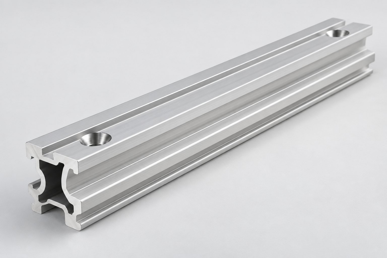
For black anodized 6063 aluminum extrusion, agree gloss, texture, color reference and masked areas. On-screen color is not your production acceptance standard.
Illustrative finish concept; color does not identify alloy or temper.
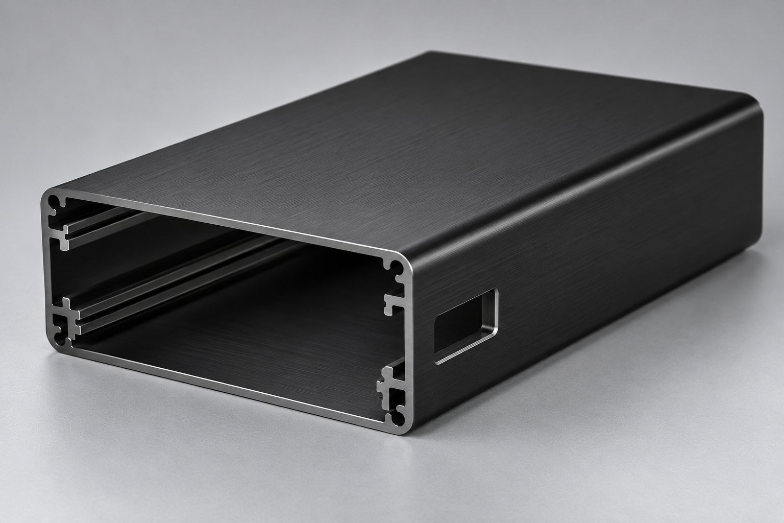
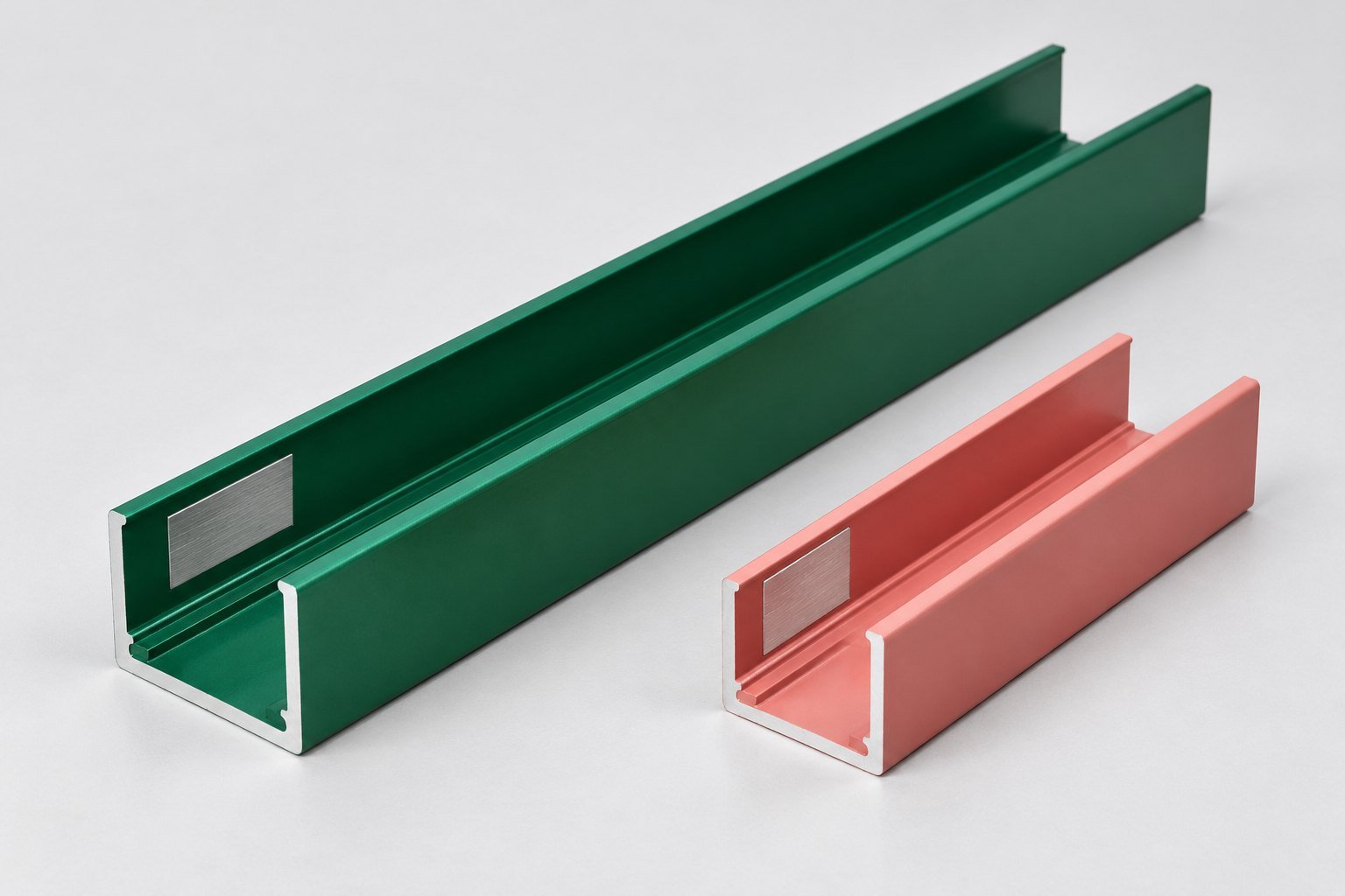
Agree color, gloss, texture and masking for powder-coated channels or covers. Review coating build at mating edges and any conductive contact areas.
Illustrative finish concept; color does not identify alloy or temper.
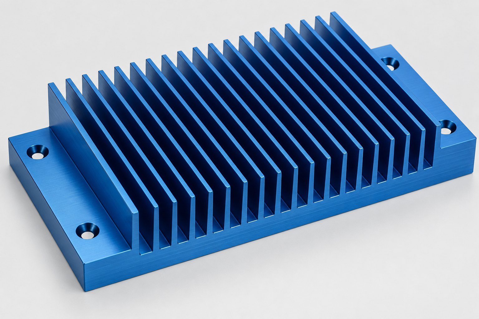
For your power-electronics profile, review fin geometry, base thickness, airflow and the thermal interface. The alloy designation alone does not establish a heat-dissipation rating.
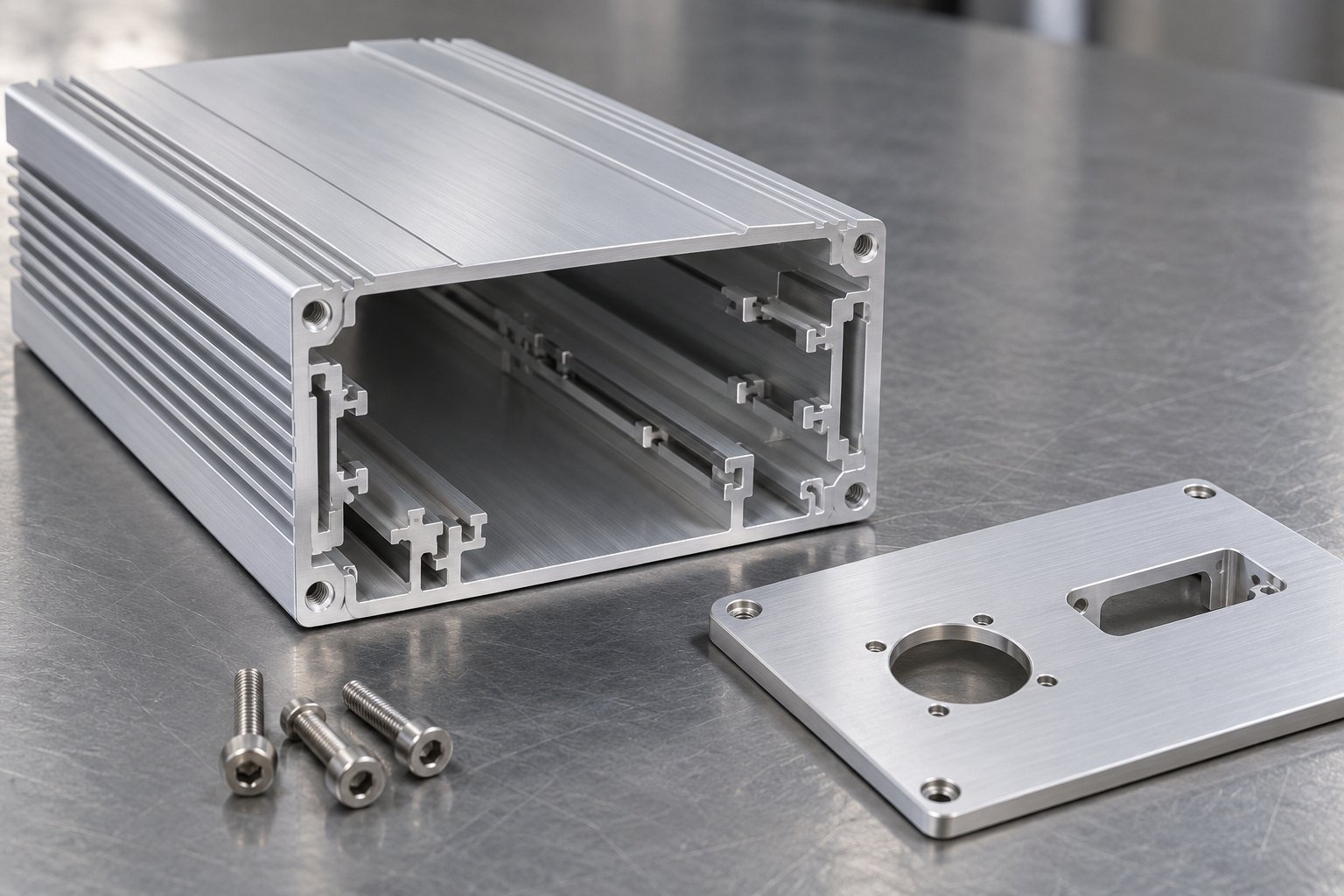
For a 6063 aluminum electronic enclosure, define board guides, connector ports, covers and mounting faces. IP, EMC or other product ratings require their own design and verification.
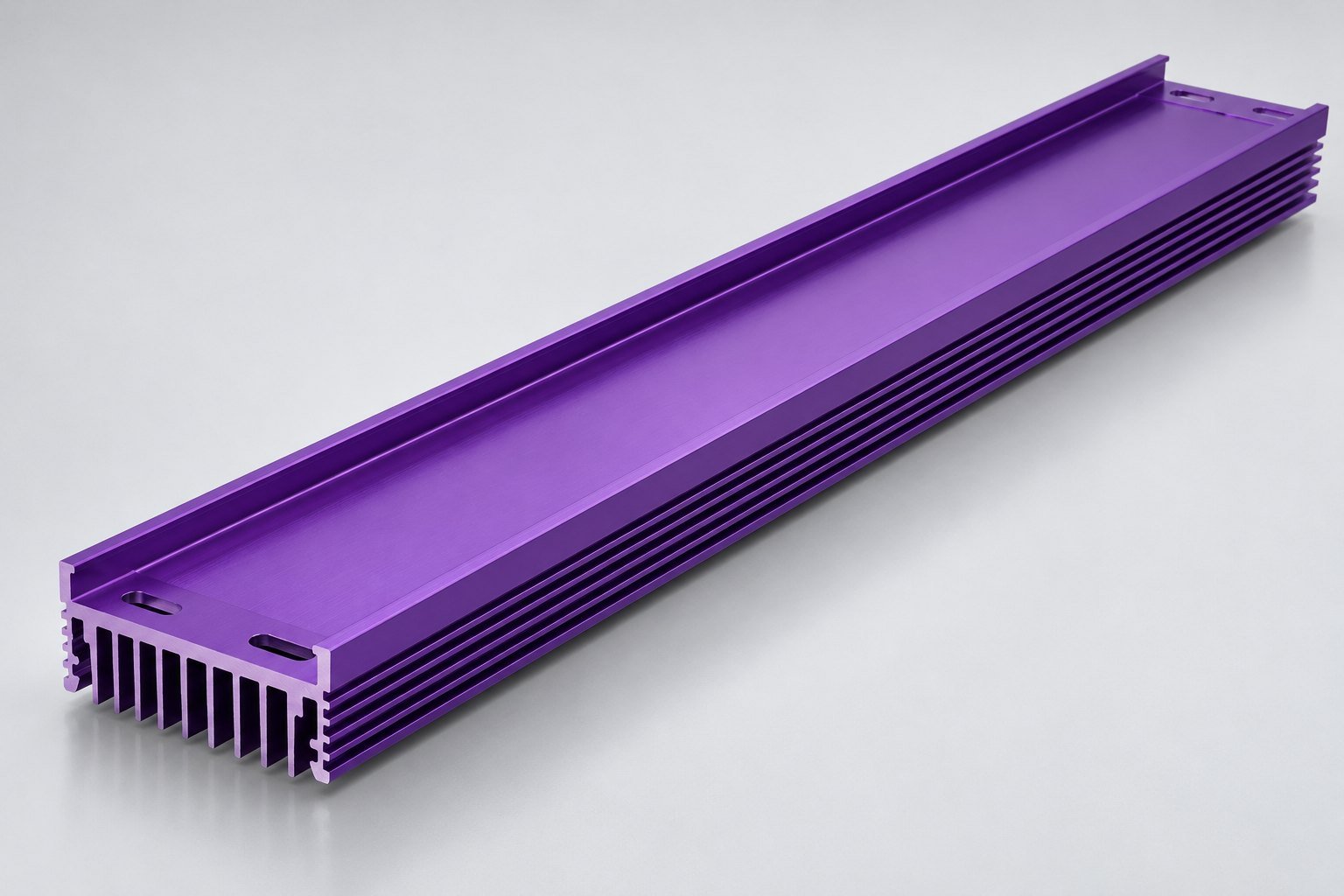
Review the LED mounting bed, installation space, cooling path and operating conditions. Mark the contact face and finish requirements before machining.
Illustrative component scenarios, not customer cases, certified assemblies or tested thermal results.
COMPARE THE SAME SUPPLIED SCOPE
For 6063 aluminum prototype machining, identify what the sample must prove and how the intended production section will be represented.
Value Engineering →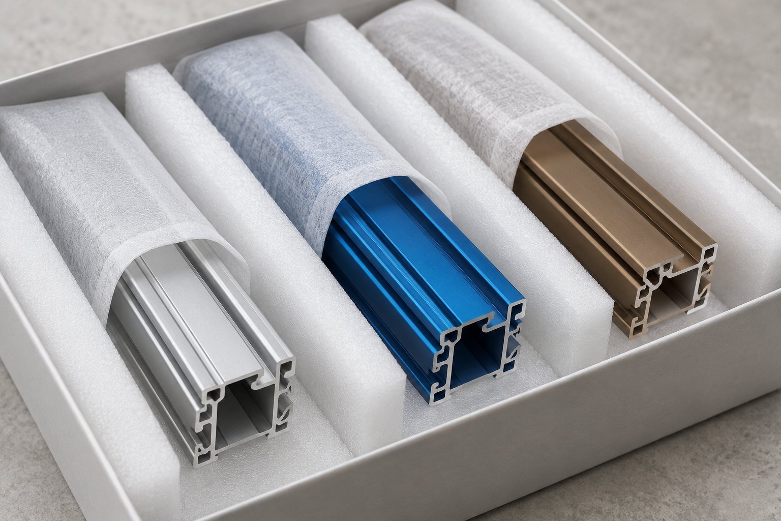
YOUR SECTION + YOUR LOCAL FEATURES
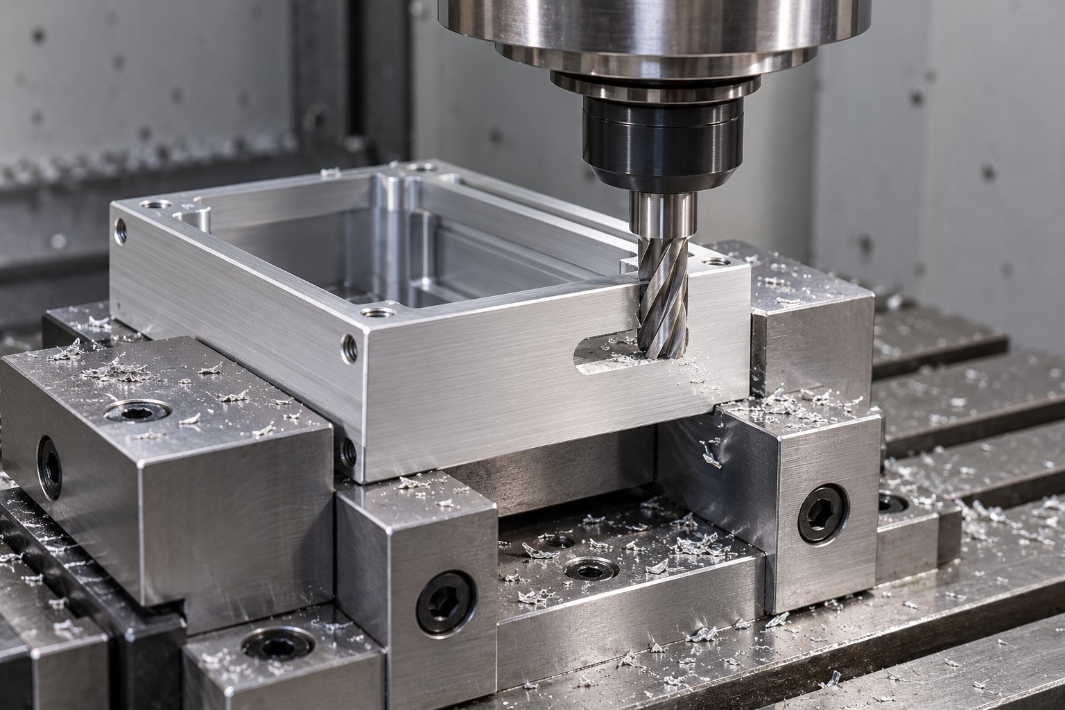
For custom 6063 aluminum extruded parts, extrusion can establish the continuous section. CNC operations then create local holes, slots, end faces and assembly interfaces.
6063 aluminum extrusion CNC machining needs a controlled relationship between the starting profile and final drawing. Distinguish cut length, raw profile variation and the finished features you will inspect.
Confirm stock condition, wall support and burr acceptance for your supplied profile.
Review the final condition, removal pattern and features that control assembly.
FOR YOUR RECEIVING TEAM
Keep identity, dimensions and appearance evidence separate and traceable.
6063, temper, product form and the applicable purchase standard.
Section dimensions, cut length, straightness or twist where specified.
Datums, holes, slots, threads and final inspection condition.
Color/texture reference, masking and required checks.
Material documents, lot linkage and dimensional report scope.
Handling, separators, identification and packing requirements.
COORDINATE YOUR OPEN DECISIONS
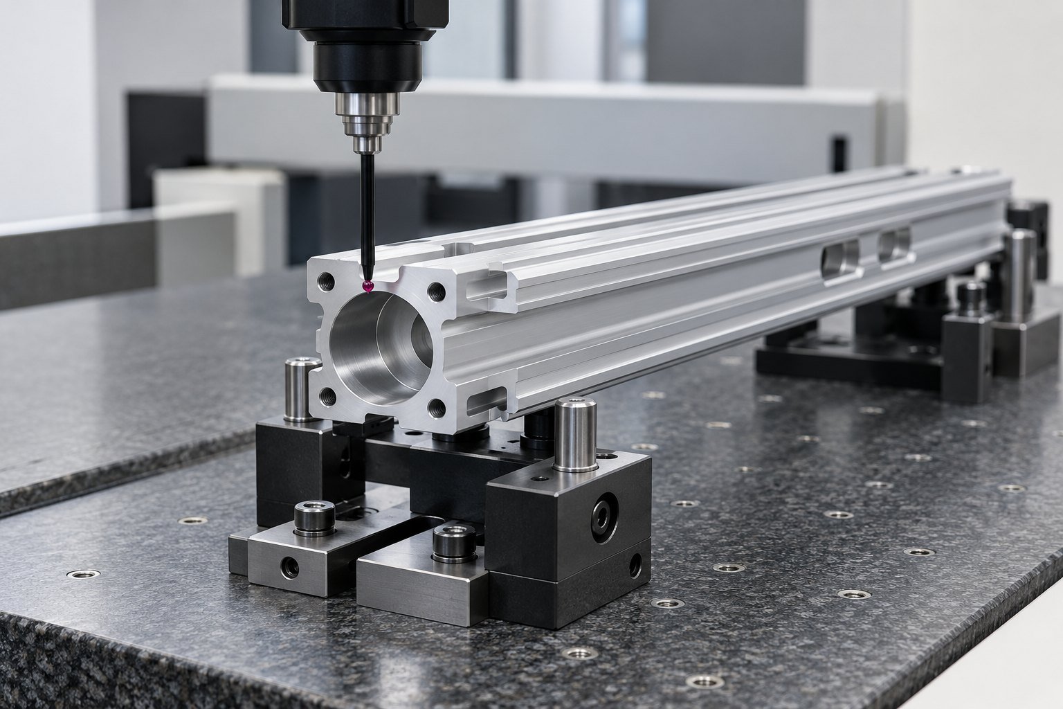
Bring your drawing, supply route and delivery requirements to the same project review. China manufacturing and Dallas-area coordination are confirmed in your quotation.
Coordinate profile questions, drawing revisions and approval decisions.
Agree extrusion, machining, finish and supplied records.
Record dimensions, appearance and accepted exceptions.
Confirm packing, delivery location and release requirements.

01Cross-section drawing, CAD and controlled finished-part revision
026063, temper, product specification and permitted alternatives
03Existing profile, customer stock or new die requirement
04Cut length, trial quantity and repeat demand
05Critical fits, datums, finish, masking and visible faces
06Inspection records, packing and delivery requirements
For 6063 aluminum machining services, identify open requirements before comparing quotations.
6063 aluminum machined parts can be reviewed for suitable pockets, slots, holes and end features. Feasibility depends on temper, section support, access, removal volume and finished tolerances. Compare the complete route with an extrusion-led or stock-machining alternative.
T5 is cooled from an elevated-temperature shaping process and artificially aged; T6 is solution heat-treated and artificially aged. Confirm the required product form, specification and material certificate. The temper code alone does not establish one strength value for every section.
6063 is commonly considered for anodized profiles. Specify the process, thickness, sealing, color reference and masked areas together. Surface preparation and material condition affect appearance; approve a representative sample.
It is a candidate for extruded fins and bases. Thermal performance depends on heat input, fin and base geometry, airflow, mounting and the thermal interface. Use a design calculation or test for the actual operating condition.
Supply the section drawing and CAD, controlled finished drawing, temper and specification, cut length and quantities, critical dimensions, finish, documentation and delivery requirements. State whether an existing section or a new extrusion die is required.
Review the actual drawing. Separate raw-profile dimensional, straightness and twist requirements from local machined-feature tolerances. Geometry, support, length, finish and measurement condition determine feasibility; no single tolerance applies to every extrusion.
Ask how the starting section and temper are verified, which revision controls machining, which dimensions apply after finishing and what material, inspection and packing records are supplied. Confirm substitutions and exceptions before manufacture.
Compare section feasibility, board and cover interfaces, connector machining, visible finish and assembly checks. A material choice does not automatically provide IP protection, EMC performance or a qualified product rating.
An available section may suit your requirements; a unique cross-section may need a new die. Review section geometry, die scope, ownership, trial quantities and repeat demand. Die cost and minimum order terms are project-specific.
Suitable joining procedures can be reviewed, but welding can reduce strength in heat-affected regions of heat-treated material. Confirm the joint, filler, required final properties, distortion and surface treatment with the design authority.
Release the section, material callout, machined features and accepted deviations together.
Record the agreed dimensional, fit and appearance results with any open exceptions.
Keep the finish reference, inspection plan, packing and change-control requirements.





