

Injection Molding
Tooling and molding for your repeat plastic parts.
From prototype to production, coordinated manufacturing solutions for your custom parts.
View All Services →
Precision parts for your tight tolerances and complex geometry.
Tooling and molding for your repeat plastic parts.

Metal casting options for your part and production volume.

Cutting, forming and welding for your fabricated parts.

Custom profiles for your section, length and finish requirements.

Finishes for your appearance, corrosion and wear requirements.

Sub-assemblies and final builds for your production program.

Production tooling built around your process and volume.

Prototype parts to check fit, function and design.
DFM, process planning and production support for your project.
Inspection, documentation, inventory and delivery planning for your program.
Choose air- or liquid-cooling components around your thermal and mechanical requirements.

Manufacturing support for your cold plates, manifolds and cooling assemblies.

Find components for your power electronics, energy, laser and telecom application.

Components for your electronic systems.
Start with your functional and quality requirements.
Build around your operating environment.
From prototype to production, review material performance, manufacturability and cost for your part.
Review grade, temper and finish for your metal parts.
 AluminumStrength, weight and machining›
 Stainless SteelCorrosion and finish requirements›
 Carbon & Alloy SteelDiscuss grade and heat treatment›
 Tool SteelDiscuss tooling and wear needs›
 TitaniumReview grade and part geometry›
 Copper & BrassDiscuss conductivity and machining›
Match your polymer to function, process and environment.
 ABSReview enclosure and molding needs›
 Polycarbonate (PC)Discuss clarity and impact needs›
 Nylon (PA)Review moisture and wear conditions›
 POM / AcetalReview fit and sliding features›
 PEEKDiscuss operating conditions›
 PTFEReview friction and chemical exposure›
 ULTEM / PEIDiscuss thermal and electrical needs›
Confirm grade availability and application requirements.
 Silicone / LSRDiscuss flexible component needs›
 TPU / TPEReview flexibility and processing›
 EPDMReview weathering and chemical exposure.›
 NBRReview oil and fuel exposure.›
 FKMReview temperature and chemical exposure.›
 G10 / FR4Review insulation and laminate needs›
 CompositesReview stiffness, weight and laminate.›Customer-Specified MaterialsConfirm your grade and requirements.›Other Specialty MaterialsDiscuss your application and grade.›
Practical guidance for your part geometry and material decisions.
Prepare your process, budget and sourcing questions.
Build your knowledge before production.
Learn who we are and how we operate.
Find our U.S. support team or start a conversation.
FOR YOUR MACHINED PART
Review your required strength together with corrosion exposure, joining and finish. A higher-strength alloy is useful when it addresses the property that controls your design.
Start with your controlled drawing, specified material condition and finished-part requirements.
Keep the condition explicit
Review the critical geometry
Agree the protective system
Define the inspection state
Link the material and drawing
Agree the requirements your finished part must meet before comparing the manufacturing route.
Alloy, temper, stock form and specification.
Load path, datums and machining access.
Bores, fasteners and dimensions after finish.
Exposure, coating and visible surfaces.
Quantity, records and requested delivery.
For custom 7075 aluminum parts, identify the load path, bearing or fastener interfaces and service environment before discussing material substitution. Keep the specified product form and temper visible throughout machining, finishing and inspection.
Kaiser's 7075 rod and bar technical data lists these typical T6/T651 values using a 0.500-inch-diameter tensile specimen. They are not blanket purchase minima for plate, every stock size or a finished part. Apply the relevant product specification, direction and actual material documentation.
Review the material reference →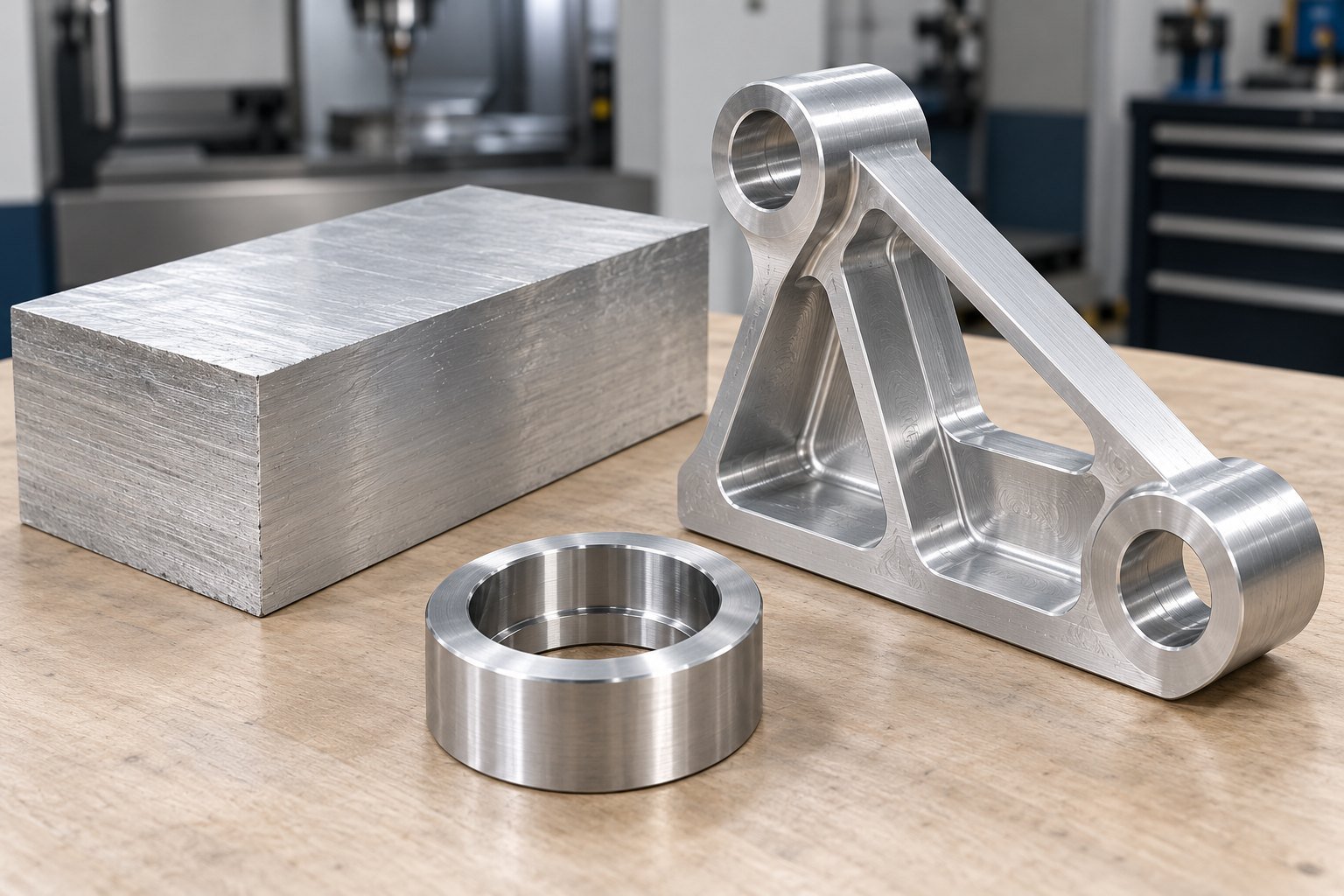
For 7075 aluminum machined parts, start with the property and interface that control your drawing. When comparing a 7075 aluminum parts manufacturer, ask for a clear stock, machining, finish and inspection scope.
For 7075-T6 machined parts, retain the exact stock form and temper through procurement. Discuss the operating environment and approved joining method alongside the strength requirement.
7075-T651 CNC machining needs a suitable stock, material-removal and dimensional-control plan. Keep the callout explicit rather than treating similar typical values as interchangeability approval.
Kaiser identifies improved stress-corrosion resistance for these conditions compared with T6/T651. Review the associated property specification before proposing a temper change.
T6 is solution heat treated and artificially aged. T651 adds stress relief by stretching under the applicable product standard. For 7075 t651 aluminum, confirm the actual product form and specification; the suffix is not an automatic strength upgrade.
For 7075 t73 aluminum, review the overaged condition when stress-corrosion resistance is a design concern. Temper substitution requires your approval.
Precision 7075 aluminum machining starts with your datum scheme, stock condition and finished-part acceptance.
For pocketed brackets and mounting faces, 7075 aluminum precision milling needs accessible internal radii, stable references and a controlled removal sequence.
Explore the process →For collars, sleeves and hubs, relate bore, outside diameter and shoulder requirements to a common inspection scheme.
Explore the process →Review multi-face access and clamping clearance for your geometry. Select the route that preserves critical relationships with suitable setups.
Explore the process →For 7075-T6 CNC machining and 7075-T651 CNC machining, identify the specified material condition before route approval.
For 7075 aluminum thin wall machining, identify webs, pockets and long unsupported features. Review stock allowance and balanced roughing before final dimensions are produced.
Review your drawing →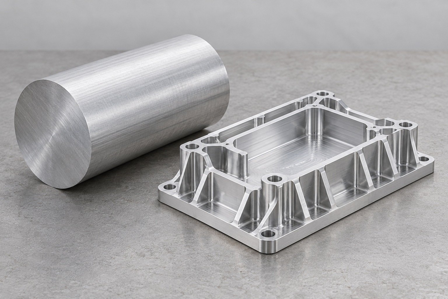
Locate bores, faces and mounting patterns from the approved datum scheme. Specify the unclamped inspection condition where relevant.
Review your drawing →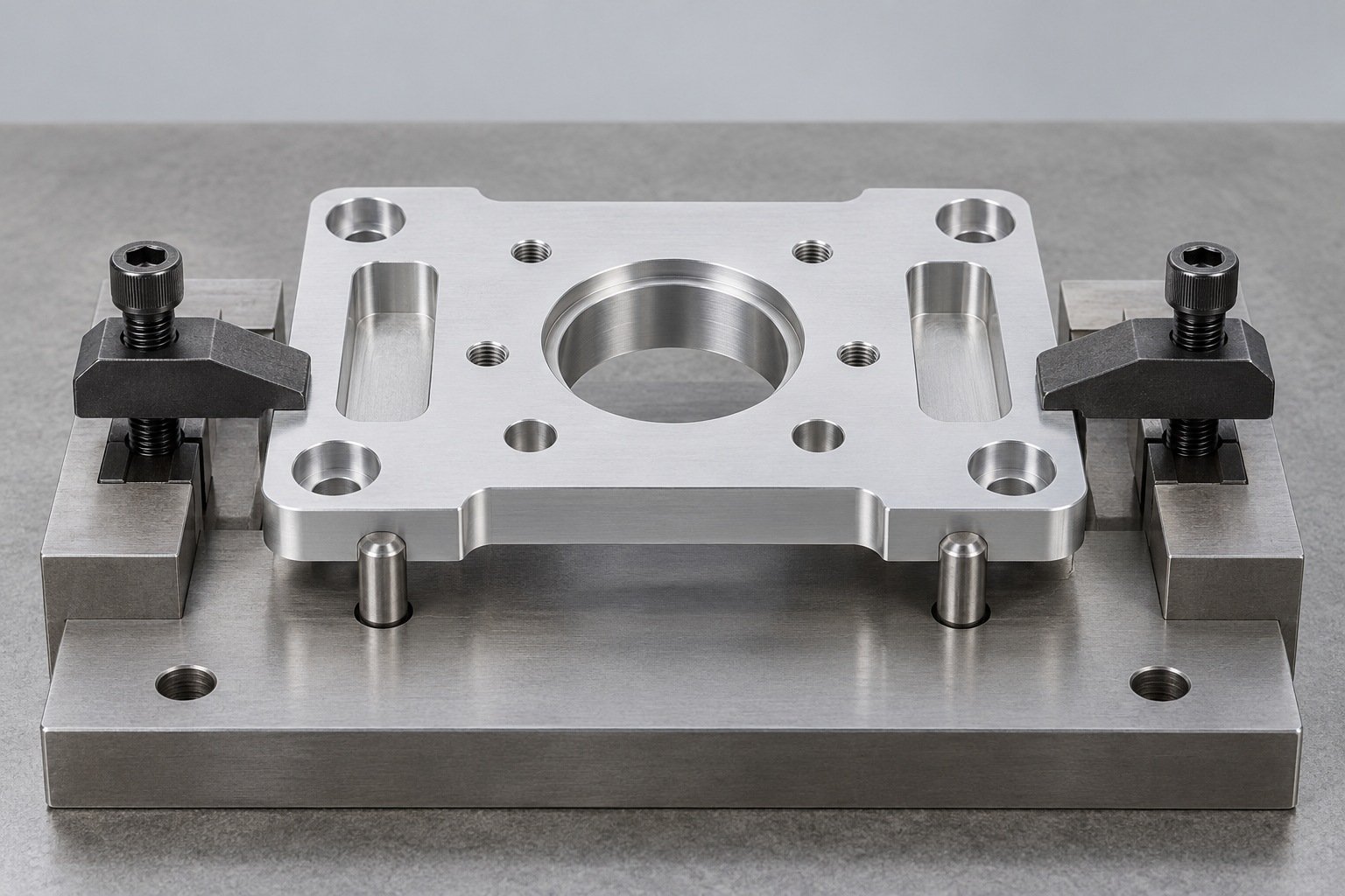
Check pocket radii, reach and obstructions together. A small internal radius can drive tool length, access and inspection decisions.
Review your drawing →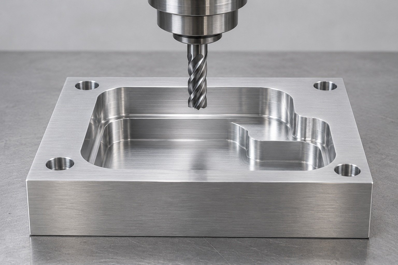
Define fit, surface texture and coating condition for your bore and mating component. Keep masking and post-treatment inspection visible on the drawing.
Review your drawing →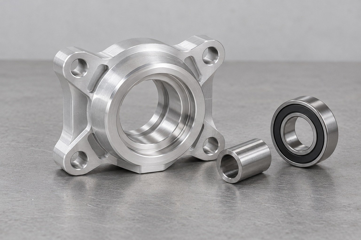
Identify fatigue-sensitive faces and edges. Material typicals alone do not prove service life; agree drawing requirements, finishing and any required qualification evidence.
Review your drawing →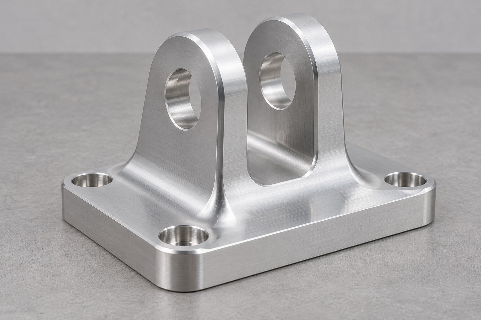
Review exposed and mating surfaces, dissimilar metals and retained moisture. Select the temper and protective system for the actual environment.
Review your drawing →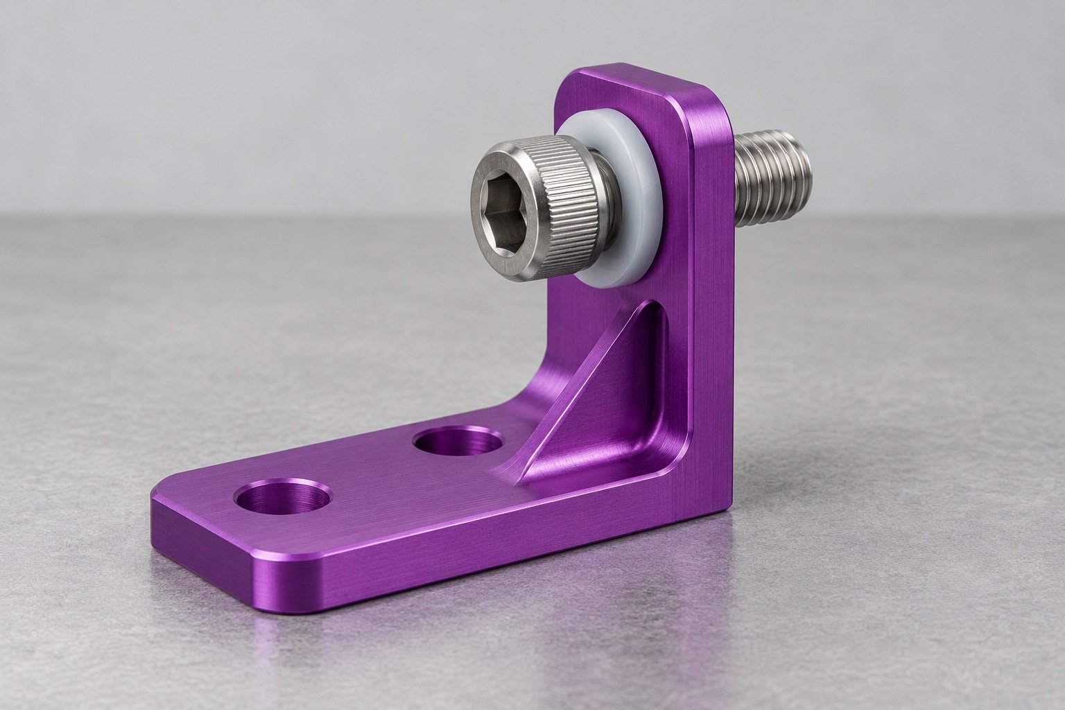
YOUR MATERIAL REFERENCE
Switch between strength, physical properties and chemical limits. Keep the stated product form, temper and test conditions with the numbers.
TYPICAL DATA, WITH CONDITIONS
Compare strength and elongation in the same product context before selecting your material condition.
| Typical property | O | T6 / T651 | T73 / T7351 |
|---|---|---|---|
| Tensile strength | 228 MPa / 33 ksi | 572 MPa / 83 ksi | 503 MPa / 73 ksi |
| Yield strength | 103 MPa / 15 ksi | 503 MPa / 73 ksi | 434 MPa / 63 ksi |
| Elongation / 4D | 17% | 11% | 13% |
| Brinell hardness | 60 HB | 150 HB | Not listed |
| Ultimate shear strength | 152 MPa | 331 MPa | 303 MPa |
| Elastic modulus | 71.0 GPa | 71.0 GPa | 71.0 GPa |
Typical rod/bar values, not design allowables or purchase minima. Tensile specimen: 0.500-inch diameter; hardness test: 500 kg, 10 mm ball. Direction, section and applicable specification matter. Missing hardness is not a zero.
Kaiser source and test conditions →| Physical property | Typical value / condition |
|---|---|
| Density | 2.80 g/cm³ at 20°C |
| Melting range | 532–635°C |
| Linear thermal expansion | 23.4 µm/m·K, 20–100°C |
| Thermal conductivity | 130 W/m·K T6/T651; 155 W/m·K T73/T7351, at 20°C |
| Electrical conductivity | 33% / 40% IACS respectively, equal volume at 20°C |
T651 stress relief does not make every machined shape distortion-free. The higher typical elongation of T73/T7351 accompanies a lower typical strength in this reference.
Thermal expansion matters for bearing fits and mixed-material assemblies. Check service temperature and the drawing’s inspection condition together.
Typical rod/bar physical values. Conditions and temper are shown beside each value.
Kaiser source and test conditions →YOUR MATERIAL IDENTITY
Use these chemical limits to review the material record for your specified stock. Chemistry identifies the alloy; it does not establish temper, mechanical acceptance or a finished part’s load rating.
| Element | Weight % |
|---|---|
| Zinc (Zn) | 5.10–6.10 |
| Magnesium (Mg) | 2.10–2.90 |
| Copper (Cu) | 1.20–2.00 |
| Chromium (Cr) | 0.18–0.28 |
| Silicon (Si) | ≤0.40 |
| Iron (Fe) | ≤0.50 |
| Manganese (Mn) | ≤0.30 |
| Titanium (Ti) | ≤0.20 |
| Other elements | ≤0.05 each; ≤0.15 total |
| Aluminum (Al) | Remainder |
Composition limits: Kaiser 7075 Rod & Bar technical data, p.2. Aluminum remainder is the balance after the listed elements. Your purchase specification controls acceptance.
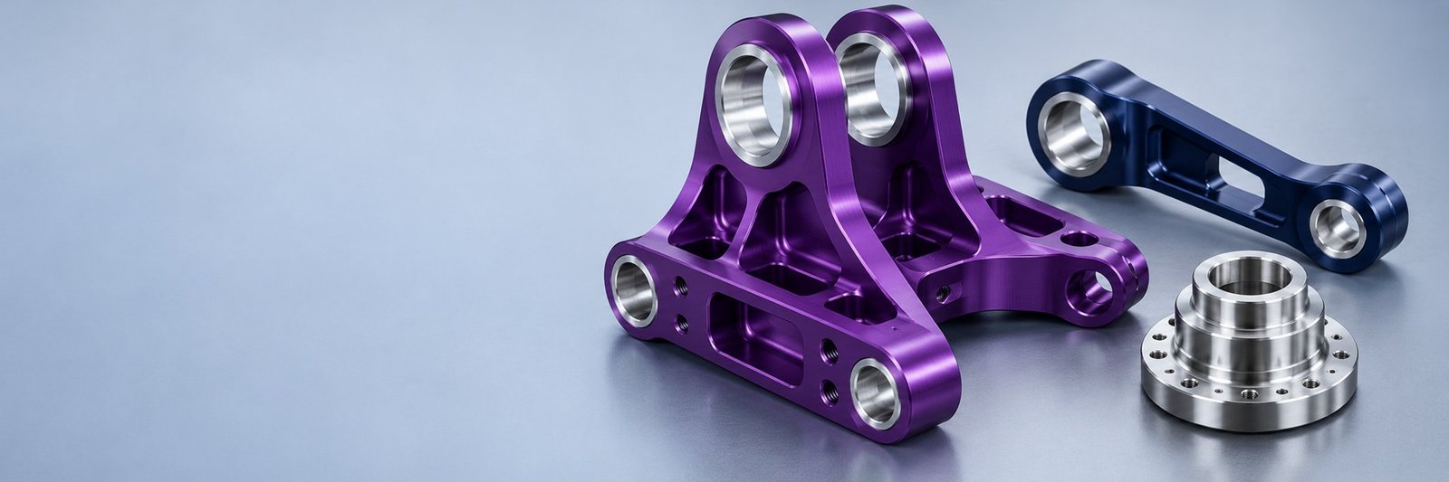
Read the manufacturer data →Linkages, clamping components, pivot fittings and precision mounts show how geometry and interfaces drive a review. The illustrations do not establish a qualified aerospace part or verified load rating. Keep design authority, qualification and production scope separate.
Concept geometry and color illustrate the topic; no customer case or tested performance is implied.
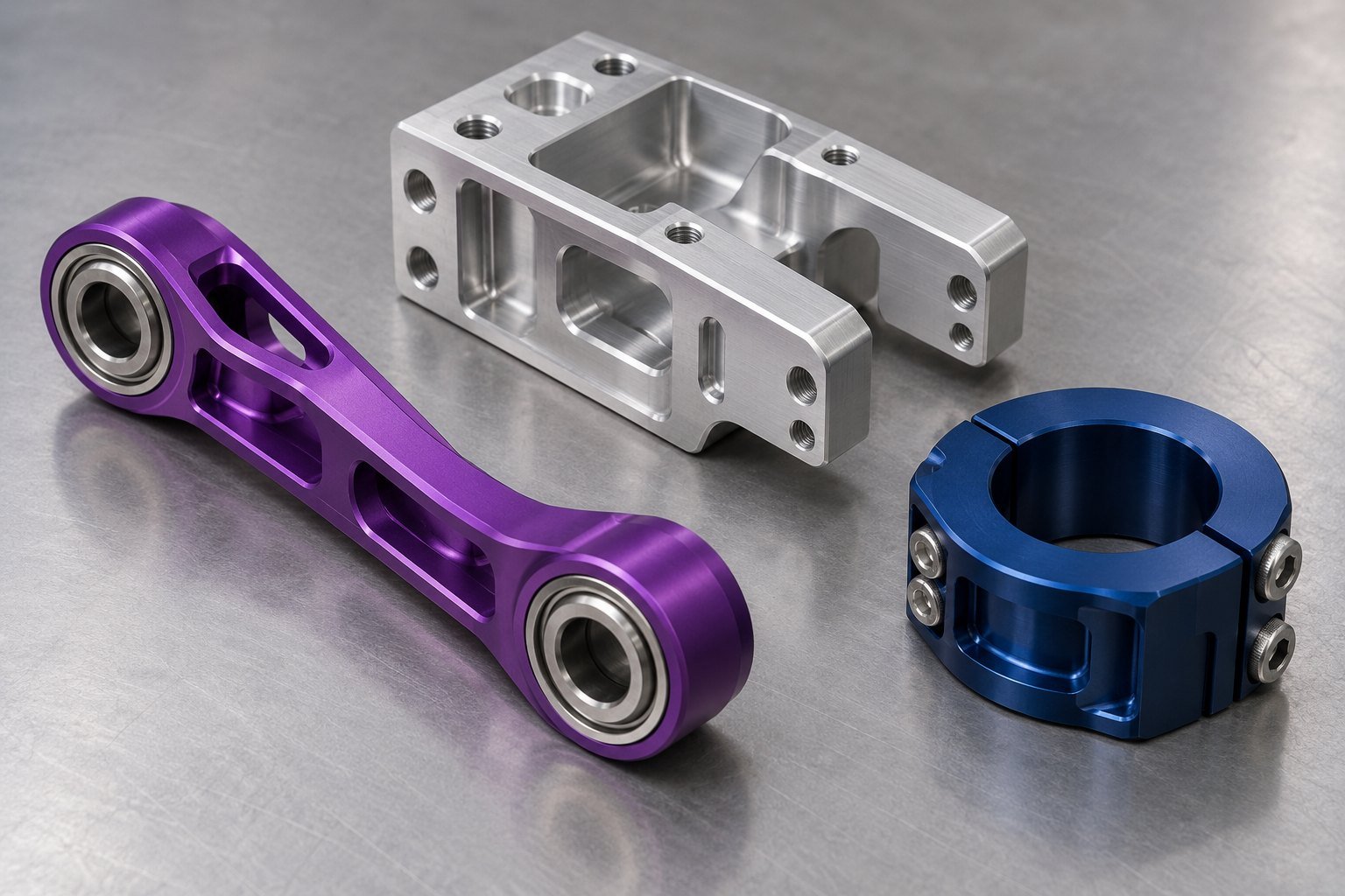
Define load direction, mounting faces and the approved design revision.
Review moving mass, bearing alignment, repeated loads and assembly interfaces.
Use your geometry and service environment to decide whether the higher-strength condition adds useful value.
Discuss the exact anodizing or coating system for your service environment. Do not assume that a purple or black concept finish proves corrosion performance. Identify the bearing seats, threads, electrical contacts and cosmetic faces that require masking or specific treatment.
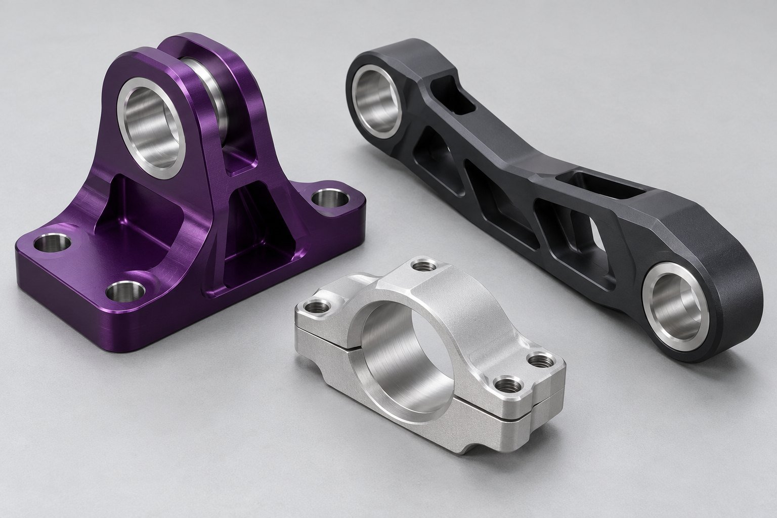
Approve an appearance sample and specified protective system. Keep color, sealing and masked features explicit.
Discuss wear surfaces, coating thickness, fit allowances and fatigue-sensitive features before treatment.
Define marking location, legibility and packaging so exposed faces are protected during the agreed handling route.
| Your comparison | What to review |
|---|---|
| 7075 vs 6061 | Compare the required strength condition with corrosion, joining, geometry and cost. A stronger nominal alloy is not automatically a better complete design. |
| T6/T651 vs T73/T7351 | Compare the actual property and stress-corrosion requirements for the environment, not just one tensile value. |
| Machined part vs assembly | Review whether a bolted component, bushing or mating part better addresses the interface. Do not assume 7075 can follow a conventional 6061 welding route. |
Explore Aluminum Alloy Alternatives →
Compare required strength with joining, corrosion, available stock and the full finished-part cost. Where a welded fabrication or general-purpose component meets your requirement, review 6061 as an alternative before committing to 7075.
Compare 6061 Aluminum →Product form, size, certification and approved substitutions.
Deep pockets, thin webs, setup access and finished envelope.
For small batch 7075 CNC machined parts, distinguish trial quantity from recurring demand.
Coating, masking, visible faces and protection during handling.
Inspection scope, traceability, first-article records and packaging requirements.
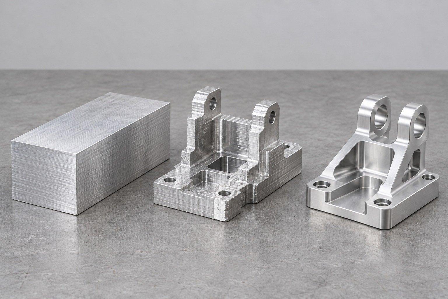
For 7075 aluminum prototype machining, define what your sample must demonstrate and which production conditions it represents.
Review cost drivers →Link the alloy, temper, product form and approved drawing to the supplied material record.
Identify the bores, datums, bearing seats and alignment features that need agreed inspection evidence.
Define the protective system, masked areas and any application-specific verification or acceptance criteria.
State any required sector, fatigue, load or special-process approval explicitly. General manufacturing information is not proof of a qualification.
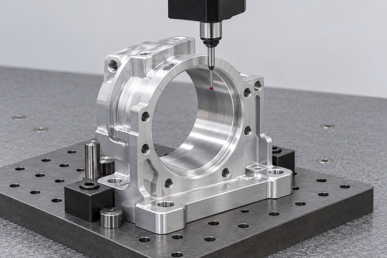
01 CAD and approved design revision
02 7075 stock form, temper and specification
03 Critical load-path and mating features
04 Approved joining and finishing requirements
05 Quantities and requested delivery
06 Inspection, traceability and qualification scope
Identify any open requirements, proposed substitutions or reference-only data. Your team can then compare the material, process and inspection scope on the same basis.
For your 7075 aluminum CNC machining quote, separate mandatory requirements from preferences so your team can compare equivalent finished-part scopes.
No. The material change requires design and procurement approval. Review properties, stock form, temper, corrosion, joining, finish and any qualification requirements.
Do not assume a conventional fusion-welding route is suitable. Review an approved joining method and qualified procedure for the actual application. Bolted joints and other design approaches may need consideration.
Identify the bearing interface, datum scheme, tolerance, surface condition and any post-finish requirement. Agree how and when the critical dimensions will be inspected.
It can suit a high-strength machined design when stock condition, corrosion protection, joining and inspection are addressed together. Material selection follows your complete requirements.
Yes, protective and hard anodizing are options to review. Agree the specified system, appearance, masking, thickness and final dimensions. A colored concept does not prove coating performance.
Review stress-relieved stock where approved, roughing and finishing sequence, support and unclamped checks. No temper or single machining method guarantees zero movement for every geometry.
Send CAD and a controlled drawing, alloy/temper and product specification, quantities, critical interfaces, finish, inspection and records. Identify open requirements separately.
Feasibility depends on geometry, stock, feature relationships, coating and inspection method. Mark critical tolerances on your drawing for project review; a blanket number is not a finished-part commitment.
State the program, certificates, special processes and approval requirements for review. An alloy’s use in aerospace does not establish LK MFG’s approval for a specific program or critical component.
Provide the design authority’s material, load, fatigue, finish and documentation requirements. Any supply qualification must be confirmed for your project before acceptance.





