

Injection Molding
Tooling and molding for your repeat plastic parts.
From prototype to production, coordinated manufacturing solutions for your custom parts.
View All Services →
Precision parts for your tight tolerances and complex geometry.
Tooling and molding for your repeat plastic parts.

Metal casting options for your part and production volume.

Cutting, forming and welding for your fabricated parts.

Custom profiles for your section, length and finish requirements.

Finishes for your appearance, corrosion and wear requirements.

Sub-assemblies and final builds for your production program.

Production tooling built around your process and volume.

Prototype parts to check fit, function and design.
DFM, process planning and production support for your project.
Inspection, documentation, inventory and delivery planning for your program.
Choose air- or liquid-cooling components around your thermal and mechanical requirements.

Manufacturing support for your cold plates, manifolds and cooling assemblies.

Find components for your power electronics, energy, laser and telecom application.

Components for your electronic systems.
Start with your functional and quality requirements.
Build around your operating environment.
From prototype to production, review material performance, manufacturability and cost for your part.
Review grade, temper and finish for your metal parts.
 AluminumStrength, weight and machining›
 Stainless SteelCorrosion and finish requirements›
 Carbon & Alloy SteelDiscuss grade and heat treatment›
 Tool SteelDiscuss tooling and wear needs›
 TitaniumReview grade and part geometry›
 Copper & BrassDiscuss conductivity and machining›
Match your polymer to function, process and environment.
 ABSReview enclosure and molding needs›
 Polycarbonate (PC)Discuss clarity and impact needs›
 Nylon (PA)Review moisture and wear conditions›
 POM / AcetalReview fit and sliding features›
 PEEKDiscuss operating conditions›
 PTFEReview friction and chemical exposure›
 ULTEM / PEIDiscuss thermal and electrical needs›
Confirm grade availability and application requirements.
 Silicone / LSRDiscuss flexible component needs›
 TPU / TPEReview flexibility and processing›
 EPDMReview weathering and chemical exposure.›
 NBRReview oil and fuel exposure.›
 FKMReview temperature and chemical exposure.›
 G10 / FR4Review insulation and laminate needs›
 CompositesReview stiffness, weight and laminate.›Customer-Specified MaterialsConfirm your grade and requirements.›Other Specialty MaterialsDiscuss your application and grade.›
Practical guidance for your part geometry and material decisions.
Prepare your process, budget and sourcing questions.
Build your knowledge before production.
Learn who we are and how we operate.
Find our U.S. support team or start a conversation.
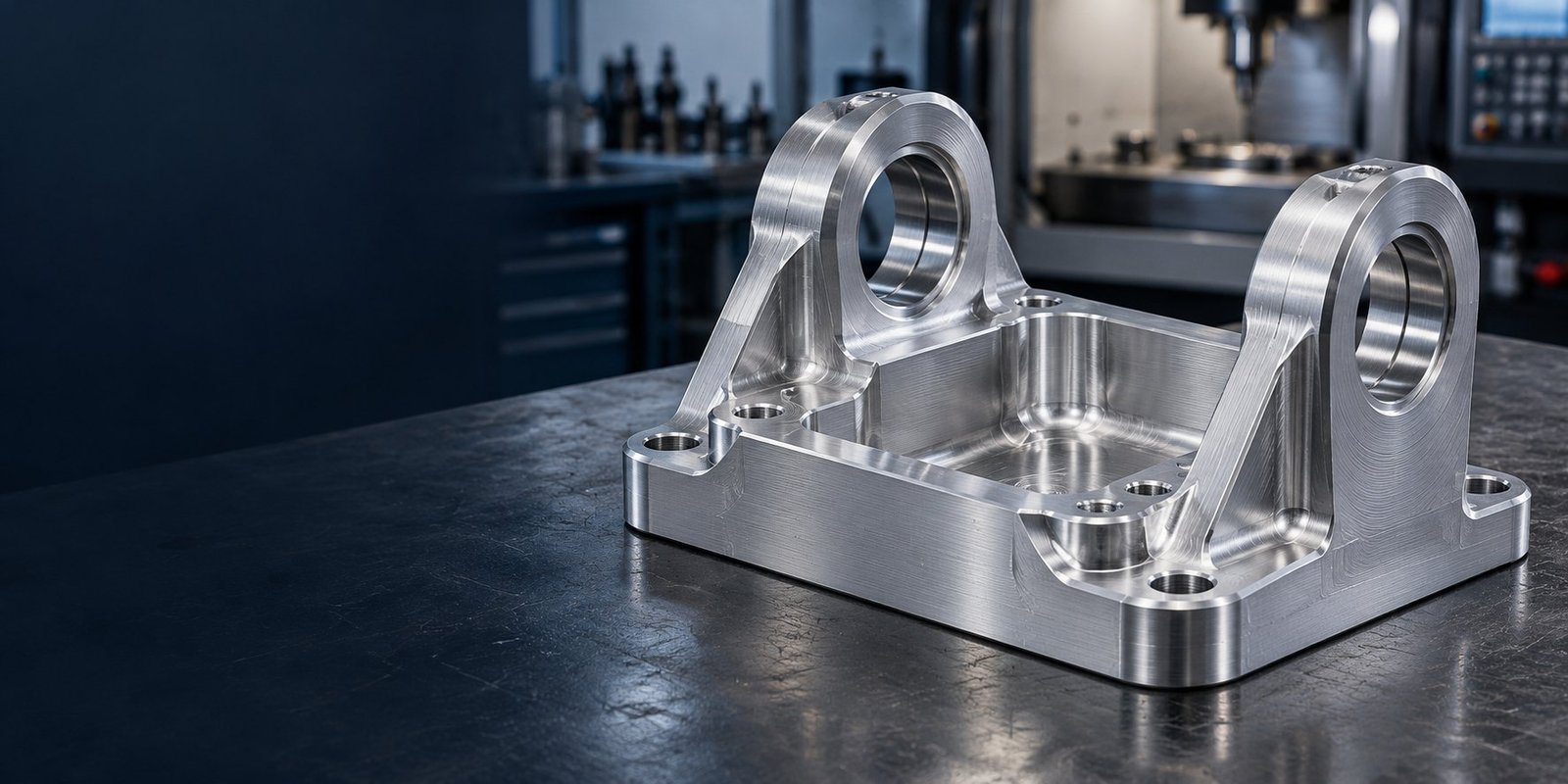
For your 6061 aluminum CNC machining project, agree the temper, critical features and finish before ordering. Review your prototype and repeat parts on one controlled drawing.
For custom 6061 aluminum parts, compare the required strength, geometry, corrosion exposure and finish with the exact stock form and temper. Welding or brazing can make 6061 worth reviewing; forming can lead you toward O or T4 rather than a T6 starting condition.
6061 aluminum machinability still needs suitable tool access and a clamping plan. The right alloy is the one that meets your finished-part requirement.
Review pockets, bores and mating datums.
CNC Machining →Define what your first parts need to prove.
Prototype Support →Agree appearance and final dimensions.
Anodizing →| Property | Typical value | Unit |
|---|---|---|
| Density (20 °C) | 2.70 | g/cm³ |
| Ultimate tensile strength (T6/T651) | 310 | MPa |
| Yield strength (T6/T651) | 276 | MPa |
| Elongation / 4D (T6/T651) | 17 | % |
| Brinell hardness (T6/T651) | 95 | HB |
| Thermal conductivity (20 °C, T6/T651) | 167 | W/(m·K) |
Typical reference values, not purchase minima. Mechanical values use the source’s 0.500-inch tensile specimen; stock form, specification and actual material records govern acceptance.
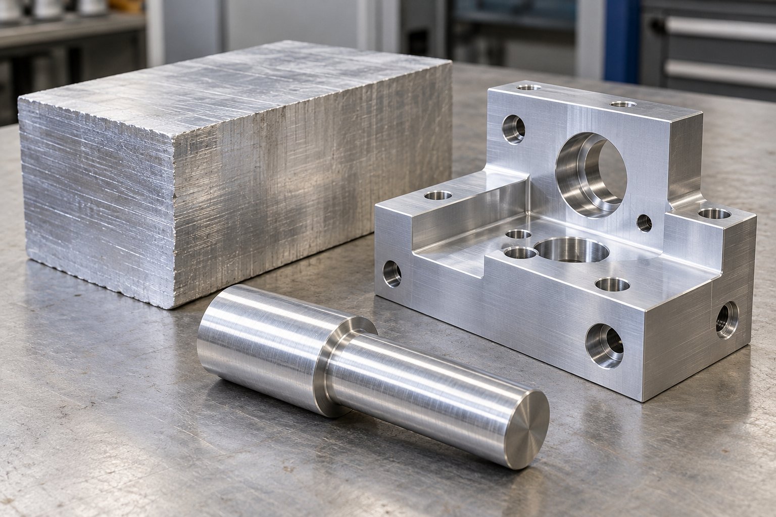
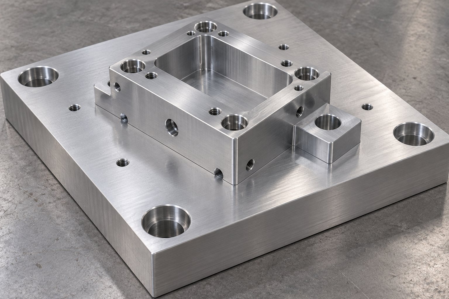
For 6061-T651 CNC machining, agree the exact condition and applicable product standard. T651 does not guarantee zero distortion.
| Temper | UTS ksi / MPa | Yield ksi / MPa | Elongation / 4D | HB | Shear ksi / MPa | Fatigue ksi / MPa | Modulus 10³ ksi / GPa |
|---|---|---|---|---|---|---|---|
| T451 | 35 / 241 | 21 / 145 | 25% | 65 | 24 / 165 | 14 / 97 | 10.0 / 68.3 |
| T6, T651 | 45 / 310 | 40 / 276 | 17% | 95 | 30 / 207 | 14 / 97 | 10.0 / 68.3 |
Tensile values: 0.500-inch-diameter specimen; elongation measured over 4D. Brinell test: 500 kg load, 10 mm ball. Fatigue values refer to 5 × 10⁸ reversed-stress cycles, R.R. Moore type; they are not a guaranteed service fatigue limit.
| Weight % | Si | Fe | Cu | Mn | Mg | Cr | Zn | Ti | Other: each | Other: total |
|---|---|---|---|---|---|---|---|---|---|---|
| Minimum | 0.40 | — | 0.15 | — | 0.8 | 0.04 | — | — | — | — |
| Maximum | 0.8 | 0.7 | 0.40 | 0.15 | 1.2 | 0.35 | 0.25 | 0.15 | 0.05 | 0.15 |
Dashes mean no minimum is listed in this source, not a zero-content claim. Compare the applicable material specification and lot certificate; a photograph cannot establish alloy identity.
| Characteristic / condition | English | Metric |
|---|---|---|
| Nominal density, 68 °F / 20 °C | 0.098 lb/in³ | 2.70 Mg/m³ |
| Melting range | 1080–1206 °F | 582–652 °C |
| Specific heat, 212 °F / 100 °C | 0.214 BTU/(lb·°F) | 896 J/(kg·K) |
| Linear thermal expansion, 68–212 °F / 20–100 °C | 13.1 µin/(in·°F) | 23.6 µm/(m·K) |
| Volumetric thermal expansion, 68 °F / 20 °C | 3.93 × 10⁻⁵ in³/(in³·°F) | 71 × 10⁻⁶ m³/(m³·K) |
| Thermal conductivity at 68 °F / 20 °C — O | 104 BTU/(ft·h·°F) | 180 W/(m·K) |
| Thermal conductivity at 68 °F / 20 °C — T451 | 89 BTU/(ft·h·°F) | 154 W/(m·K) |
| Thermal conductivity at 68 °F / 20 °C — T6/T651 | 97 BTU/(ft·h·°F) | 167 W/(m·K) |
| Electrical conductivity, equal volume — O | 47% IACS | 47% IACS |
| Electrical conductivity, equal volume — T451 | 40% IACS | 40% IACS |
| Electrical conductivity, equal volume — T6/T651 | 43% IACS | 43% IACS |
| Electrical conductivity, equal weight — O | 155% IACS | 155% IACS |
| Electrical conductivity, equal weight — T451 | 132% IACS | 132% IACS |
| Electrical conductivity, equal weight — T6/T651 | 142% IACS | 142% IACS |
Temperature and temper matter to thermal design. Equal-weight electrical figures are a mass-normalized comparison; they do not mean higher equal-volume conductivity than copper. Confirm the values required for your design.
| Temper | General corrosion | Stress corrosion | Cold workability | Machinability | Anodize response | Brazeability | Gas weld | Arc weld | Spot weld |
|---|---|---|---|---|---|---|---|---|---|
| O | B | A | A | D | A | A | A | A | B |
| T451 | B | B | B | C | A | A | A | A | A |
| T6, T651 | B | A | C | C | A | A | A | A | A |
Letters are comparative ratings within the source, not certification or a promise of suitability. Corrosion/machinability use A–E, cold workability A–D and anodize response A–C in decreasing merit. Joining ratings A–D run from generally weldable to no commonly used method. Stress-corrosion ratings reflect source test/service conditions, including 3.5% sodium chloride alternate immersion; assess your actual load and environment.
Source: Kaiser Aluminum, Alloy 6061 Sheet, Coil & Plate technical data, Rev. 05/06; user-supplied data sheets. Read the source data →
Choose the route around your geometry, functional features and inspection plan. For precision 6061 aluminum machining, define the dimensions that matter to your assembly.
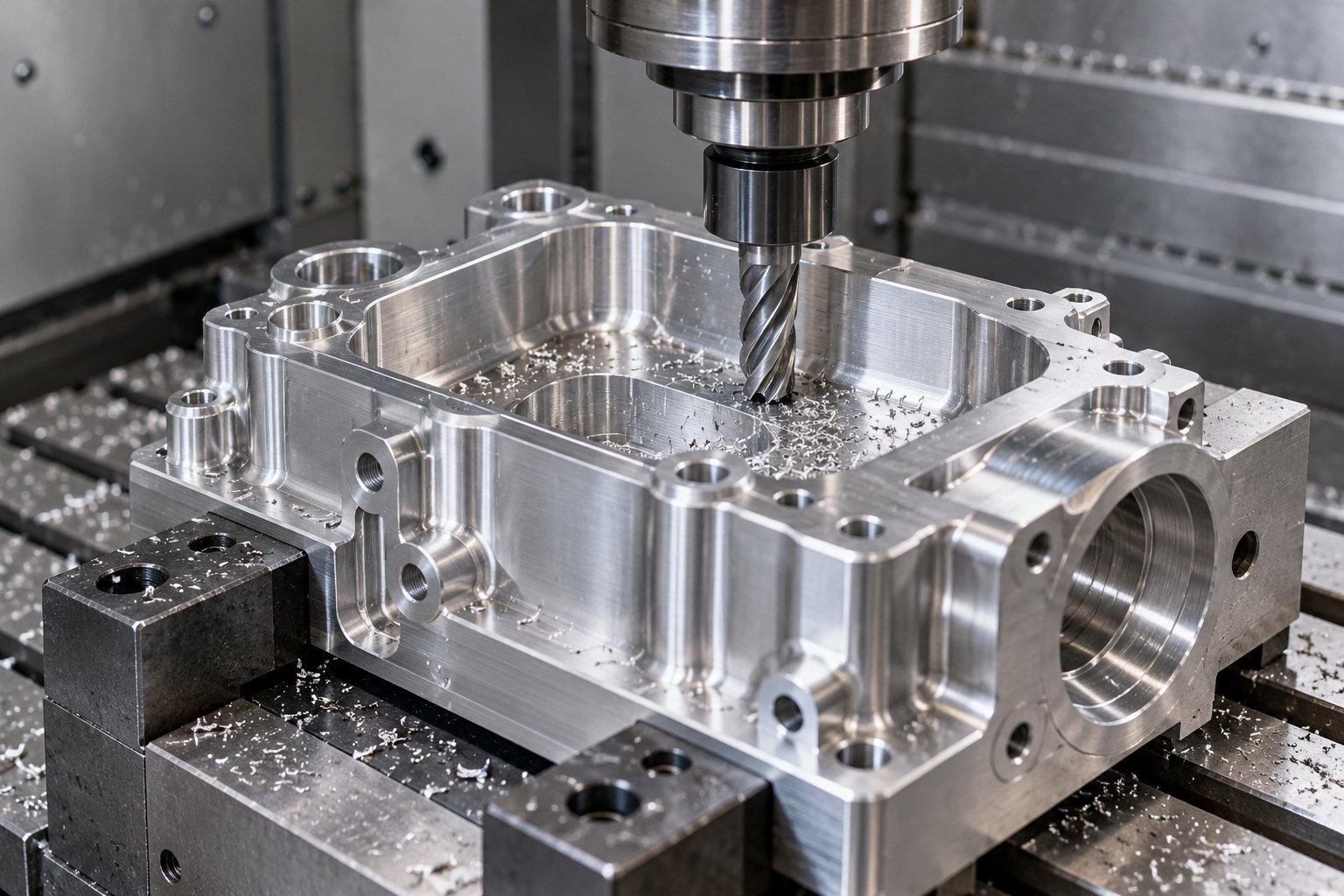
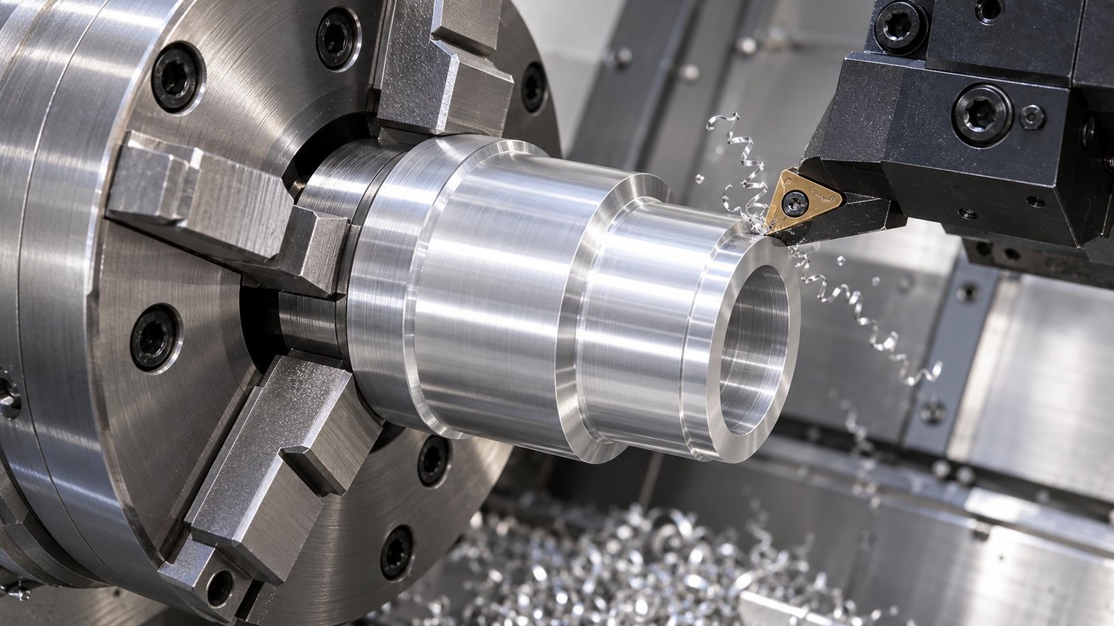
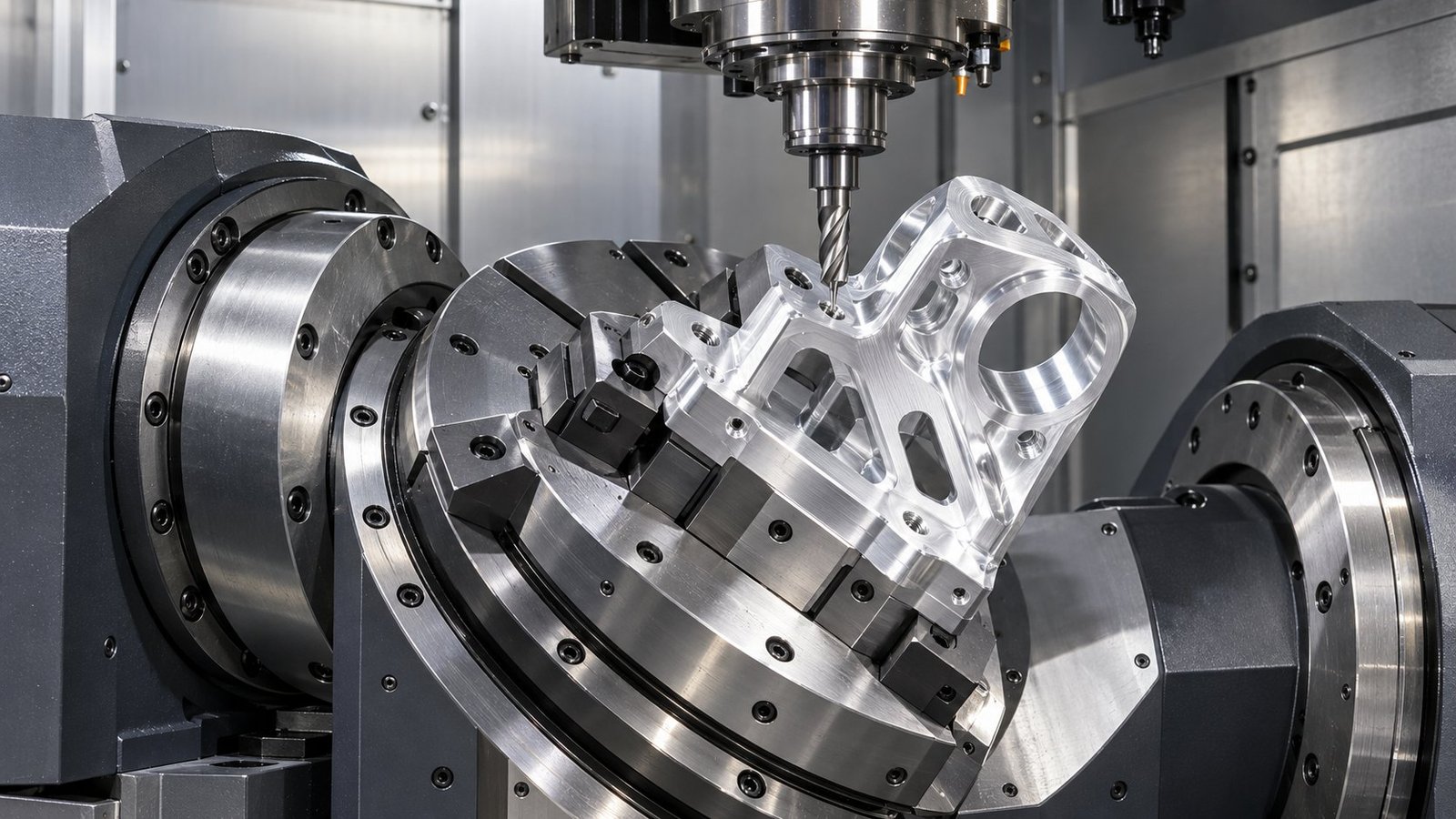
Illustrative machining concepts, not documentary machine photographs or a universal tolerance promise. Review the actual drawing for feasibility.
For anodized 6061 aluminum parts or another specified finish, agree appearance and final dimensions together. Specify the finish rather than choosing it from a photograph.
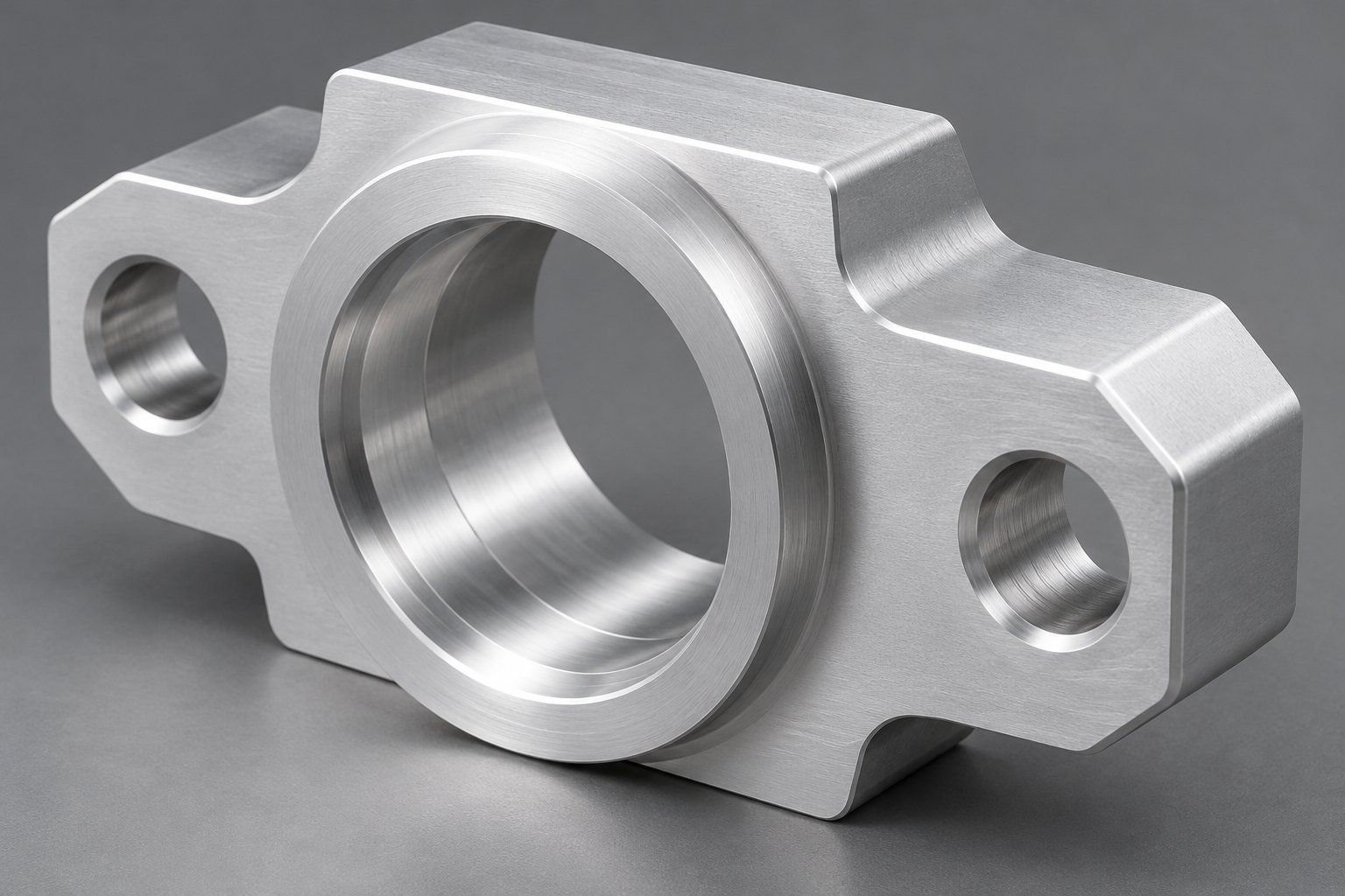
Surface preparation, thickness, racking and final fits.
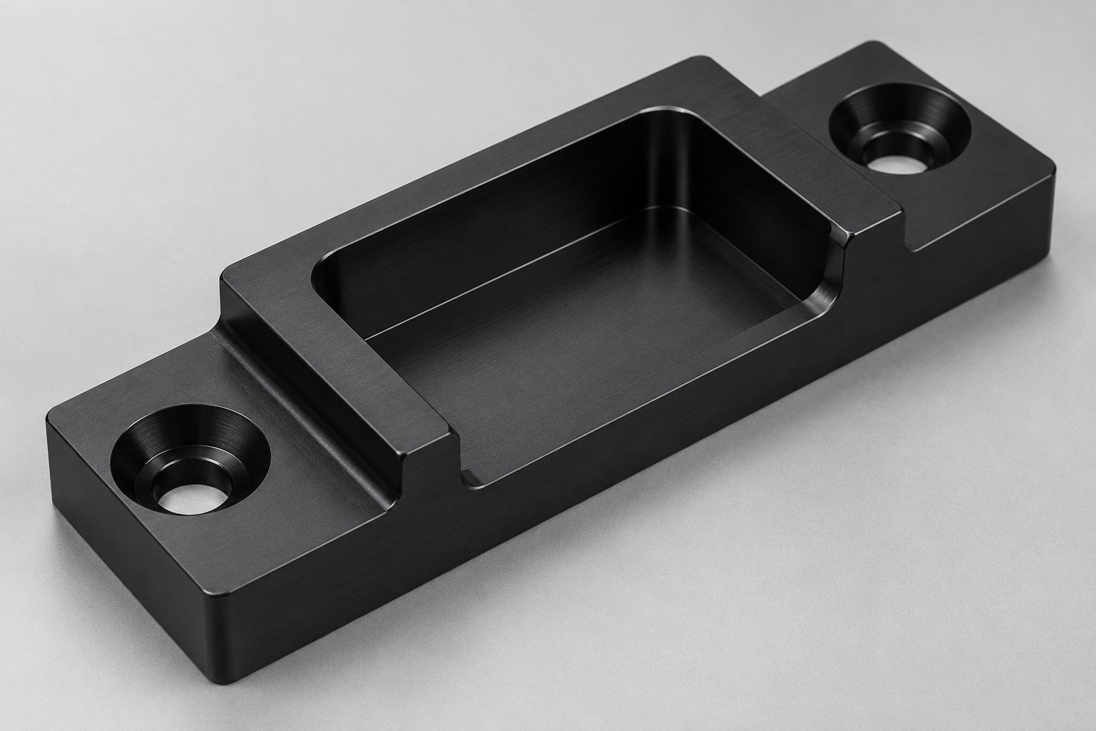
Color reference, visible faces and allowed variation.
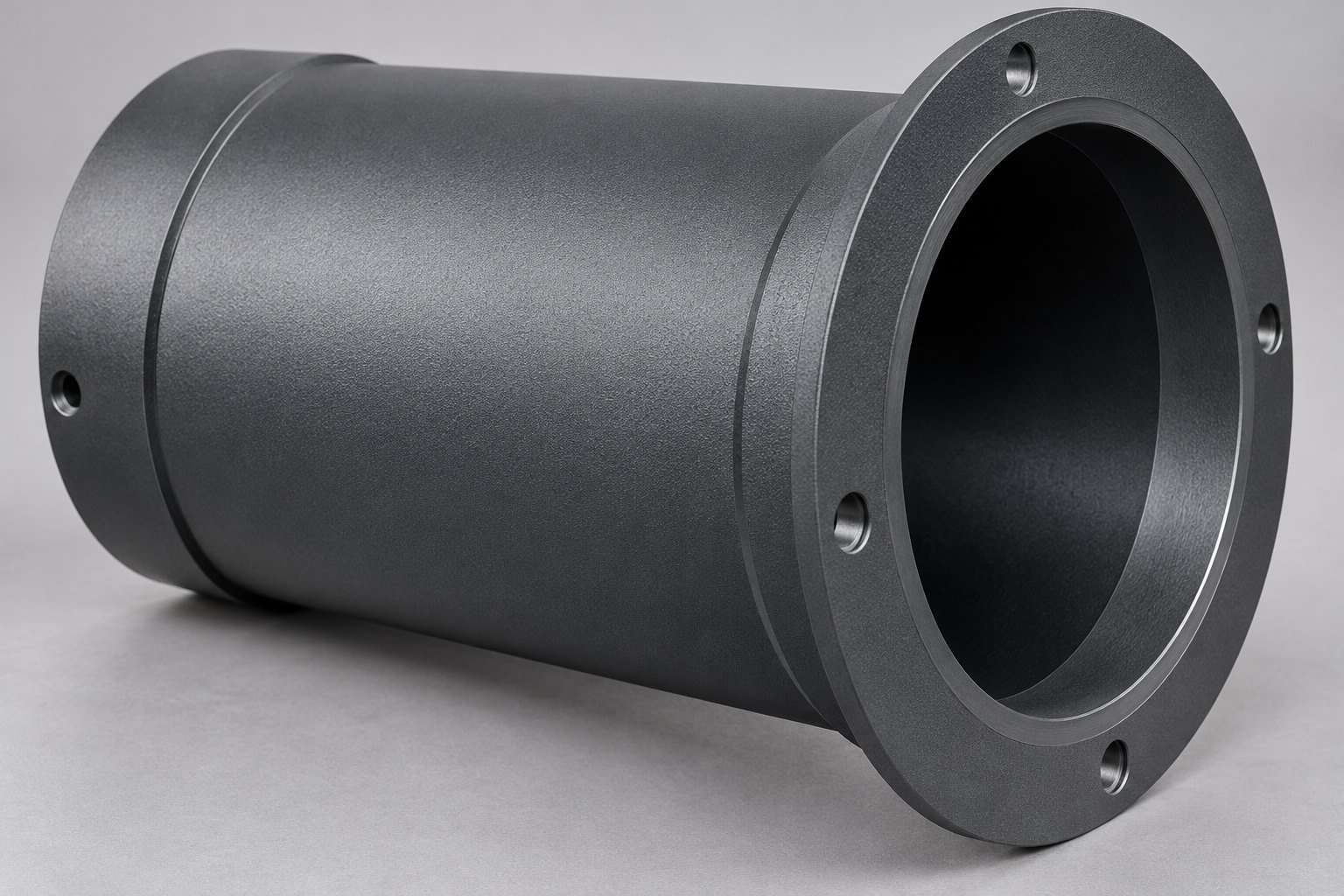
Gloss, texture, masking and final assembly clearance.
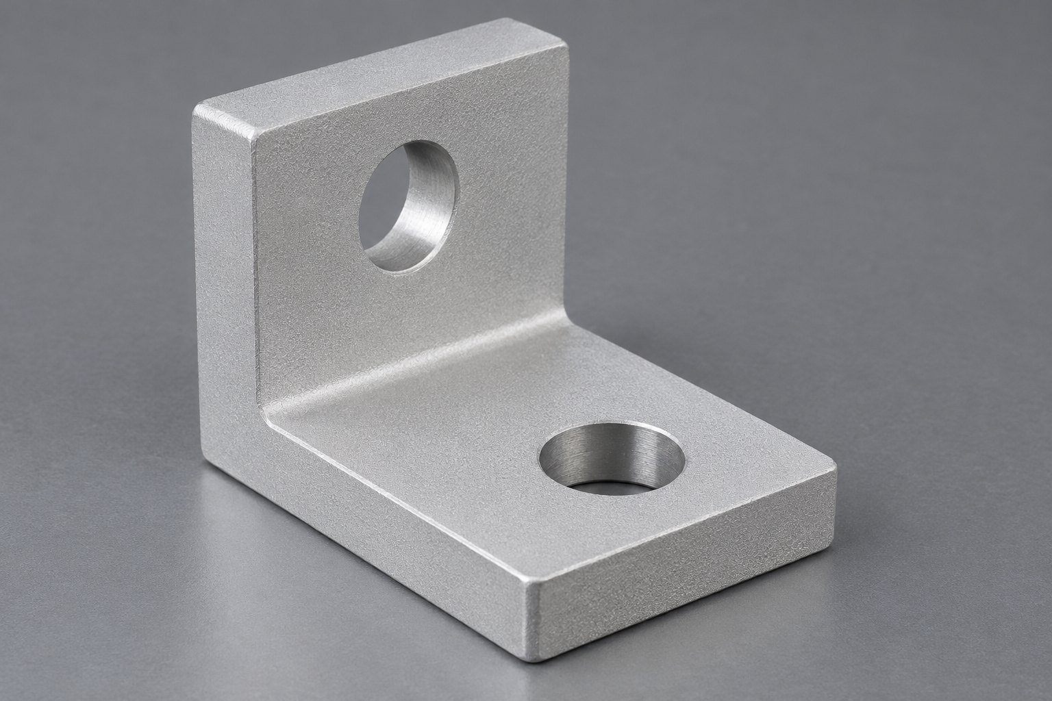
Texture, masked features and subsequent protection.
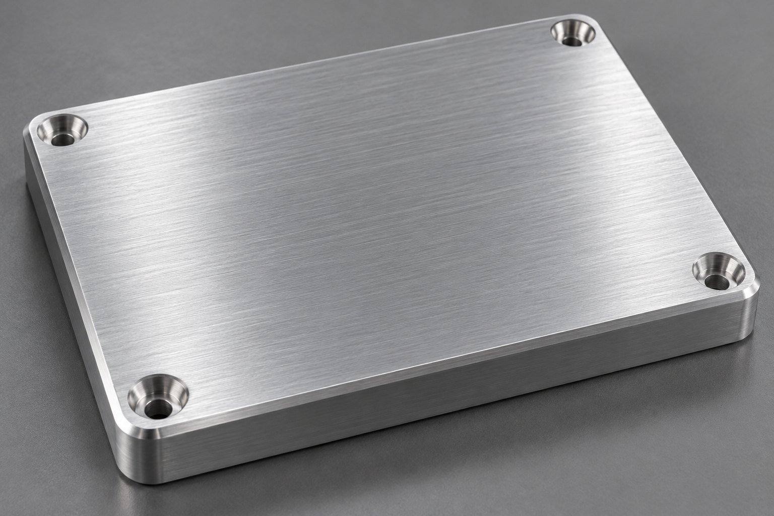
Grain direction, appearance faces and edge condition.
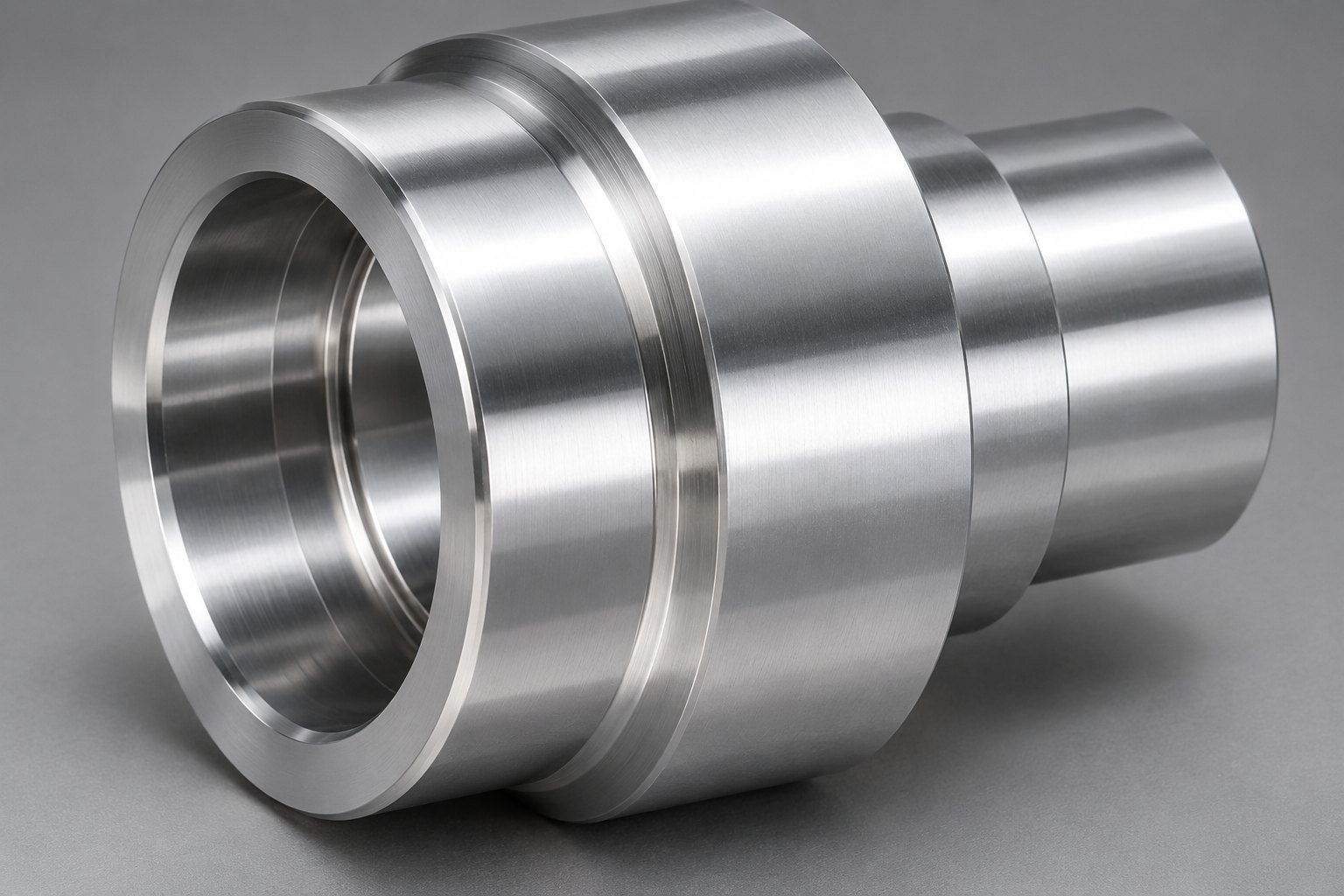
Appearance target, edge retention and protection.
For black anodized 6061 aluminum parts, agree the sample and masking requirements. Brushing and polishing are appearance operations, not a substitute for a specified protective coating. Availability is confirmed with your order.
These example geometries help frame the review for your 6061 aluminum machined parts. Your design, material specification and application requirements determine suitability.
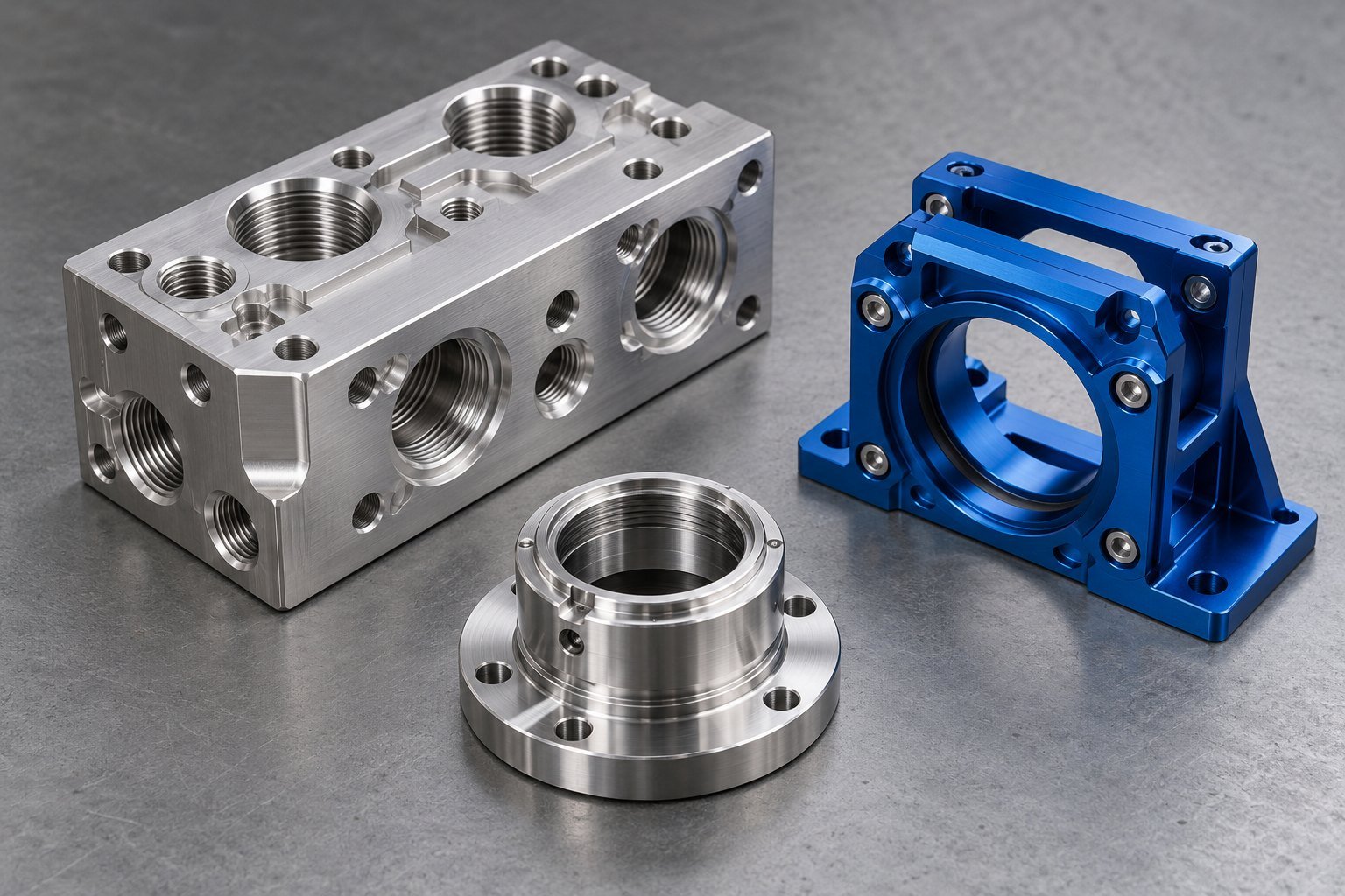
Mating datums, bores and service access.
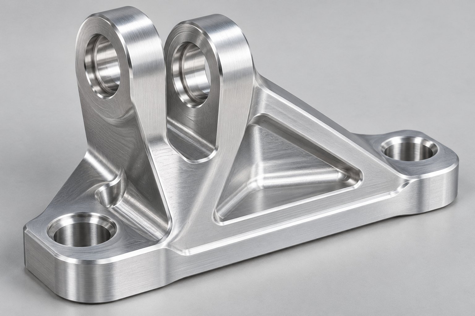
Mounting interfaces, load and environment.
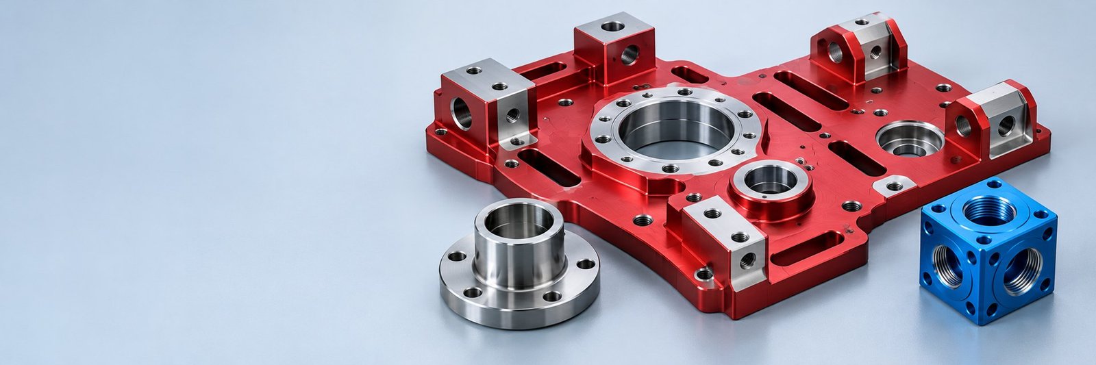
Alignment faces and fastener locations.
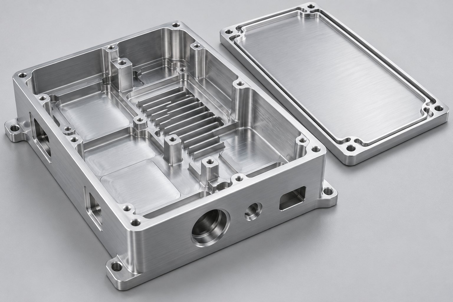
Connector openings, covers and finish.
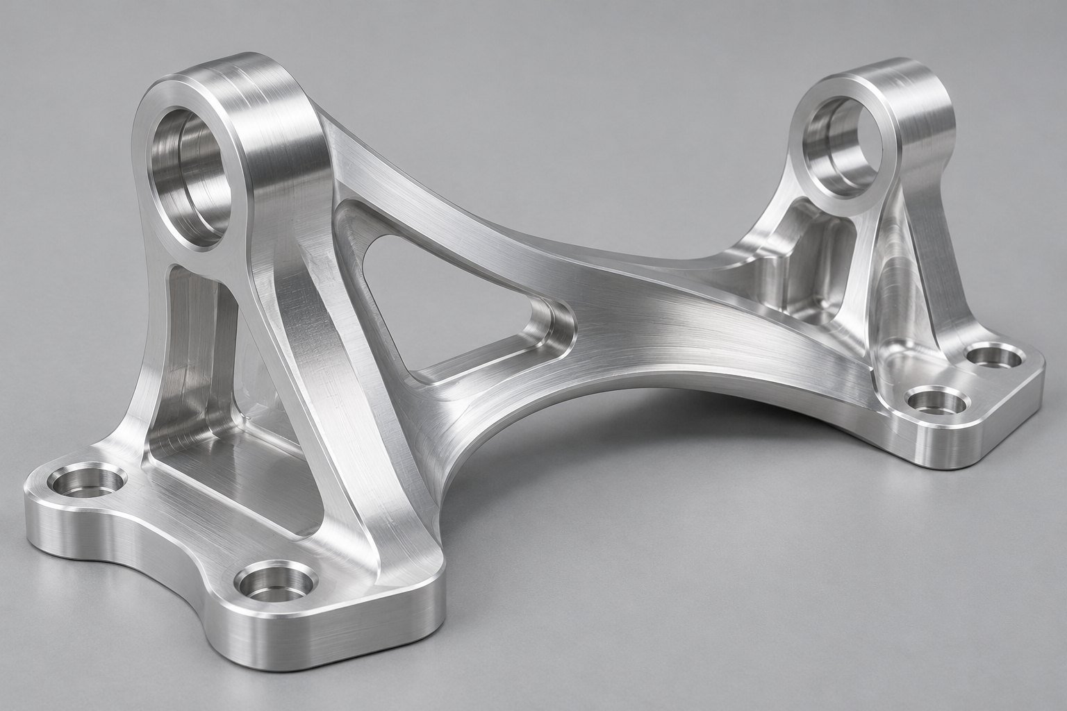
Drawing scope and qualification requirements.
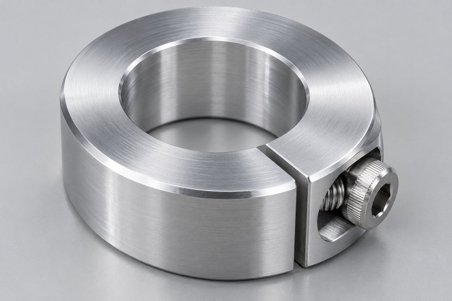
Fits, appearance and repeat acceptance.
Illustrative part concepts; no customer program, certified aerospace use or tested component performance is implied.
Review 6061 for the combined machining, joining, corrosion and finish requirement. Compare 7075 when your specified strength condition controls the design.
Compare Aluminum Alloys →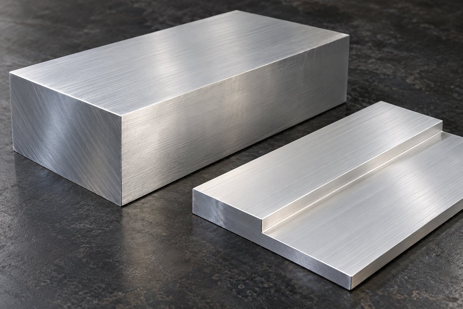
6061 vs 6063: compare a machined part with an extrusion-led design.
6061 vs 5052: compare your machined or welded component with a formed sheet part.
01 CAD plus controlled drawing revision
02 6061 designation, temper and stock form
03 Trial quantity and repeat demand
04 Critical fits, threads and sealing features
05 Finish, color and masked areas
06 Required inspection and material records
Identify any open requirements, proposed substitutions or reference-only data. Your team can then compare the material, process and inspection scope on the same basis.
6061 aluminum machinability, corrosion exposure, joining and finish are useful starting points. Your required load, geometry, product form and exact temper decide whether the material fits the application.
There is no universal best condition. T651 includes stress relief by stretching, but thin walls, removal balance and fixturing can still affect dimensional stability. Review your stock form, specification and required final condition.
Send the controlled drawing and identify critical features. Size, geometry, temper, setups, finish and measurement method determine feasibility. Agree the tolerances and inspection condition for your part instead of applying one blanket value.
The quote depends on stock size and condition, removed material, machining access, setups, quantity, finish and required inspection. A CAD model plus a controlled drawing lets those costs be reviewed on the same finished-part scope.
Hard anodizing may be considered when the specified process and part requirements are suitable. Confirm coating type, thickness, masked fits, appearance and acceptance criteria in your quote. The material designation alone does not guarantee the finished coating performance.
Send the 3D CAD, controlled 2D drawing and revision, material/temper callout, quantities, critical features, finish and documentation requirements. Flag open decisions so they can be resolved before order release.
6061 can be considered for suitable welding procedures, but welding changes the local material condition. Review joint design, final strength, distortion and subsequent treatment against your application.
Ask how the proposed temper and stock will be verified, which revision controls the work, how critical dimensions will be inspected and what finish and lot records are included. Confirm any proposed substitutions before manufacture.
Specify a physical or agreed color reference, gloss/texture, visible faces and allowed variation. Approve the sample and masking requirements for your order; on-screen colors are illustrative.
State the material document, dimensional report, traceability and any special certification needs in the RFQ. Availability and scope must be confirmed for your proposed material and order.
T6, T651 or another controlled condition.
Datum faces, pockets and tool access.
Critical dimensions before or after finish.
Color, texture and masking boundaries.
Material, inspection and release records.
Give deep pockets usable corner radii. Review long tool reach and narrow openings before fixing the geometry.
Thin walls and heavy material removal can move during machining. Discuss roughing, clamping and when final dimensions are checked.
Separate functional fits from general dimensions. Define inspection datums and the mating condition.
Specify which sizes, threads and sealing faces apply after anodizing or coating; mark masked areas.
For your custom 6061 aluminum brackets, define mounting references and assembly clearance. For 6061 aluminum housing machining, identify seal faces, connector openings and cosmetic sides. Manifolds and turned flanges need their own bore, thread and datum checks.
Concept geometry and color illustrate the topic; no customer case or tested performance is implied.
For 6061 aluminum prototype machining, identify what the first parts must prove before moving to repeat supply.
Record 6061, the exact temper, stock form and applicable specification; define substitution approval.
Inspect the specified datums and critical features in the agreed condition, including any requirements after finishing.
Approve the color/texture reference, coating scope and masked contact or sealing surfaces.
Agree the material documentation, dimensional report and lot/revision identification needed for your order.
Compare the starting stock envelope with the material that remains in your part.
Reduce avoidable re-clamping and deep tool reach where function permits.
Apply tight tolerances and special finishes where the assembly needs them.
Release the agreed CAD, drawing, material callout and approved deviations together.
Record the agreed dimensional, fit and appearance results, with any open exceptions.
Retain the accepted finish reference, inspection records and rules for later changes.
Prototype-to-Production Support → · Compare Aluminum Alloys →





