Injection Molding
Tooling and molding for your repeat plastic parts.
From prototype to production, coordinated manufacturing solutions for your custom parts.
View All Services →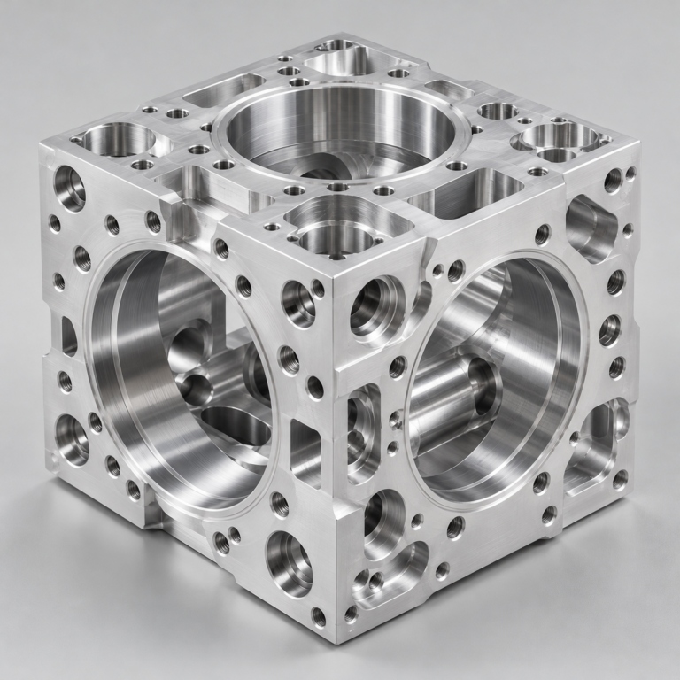
Precision parts for your tight tolerances and complex geometry.
Tooling and molding for your repeat plastic parts.
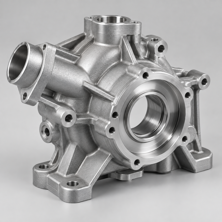
Metal casting options for your part and production volume.
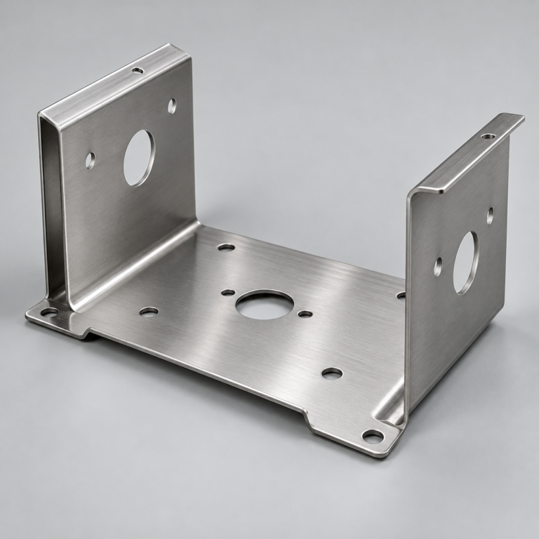
Cutting, forming and welding for your fabricated parts.
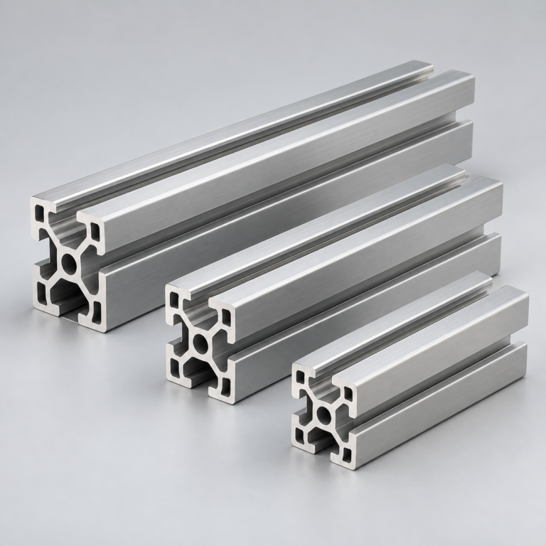
Custom profiles for your section, length and finish requirements.
Finishes for your appearance, corrosion and wear requirements.
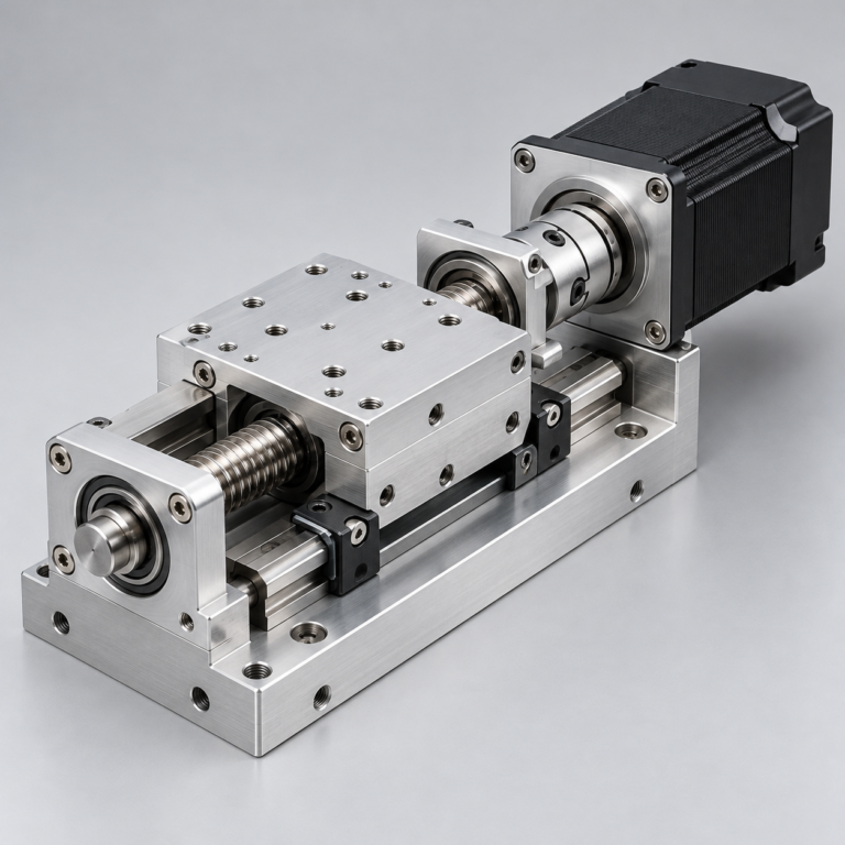
Sub-assemblies and final builds for your production program.
Production tooling built around your process and volume.
Prototype parts to check fit, function and design.
DFM, process planning and production support for your project.
Inspection, documentation, inventory and delivery planning for your program.
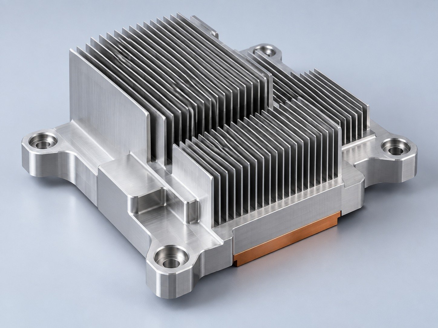
Choose air- or liquid-cooling components around your thermal and mechanical requirements.
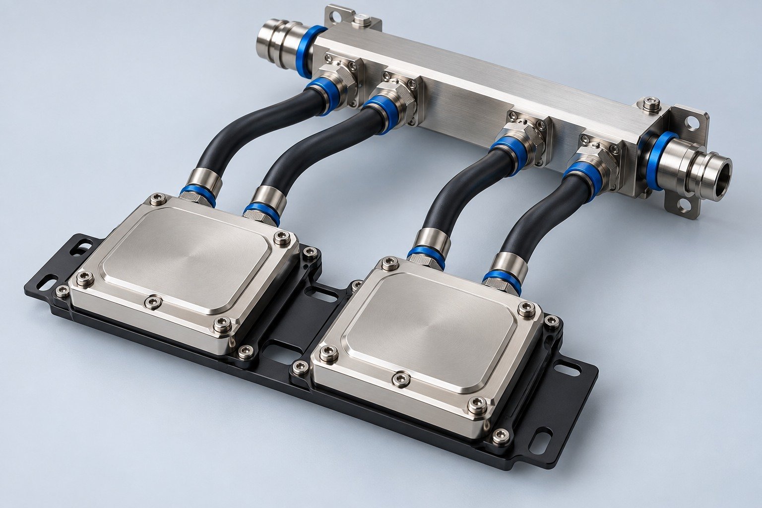
Manufacturing support for your cold plates, manifolds and cooling assemblies.
Find components for your power electronics, energy, laser and telecom application.
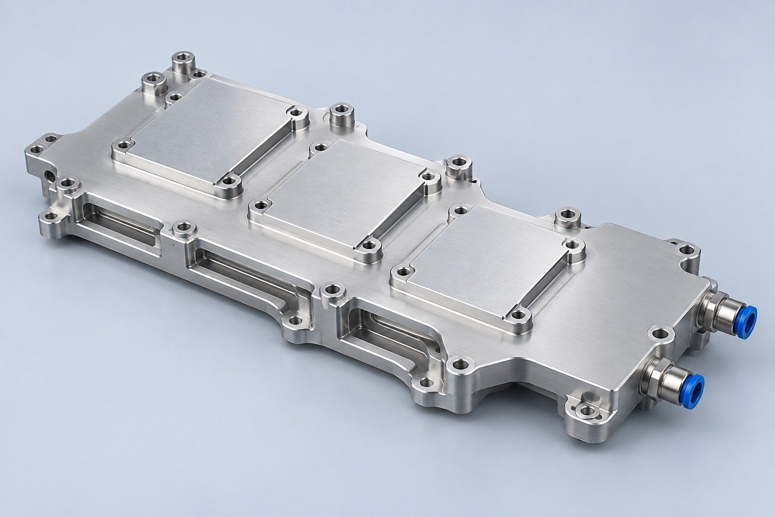
Components for your electronic systems.
Start with your functional and quality requirements.
Build around your operating environment.
From prototype to production, review material performance, manufacturability and cost for your part.
Review grade, temper and finish for your metal parts.
 AluminumStrength, weight and machining›
 Stainless SteelCorrosion and finish requirements›
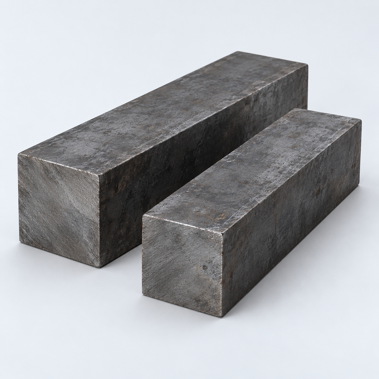 Carbon & Alloy SteelDiscuss grade and heat treatment›
 Tool SteelDiscuss tooling and wear needs›
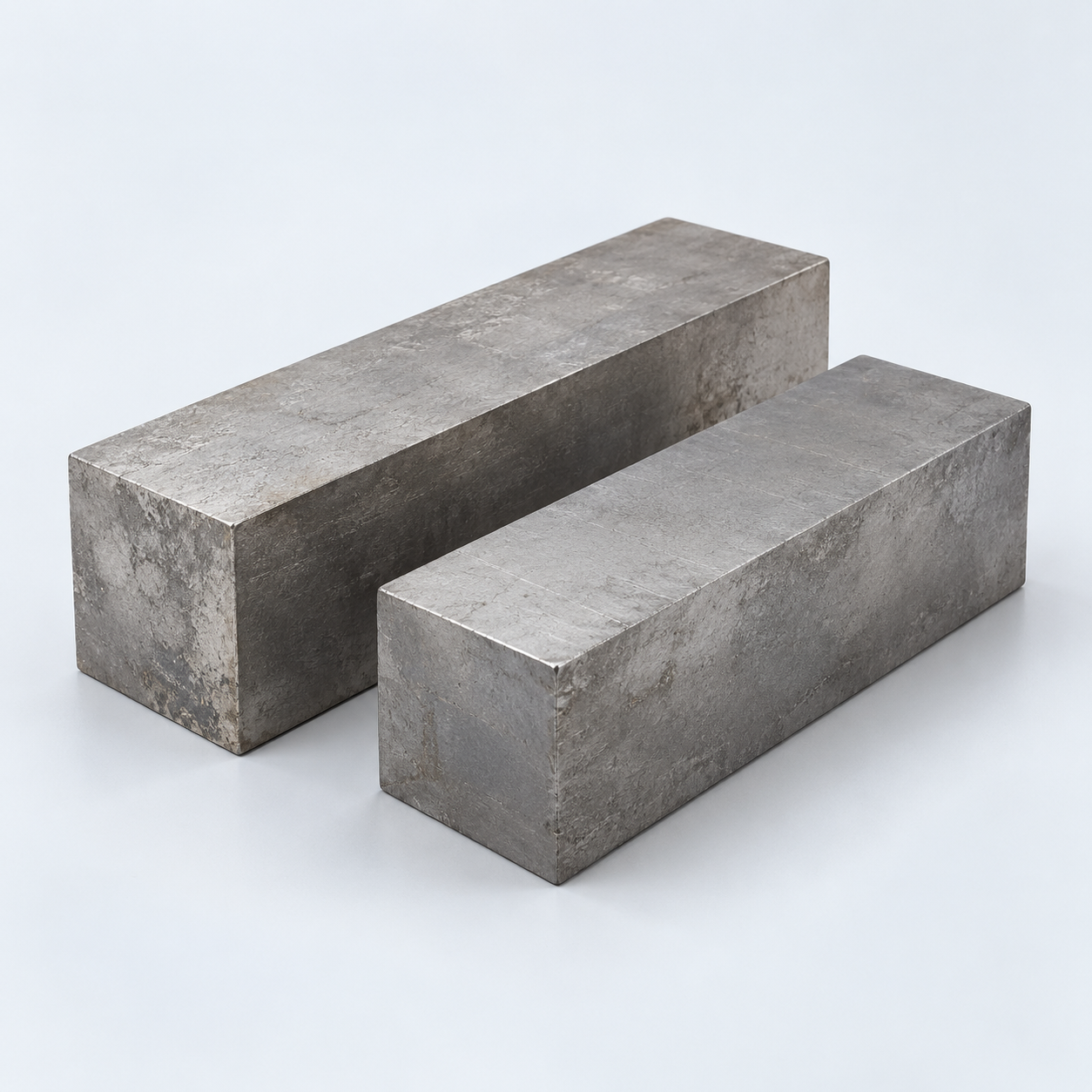 TitaniumReview grade and part geometry›
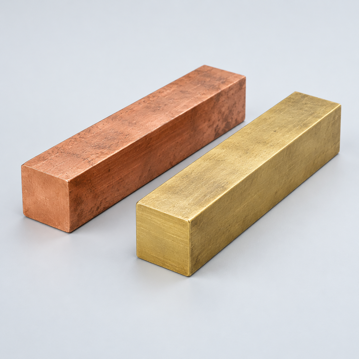 Copper & BrassDiscuss conductivity and machining›
Match your polymer to function, process and environment.
 ABSReview enclosure and molding needs›
 Polycarbonate (PC)Discuss clarity and impact needs›
 Nylon (PA)Review moisture and wear conditions›
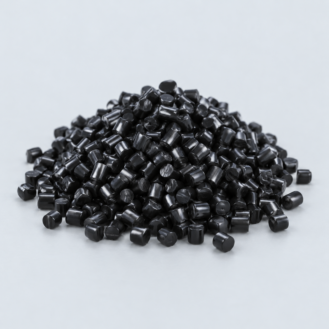 POM / AcetalReview fit and sliding features›
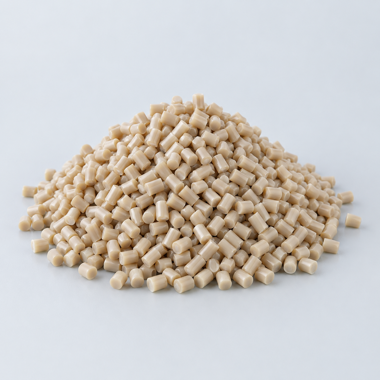 PEEKDiscuss operating conditions›
 PTFEReview friction and chemical exposure›
 ULTEM / PEIDiscuss thermal and electrical needs›
Confirm grade availability and application requirements.
 Silicone / LSRDiscuss flexible component needs›
 TPU / TPEReview flexibility and processing›
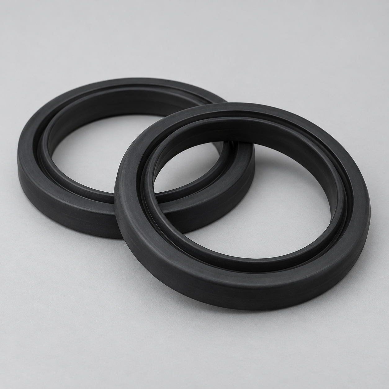 EPDMReview weathering and chemical exposure.›
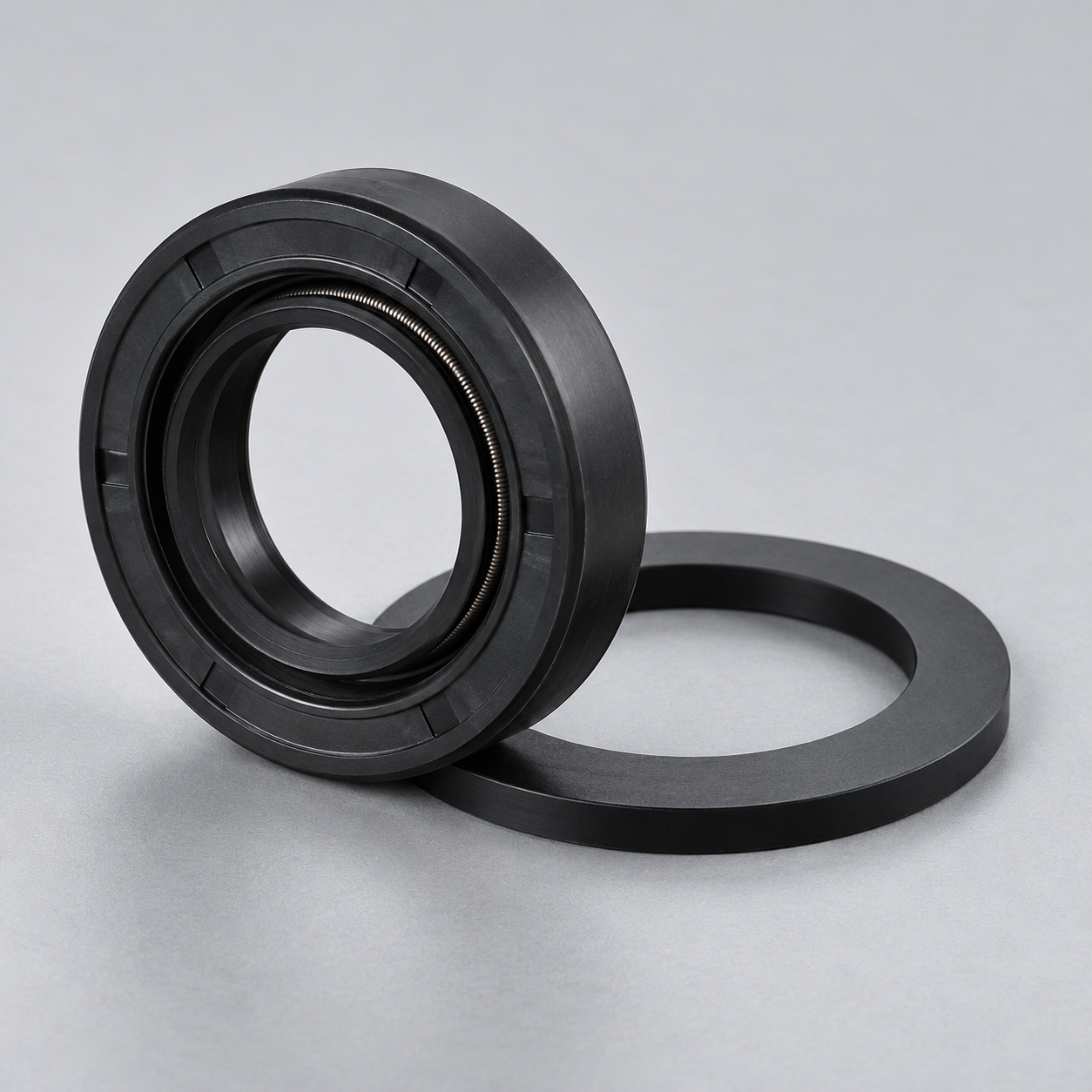 NBRReview oil and fuel exposure.›
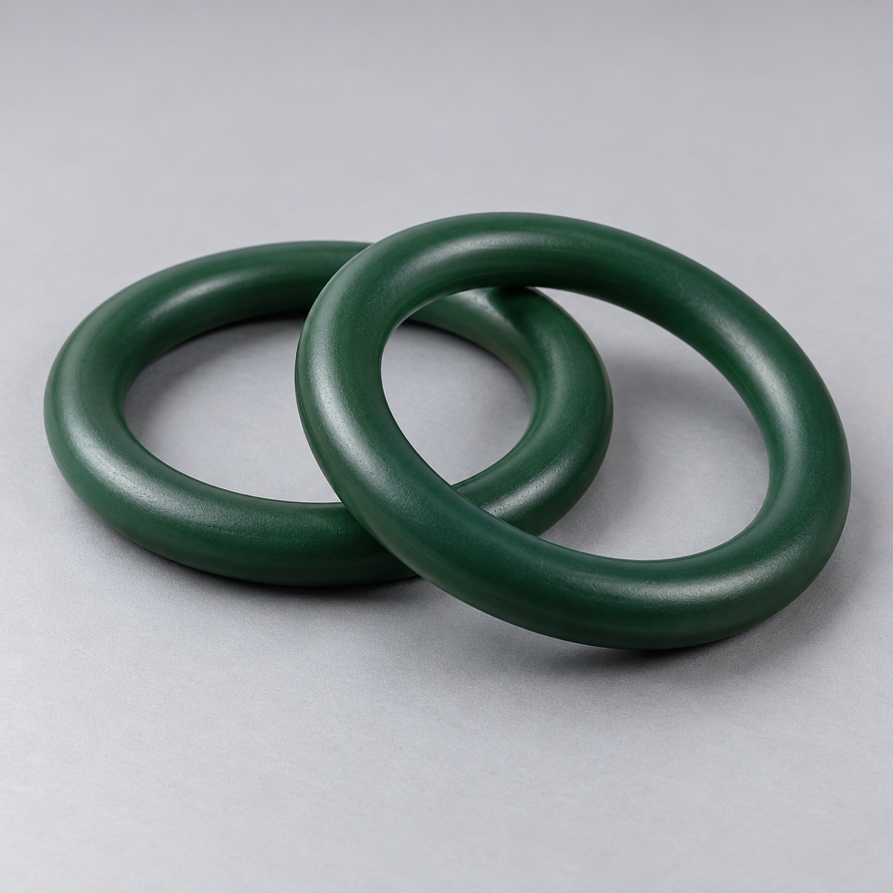 FKMReview temperature and chemical exposure.›
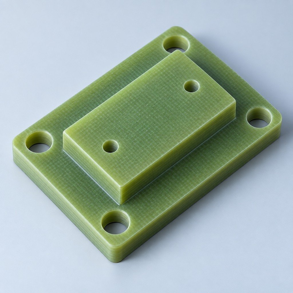 G10 / FR4Review insulation and laminate needs›
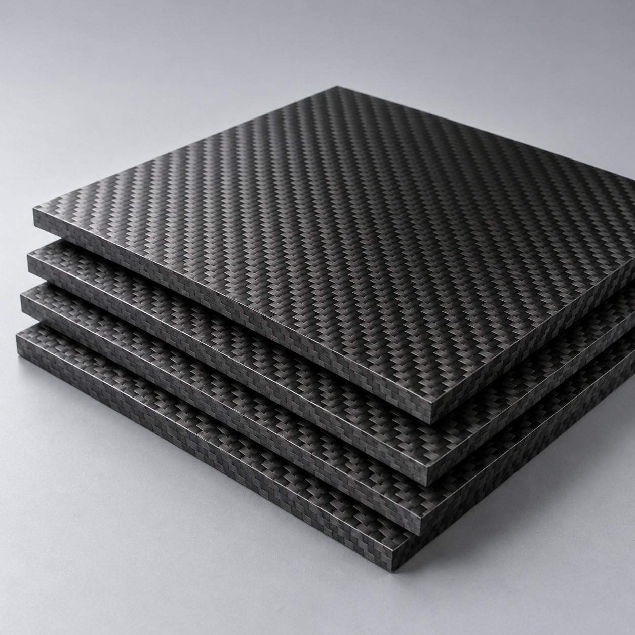 CompositesReview stiffness, weight and laminate.›Customer-Specified MaterialsConfirm your grade and requirements.›Other Specialty MaterialsDiscuss your application and grade.›
Practical guidance for your part geometry and material decisions.
Prepare your process, budget and sourcing questions.
Build your knowledge before production.
Learn who we are and how we operate.
Find our U.S. support team or start a conversation.
YOUR COMPONENTS. YOUR CONNECTIONS. YOUR FUNCTION.
Review your mechanical parts, purchased electrical components, wiring and acceptance as one build. Scope electromechanical assembly services around the function your receiving team needs, with clear component and test responsibilities.
1 approved build baseline: BOM, drawings, wiring and applicable configuration. Joining methods, electrical work, firmware and test resources are confirmed for your project.
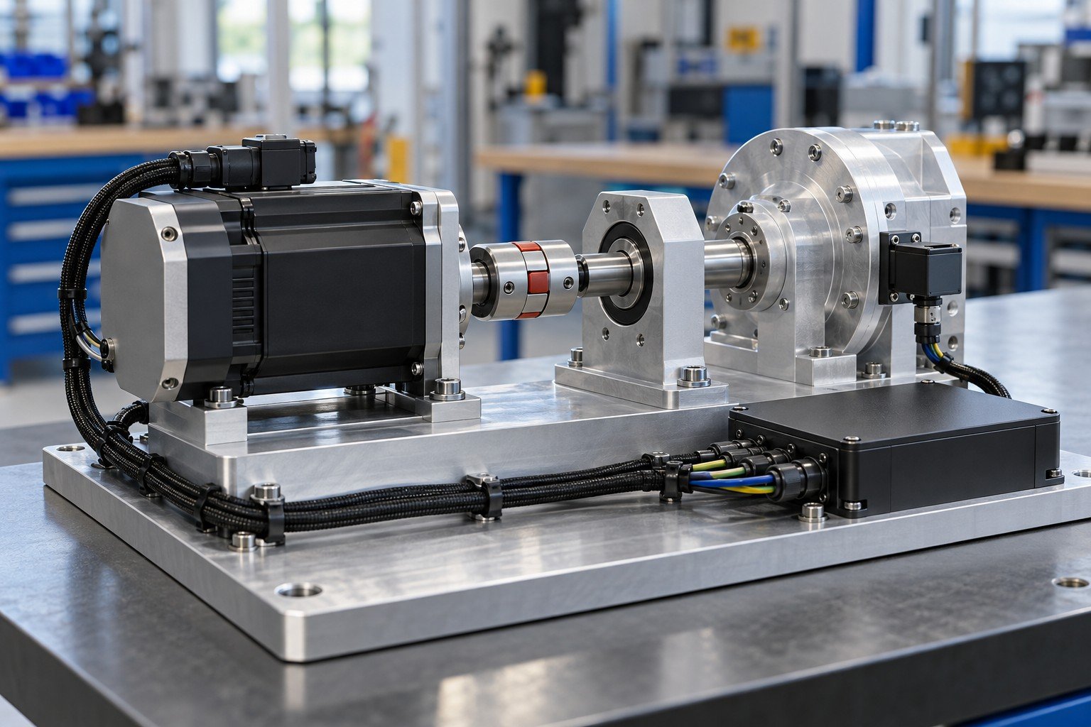
Module and delivery boundary
Approved parts and sources
Wiring map and routing
Method, limits and evidence
Identity and configuration
Close the gaps between mechanical drawings, electrical interfaces and delivered function.
Define the module, included electrical work and next integration step.
Assign every BOM item and approve substitutions before use.
Provide pin maps, routing, mounting and configuration requirements.
Distinguish connection checks, function and required safety testing.
Agree unit or lot identity, records and acceptance authority.
Use this electromechanical assembly process to define the handoffs your team can review.
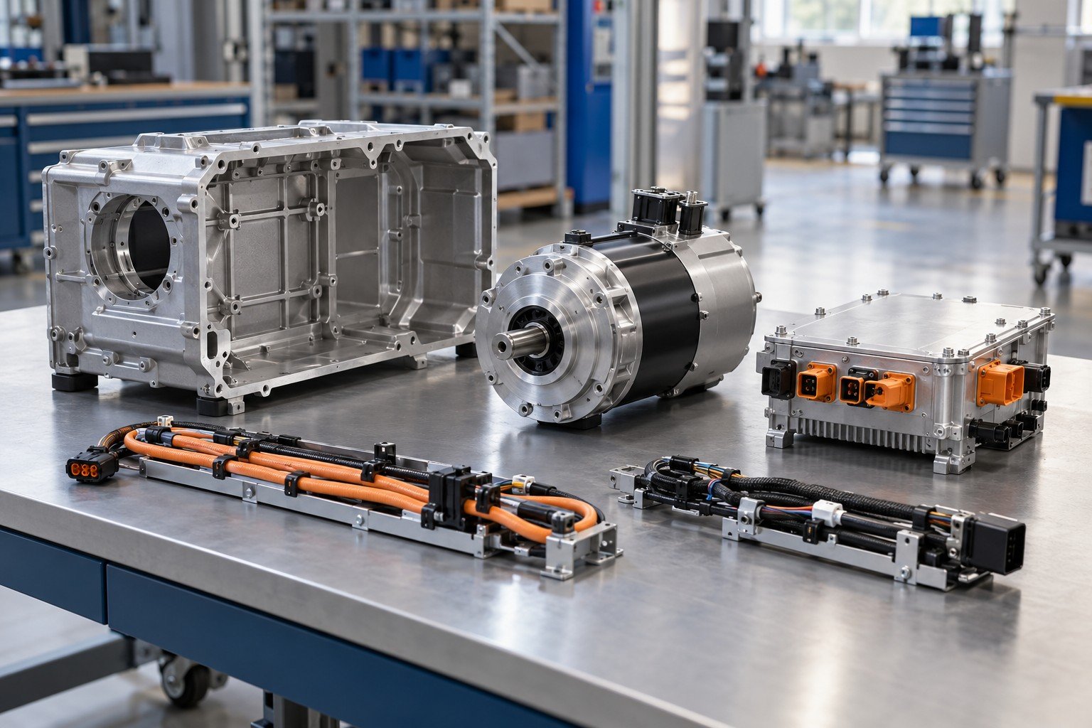
Align approved parts, quantities and document revisions before assembly.
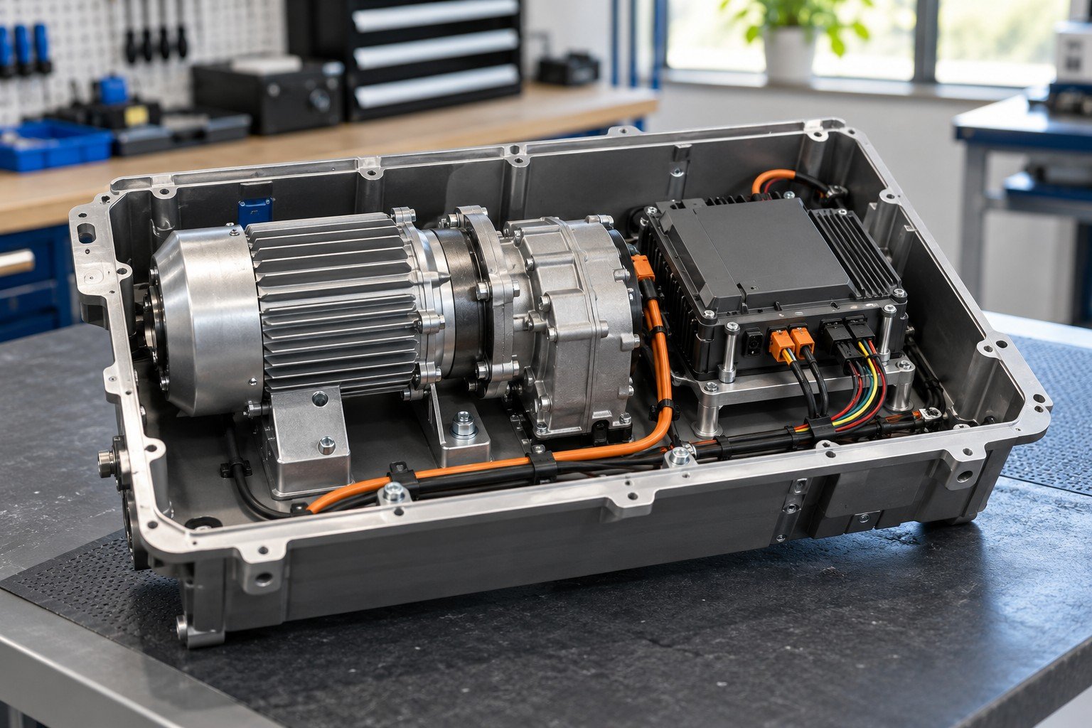
Install the mechanical and approved electrical items with access and protection defined.
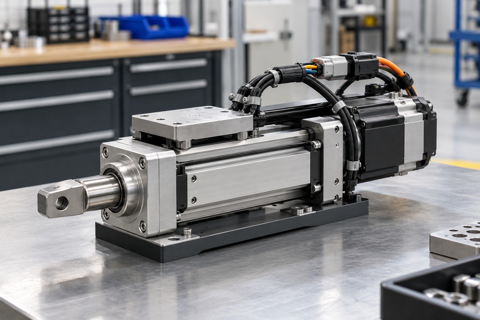
Follow the approved wiring, configuration and check procedures.
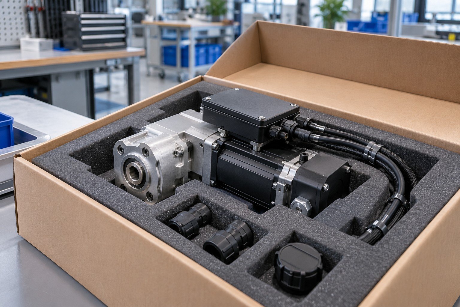
Link the accepted module to its records, revision and packing condition.
Review electromechanical integration services by module and function. Confirm the accepted operations and resources before committing components.
For contract electromechanical assembly, specify the mechanical interfaces, electrical connections and delivered operating state. A list of components alone does not define a working module.
| Your input | Assembly drawing, wiring diagram and required function. |
|---|---|
| Your decision | Agree included integration and verification steps. |
| Your baseline | Approved BOM, assembly drawing, wiring and applicable configuration revision. |
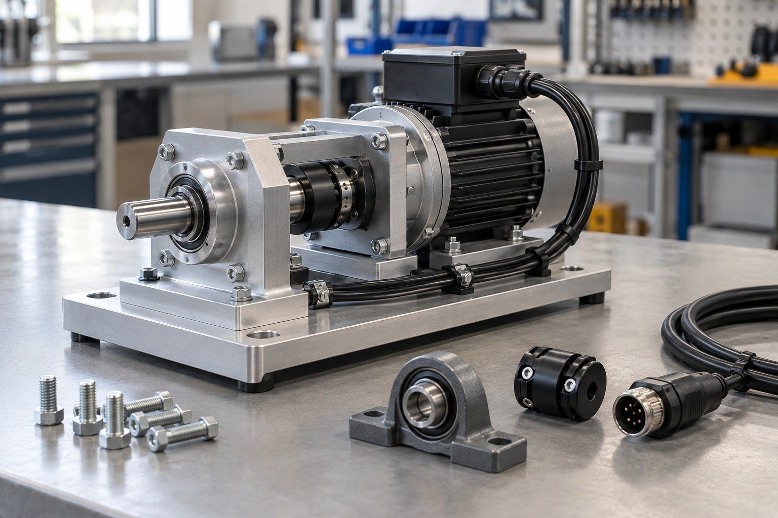
Your electromechanical bill of materials should identify approved part numbers, revisions and supply responsibility. An electrically similar component may have a different connector, mounting pattern or configuration.
| Your input | BOM, approved vendor list and supplied-item list. |
|---|---|
| Your decision | Control substitutions, shortages and incoming acceptance. |
| Your baseline | Approved BOM, assembly drawing, wiring and applicable configuration revision. |
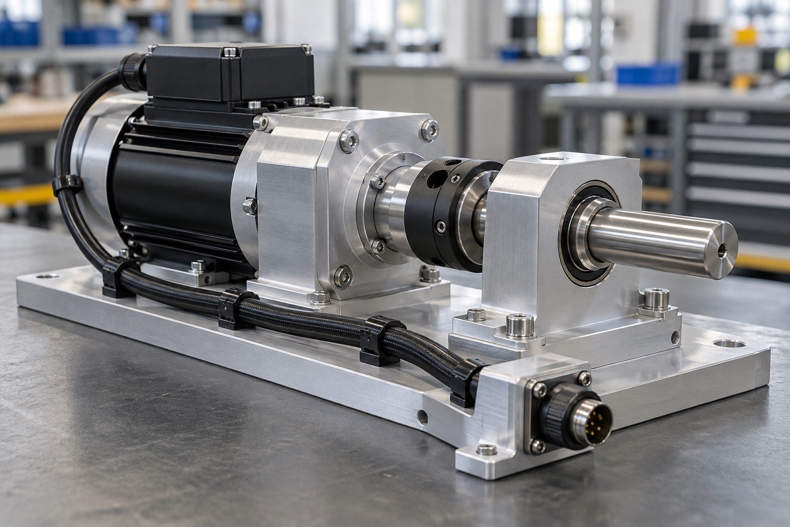
Electromechanical assembly work instructions need a clear sequence for mounting, fastening, wiring and checking. Review access before a cover hides a connection.
| Your input | Drawings, wiring schedule and assembly sequence. |
|---|---|
| Your decision | Define hold points, settings and workmanship criteria. |
| Your baseline | Approved BOM, assembly drawing, wiring and applicable configuration revision. |
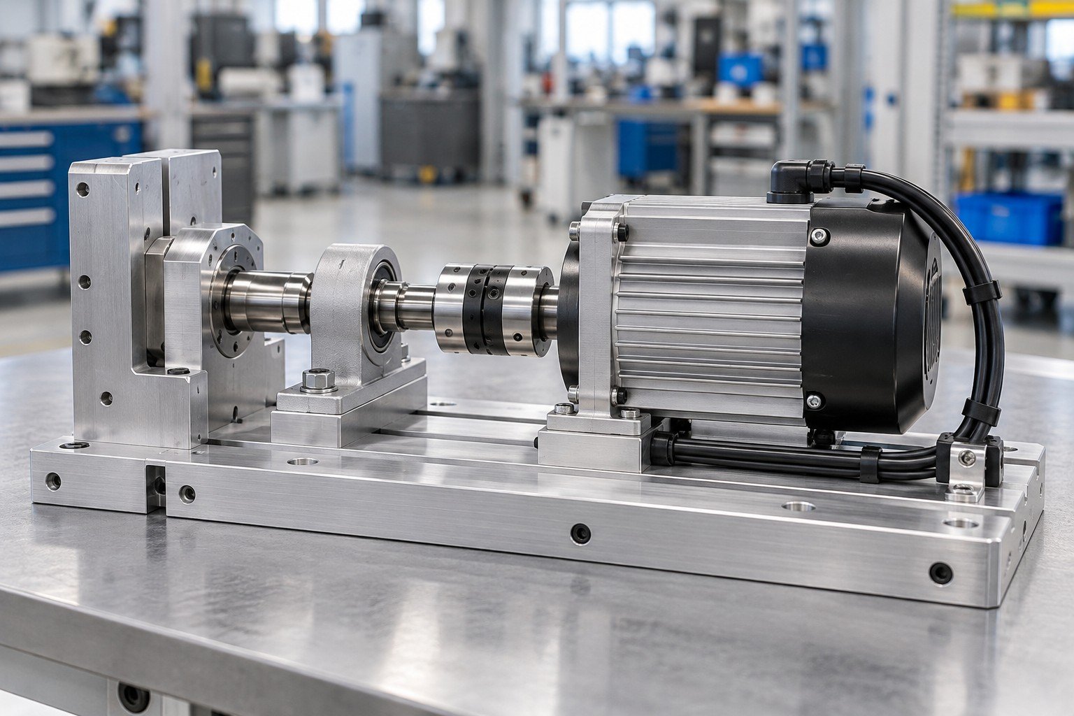
For custom electromechanical assembly, link the build revision and configuration to the agreed results. A power-on observation does not establish every operating requirement.
| Your input | Controlled check procedure and acceptance limits. |
|---|---|
| Your decision | Record results, deviations and approval authority. |
| Your baseline | Approved BOM, assembly drawing, wiring and applicable configuration revision. |
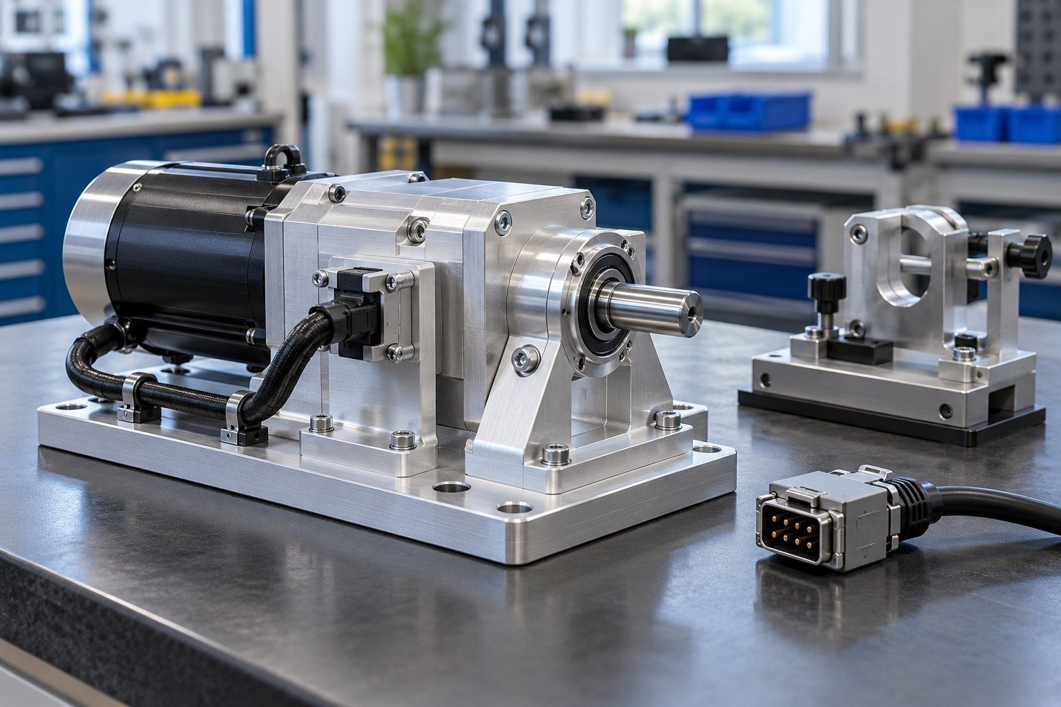
Enclosure integration services connect housings, purchased electrical items, brackets and wiring around your delivered scope. Identify interfaces to equipment assembled elsewhere.
| Your input | Enclosure CAD, component layout and interface definitions. |
|---|---|
| Your decision | Confirm included assembly and any excluded electrical work. |
| Your baseline | Approved BOM, assembly drawing, wiring and applicable configuration revision. |
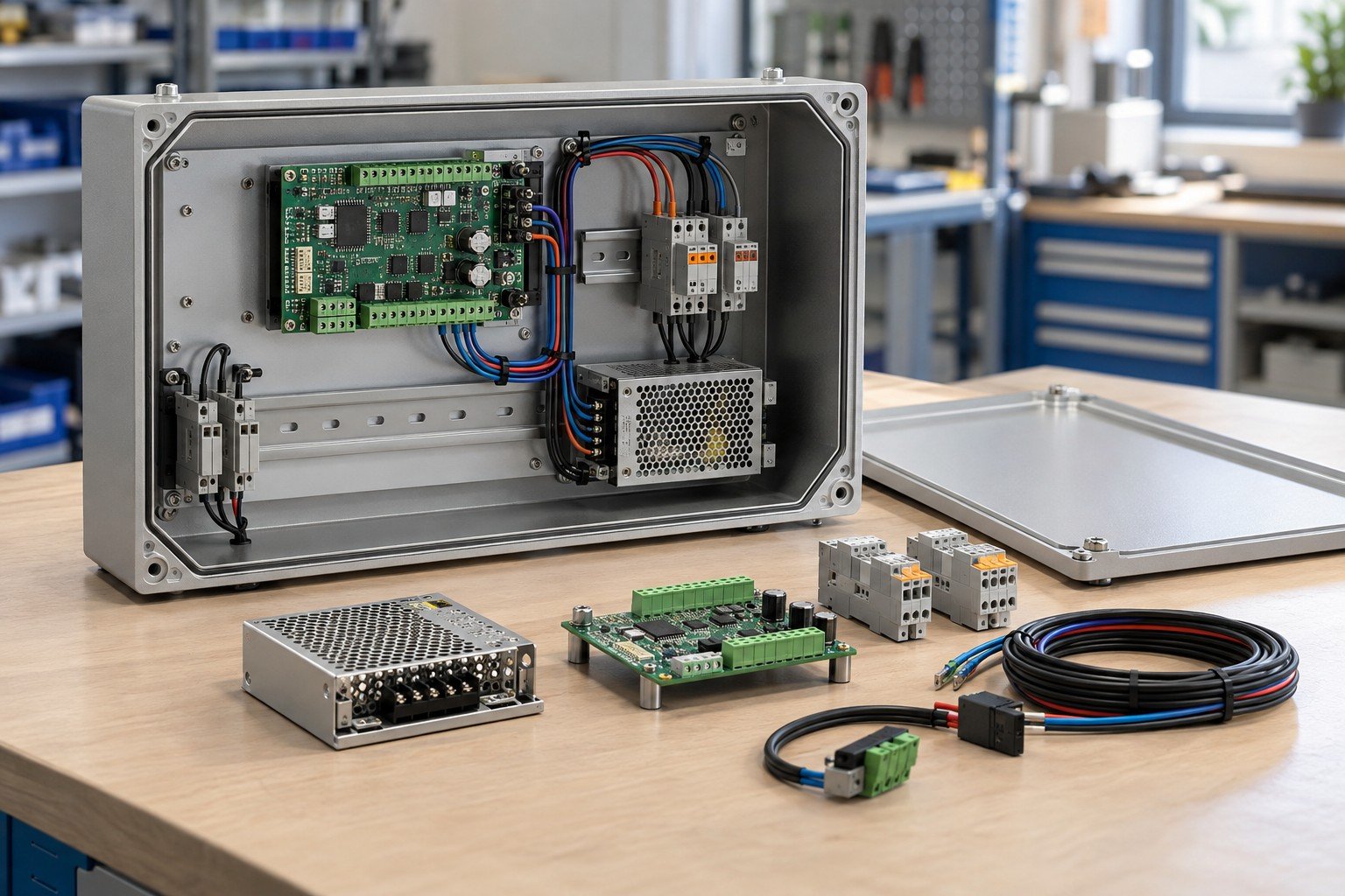
Electronic enclosure assembly needs access for connectors, fasteners and service. Define clearance and protection requirements from the approved product design.
| Your input | Component envelopes, cable exits and protected surfaces. |
|---|---|
| Your decision | Review routing, strain relief and service access. |
| Your baseline | Approved BOM, assembly drawing, wiring and applicable configuration revision. |
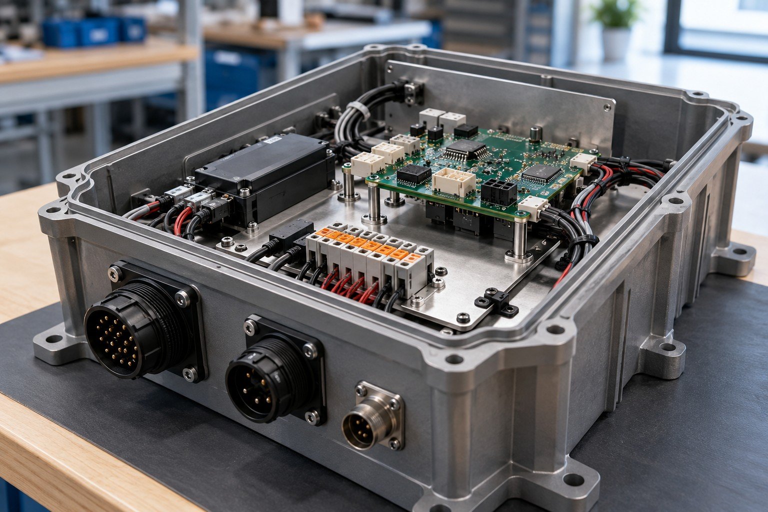
Box build assembly services require a component layout, wiring information and controlled mounting details. PCBA fabrication, harness production and enclosure fabrication are separate supply responsibilities.
| Your input | Approved layout, wiring diagram and purchased assembly specifications. |
|---|---|
| Your decision | Agree sourced versus supplied items and assembly sequence. |
| Your baseline | Approved BOM, assembly drawing, wiring and applicable configuration revision. |
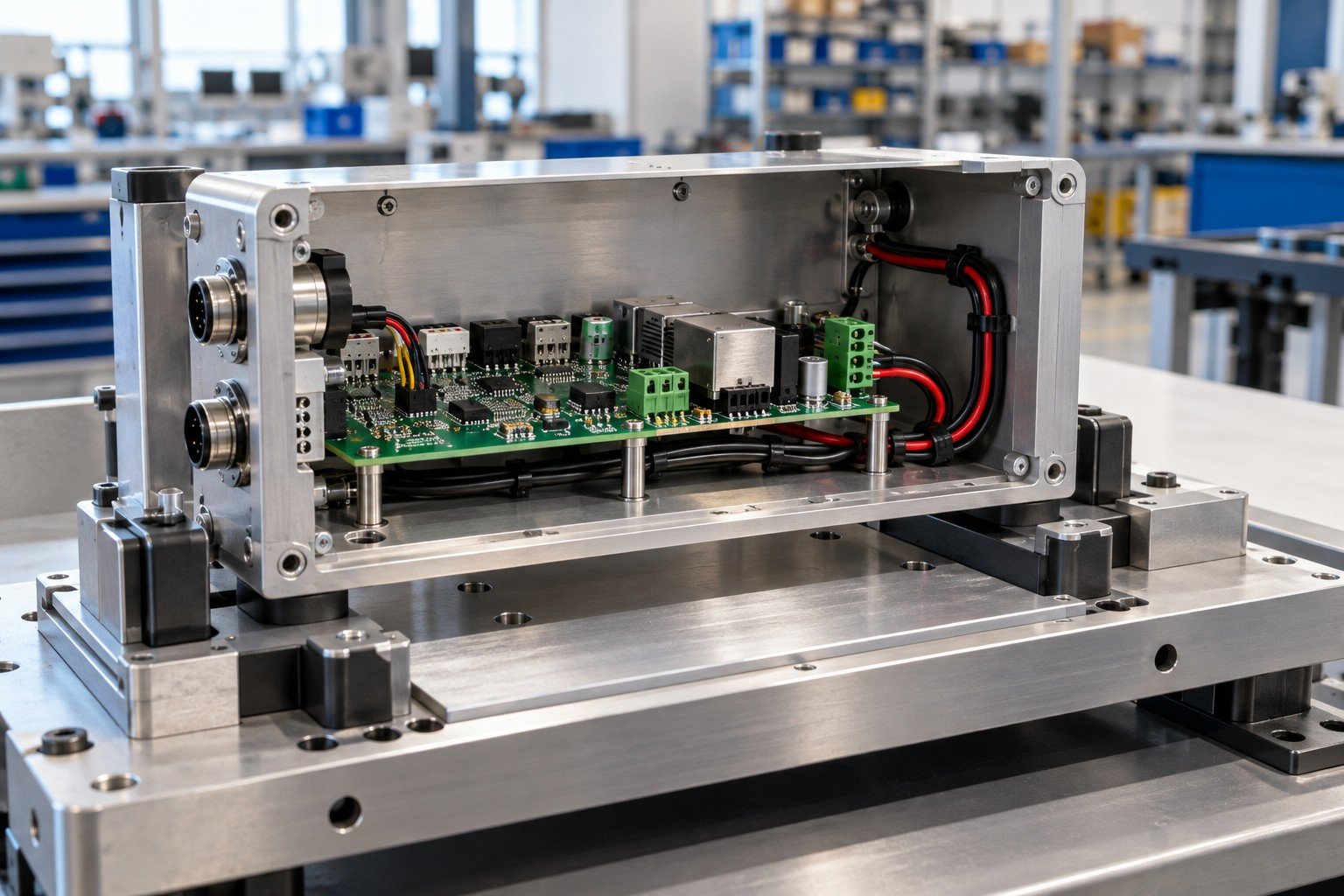
Confirm mounting, connector seating, routing and applicable checks before final closure. Environmental, ingress or electrical safety testing requires an explicitly agreed method and resources.
| Your input | Inspection points, closure sequence and test scope. |
|---|---|
| Your decision | Record required evidence without implying product certification. |
| Your baseline | Approved BOM, assembly drawing, wiring and applicable configuration revision. |
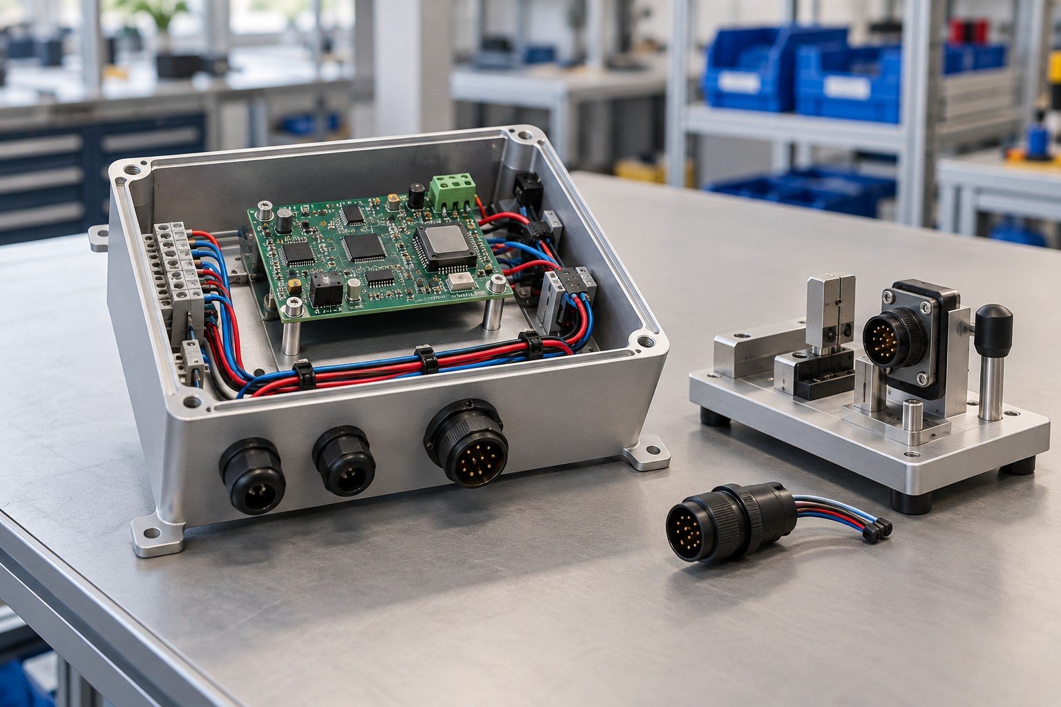
Wiring and mechanical assembly must use the approved pin map, connector identities and route. Wire color by itself is not a complete connection specification.
| Your input | Wiring diagram, connector schedule and harness drawing. |
|---|---|
| Your decision | Agree component identity and installation boundaries. |
| Your baseline | Approved BOM, assembly drawing, wiring and applicable configuration revision. |
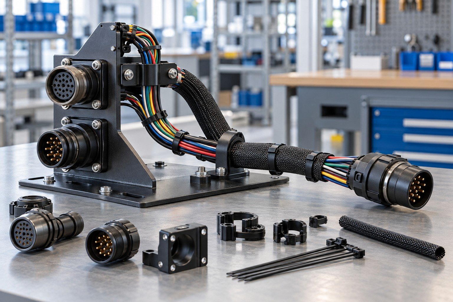
Distinguish installation of an approved purchased harness from manufacture of the harness itself. Cable construction, terminations and any workmanship standard must be confirmed for the actual scope.
| Your input | Approved harness part number and supplier requirements. |
|---|---|
| Your decision | Assign procurement, incoming checks and permitted rework. |
| Your baseline | Approved BOM, assembly drawing, wiring and applicable configuration revision. |
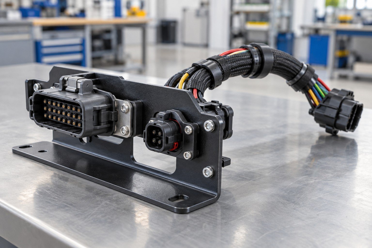
Review clips, protective sleeves, bend requirements and strain relief against the supplied cable and product design. Moving modules need a defined travel envelope.
| Your input | Cable supplier guidance, movement and mounting geometry. |
|---|---|
| Your decision | Agree route, support and protected contact points. |
| Your baseline | Approved BOM, assembly drawing, wiring and applicable configuration revision. |
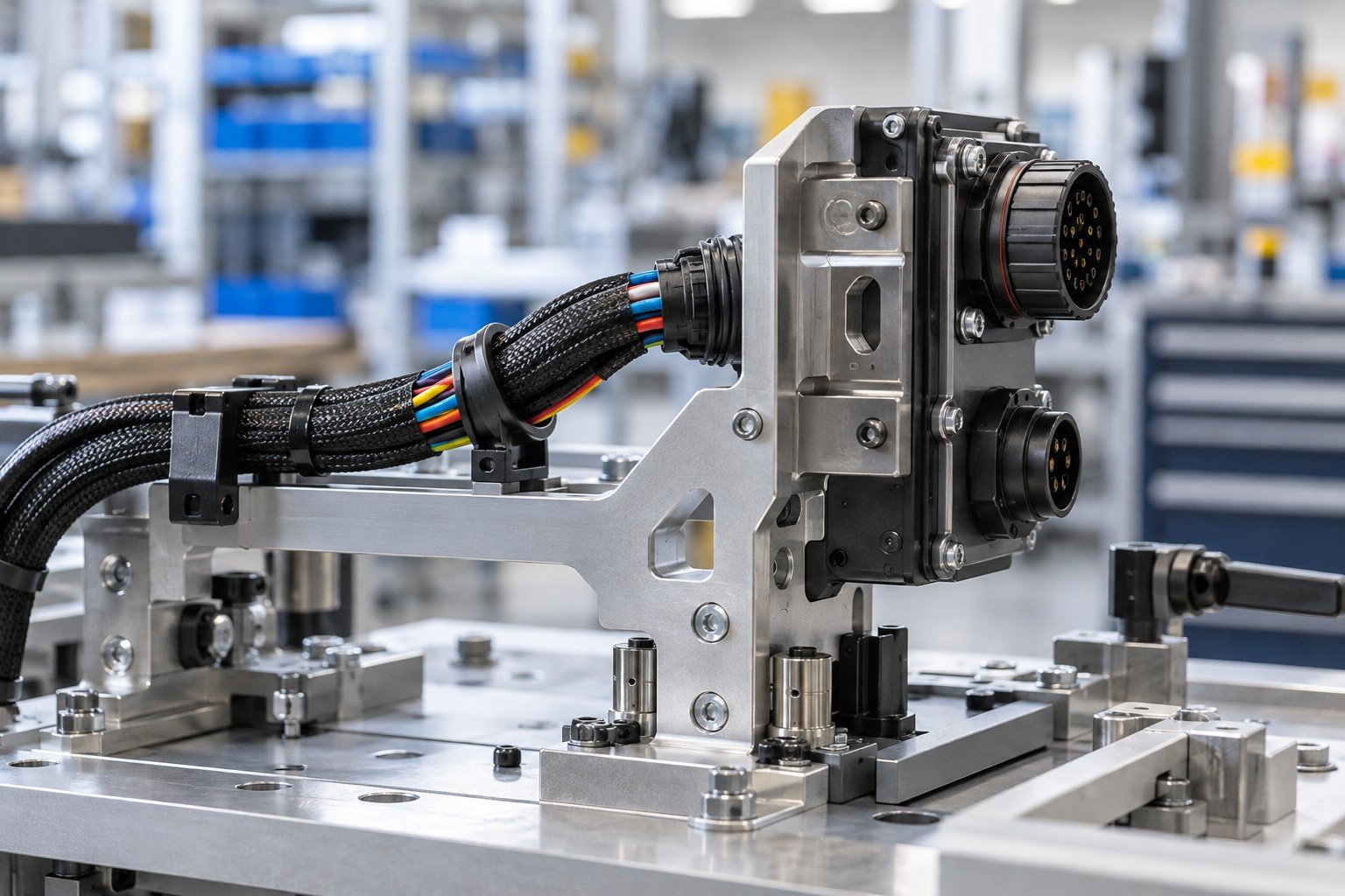
Continuity checks verify specified electrical paths under an agreed procedure. They do not establish operating performance, insulation integrity or safety certification by themselves.
| Your input | Pin map, test method and pass/fail criteria. |
|---|---|
| Your decision | Confirm equipment, coverage, records and reaction to failure. |
| Your baseline | Approved BOM, assembly drawing, wiring and applicable configuration revision. |
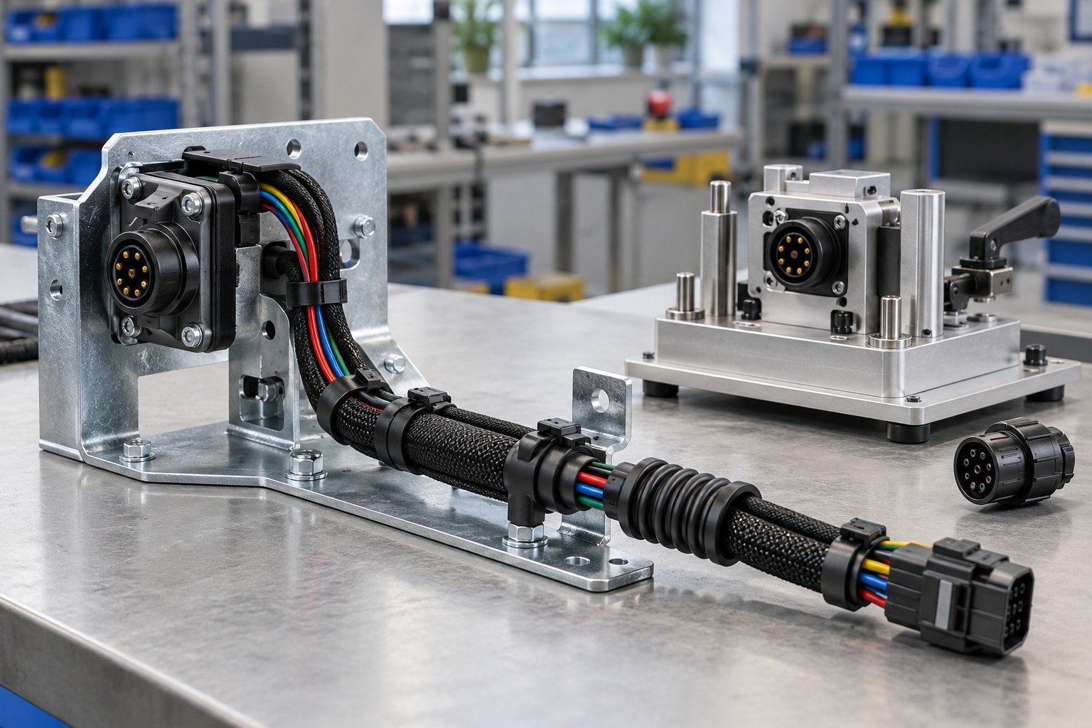
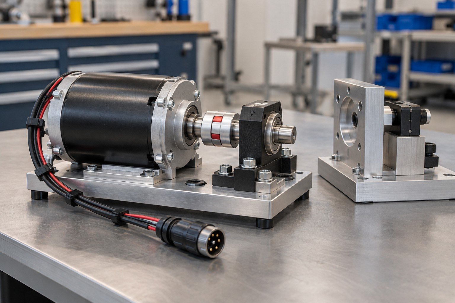
Motor assembly services on this page concern project review for installing approved motors into mechanical modules. Motor winding, motor design and motor certification are not assumed.
| Your input | Motor part number, mounting drawing and interface specification. |
|---|---|
| Your decision | Confirm mechanical installation and electrical connection scope. |
| Your baseline | Approved BOM, assembly drawing, wiring and applicable configuration revision. |
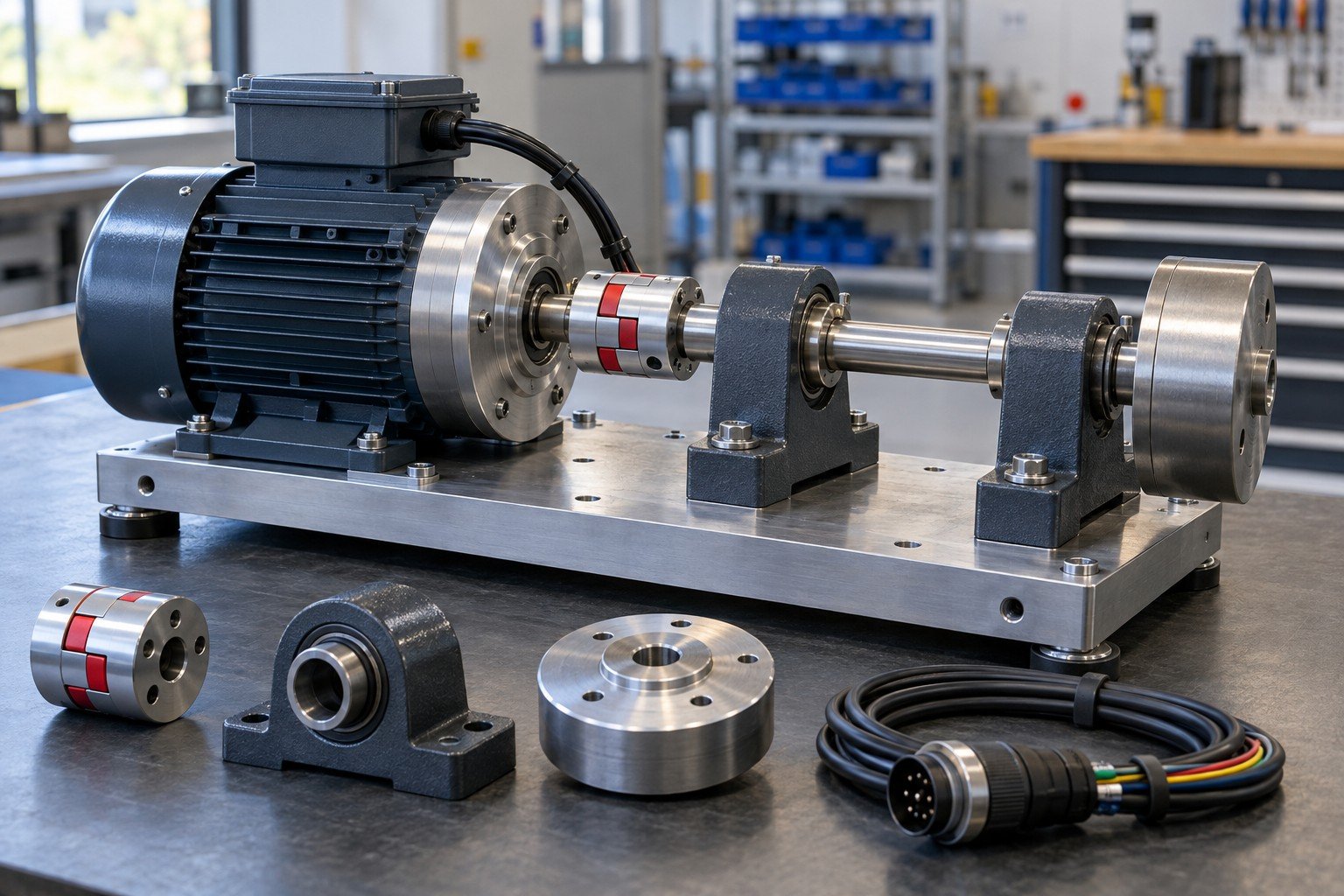
Check coupling, mounts, shaft support and fastener access against the approved design. Do not use the coupling to pull an incorrectly located motor into position.
| Your input | Alignment requirements, datums and coupling instructions. |
|---|---|
| Your decision | Agree locating fixtures and applicable measurements. |
| Your baseline | Approved BOM, assembly drawing, wiring and applicable configuration revision. |
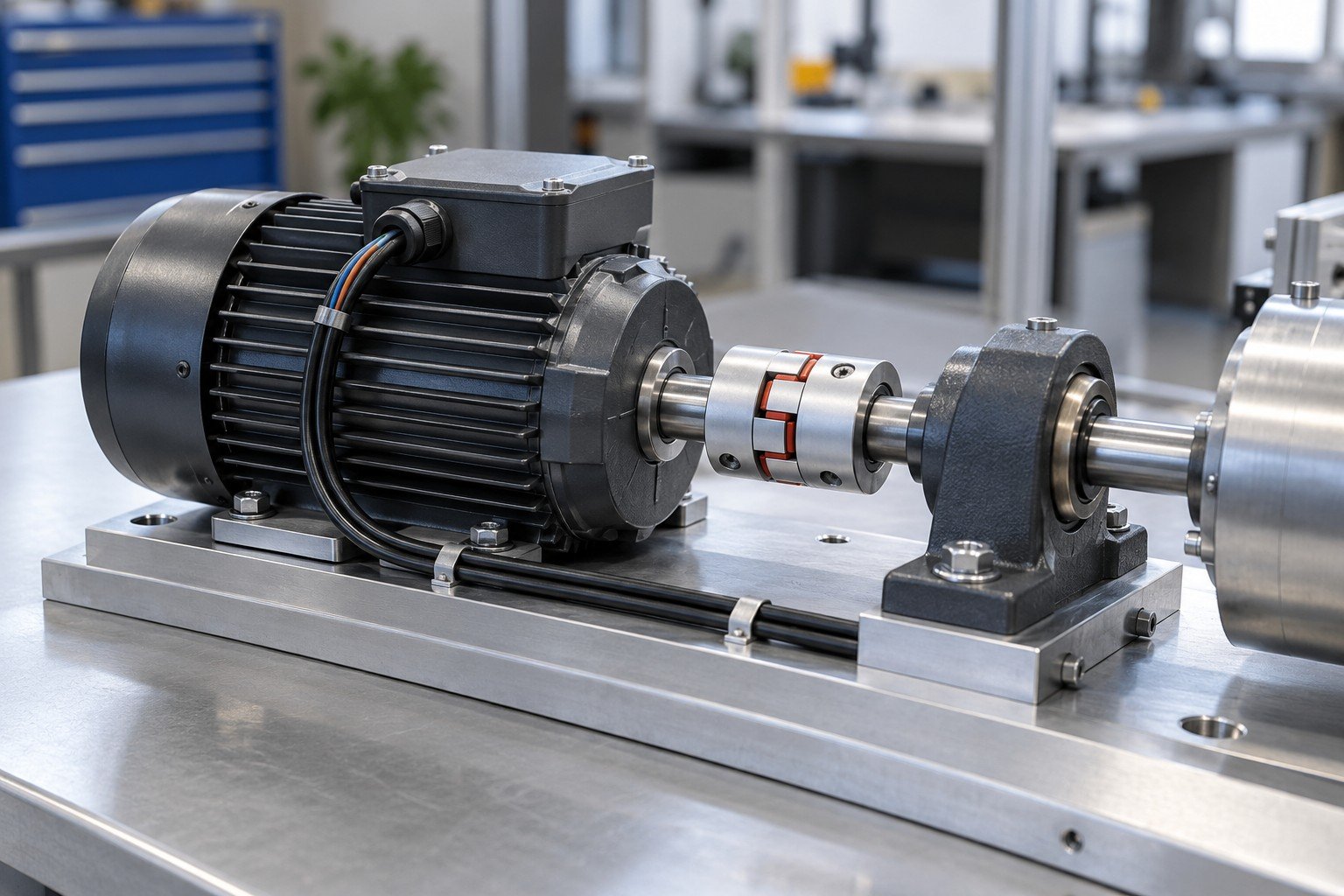
Define motor connections, polarity or phase mapping as applicable, and any approved drive settings. Software loading or tuning needs a separately confirmed procedure and authorization.
| Your input | Wiring map, configuration revision and required settings. |
|---|---|
| Your decision | Assign configuration responsibility and verification. |
| Your baseline | Approved BOM, assembly drawing, wiring and applicable configuration revision. |
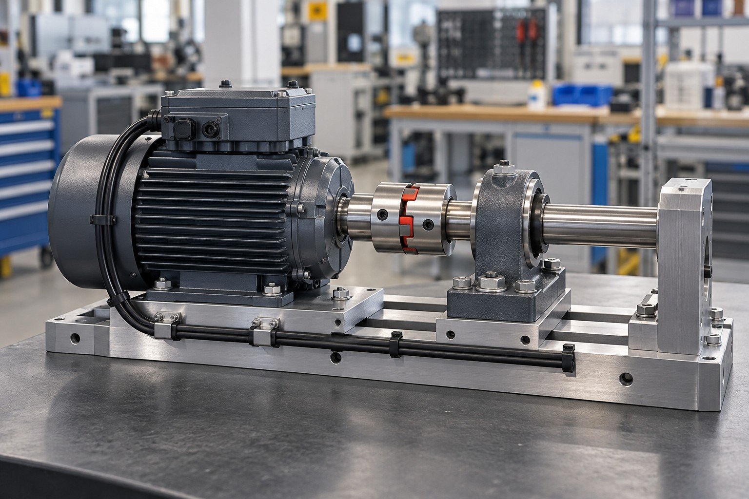
Electromechanical functional testing needs stated operating conditions, limits and safe test arrangements. No-load motion alone does not establish rated-load, endurance or product safety acceptance.
| Your input | Function, limits, test fixture and required evidence. |
|---|---|
| Your decision | Agree feasible checks, resources and release responsibilities. |
| Your baseline | Approved BOM, assembly drawing, wiring and applicable configuration revision. |
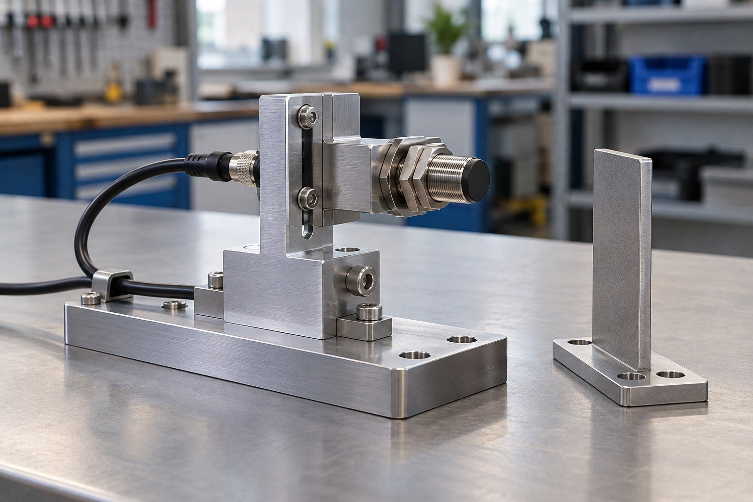
Sensor assembly services need the approved sensor model, mounting geometry and target conditions. A tidy installation does not prove the required detection performance.
| Your input | Sensor datasheet, target and installation drawing. |
|---|---|
| Your decision | Confirm positioning and functional acceptance conditions. |
| Your baseline | Approved BOM, assembly drawing, wiring and applicable configuration revision. |
Review connector keying, pinout, supply and output interface using the approved documents. Component substitution requires both mechanical and electrical review.
| Your input | Part number, wiring diagram and interface requirements. |
|---|---|
| Your decision | Approve component changes before installation. |
| Your baseline | Approved BOM, assembly drawing, wiring and applicable configuration revision. |
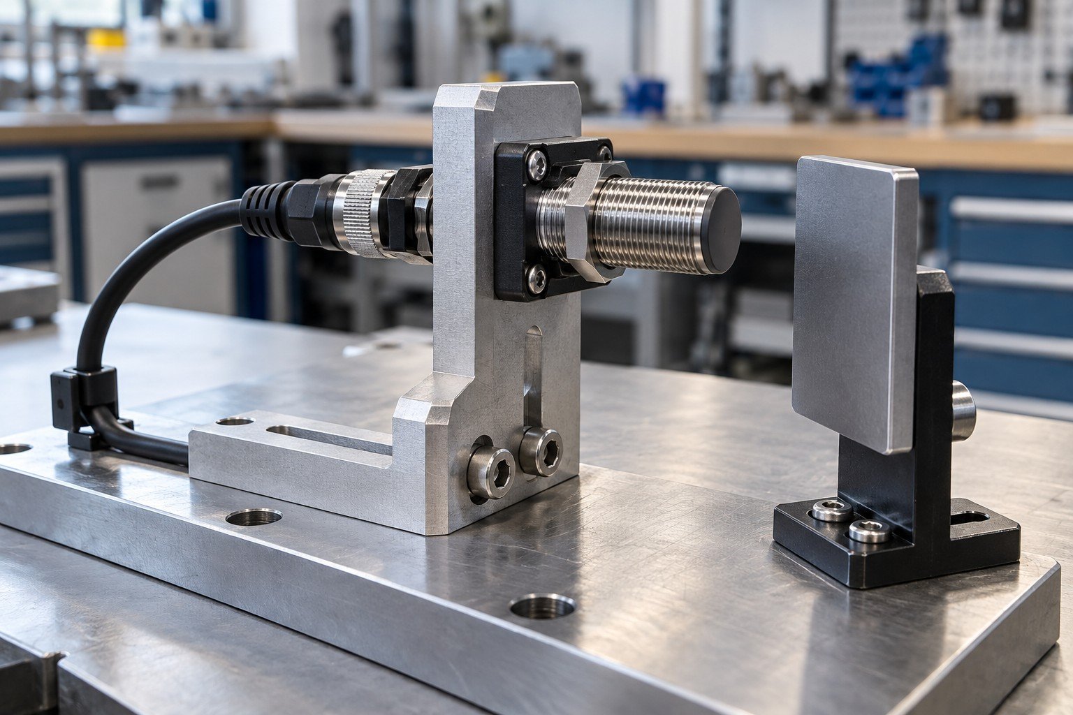
Check mounting adjustment, cable support and service access in the assembled condition. Record any setting that affects operation.
| Your input | Adjustment range, locking details and cable route. |
|---|---|
| Your decision | Define setup sequence and recorded settings. |
| Your baseline | Approved BOM, assembly drawing, wiring and applicable configuration revision. |

Agree the relevant target, position and operating conditions for verification. Calibration or certified measurement capability is a separate requirement, not implied by assembly.
| Your input | Check procedure, acceptance limits and record format. |
|---|---|
| Your decision | Confirm test resources and any qualification outside the build scope. |
| Your baseline | Approved BOM, assembly drawing, wiring and applicable configuration revision. |
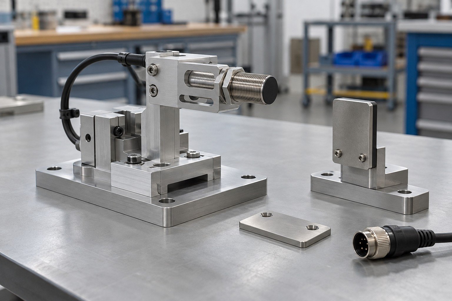
Actuator assembly services need the approved actuator, mounting arrangement, travel and interfaces. Include surrounding equipment that can constrain movement.
| Your input | Actuator model, mount drawings and required motion. |
|---|---|
| Your decision | Define integration boundary and operating envelope. |
| Your baseline | Approved BOM, assembly drawing, wiring and applicable configuration revision. |
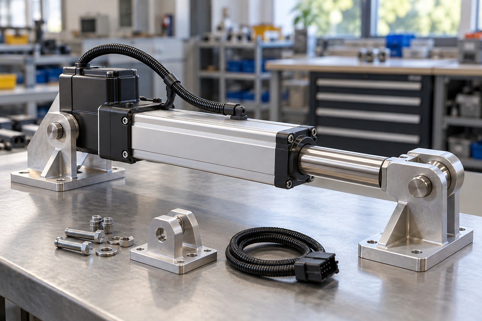
Review interference, cable movement and pinch or trapping risks under your product design process. Assembly does not replace product safety engineering.
| Your input | Travel envelope, load direction and cable limits. |
|---|---|
| Your decision | Identify design decisions and checks before build release. |
| Your baseline | Approved BOM, assembly drawing, wiring and applicable configuration revision. |
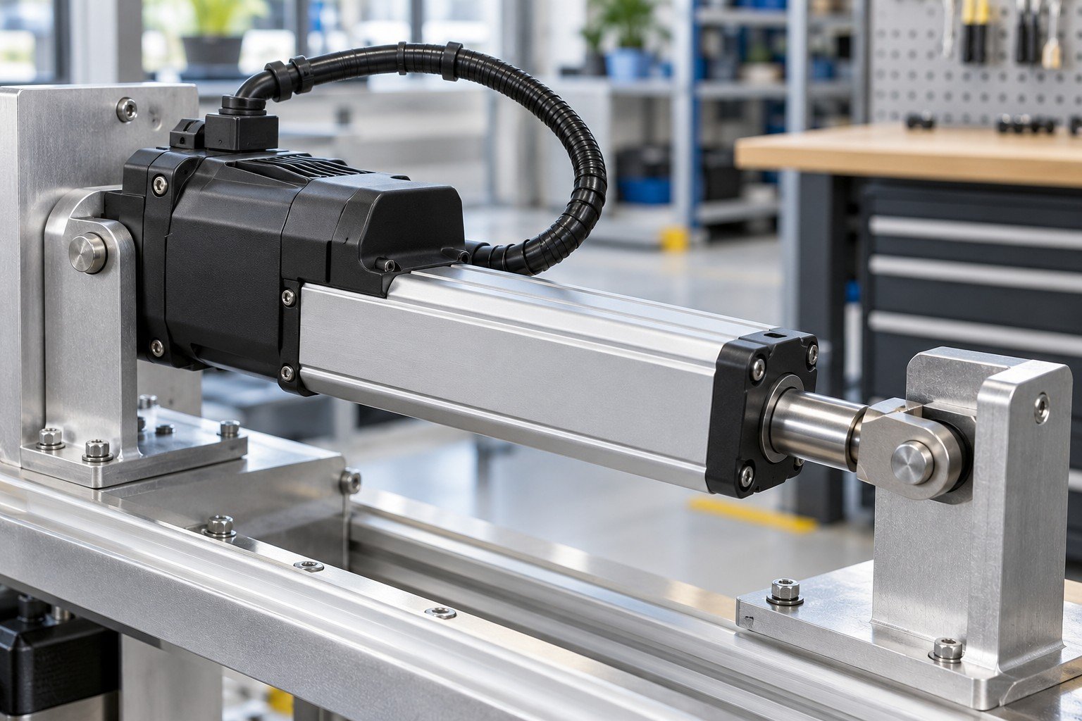
If limits, feedback or drive settings are part of the project, identify who supplies and approves them. Avoid undocumented settings becoming the repeat-build standard.
| Your input | Approved configuration and setup procedure. |
|---|---|
| Your decision | Assign authorization and record the installed version. |
| Your baseline | Approved BOM, assembly drawing, wiring and applicable configuration revision. |

Confirm travel or other specified checks under defined conditions. Load capacity, duty cycle and safety functions need their own validation requirements.
| Your input | Test conditions, limits and evidence requirements. |
|---|---|
| Your decision | Separate assembly checks from product qualification. |
| Your baseline | Approved BOM, assembly drawing, wiring and applicable configuration revision. |
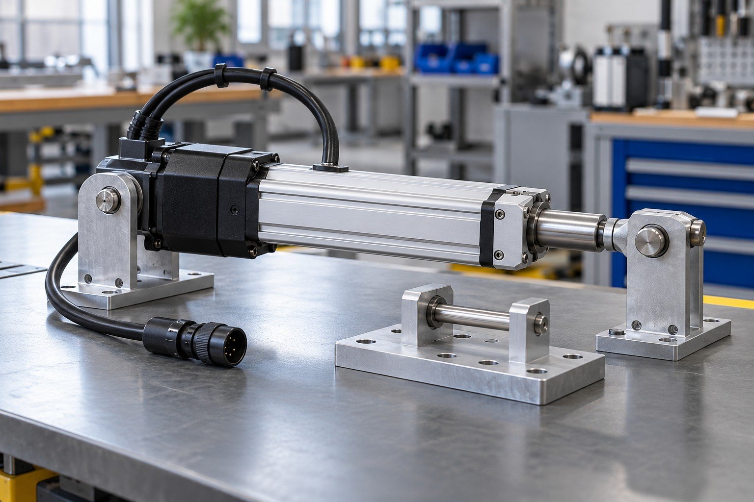
Electromechanical prototype assembly should have a defined learning goal: fit, connection access, sequence or agreed function. Record changes before quoting the repeat build.
| Your input | Prototype quantity, open decisions and required evidence. |
|---|---|
| Your decision | Agree the trial scope and approval milestones. |
| Your baseline | Approved BOM, assembly drawing, wiring and applicable configuration revision. |
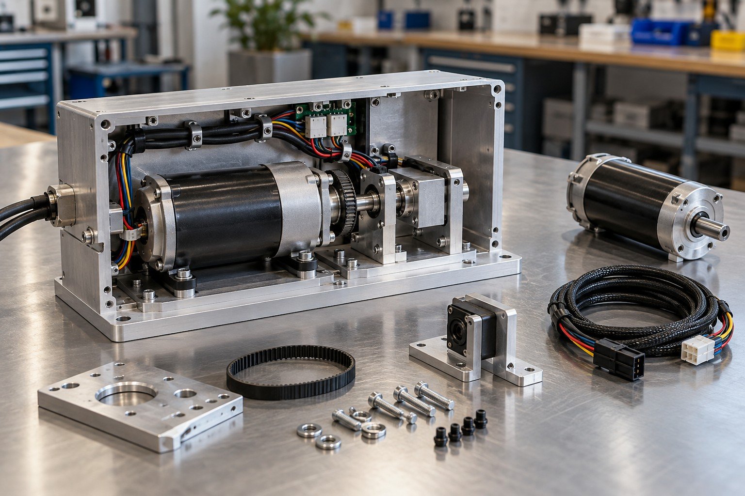
Turnkey electromechanical assembly means an agreed procurement and build scope. It does not automatically include product design, all component manufacture or certification.
| Your input | BOM, approved sources and customer-supplied items. |
|---|---|
| Your decision | Define shortages, substitutions, excess material and ownership. |
| Your baseline | Approved BOM, assembly drawing, wiring and applicable configuration revision. |
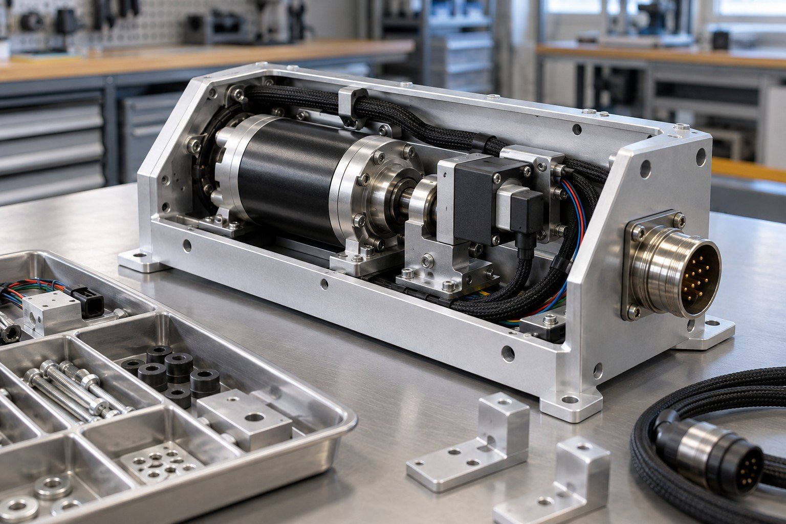
Low volume electromechanical assembly and repeat orders still need controlled drawings, wiring, work instructions and applicable firmware or settings.
| Your input | Accepted revisions, configuration and change process. |
|---|---|
| Your decision | Record the baseline and approve changes before use. |
| Your baseline | Approved BOM, assembly drawing, wiring and applicable configuration revision. |
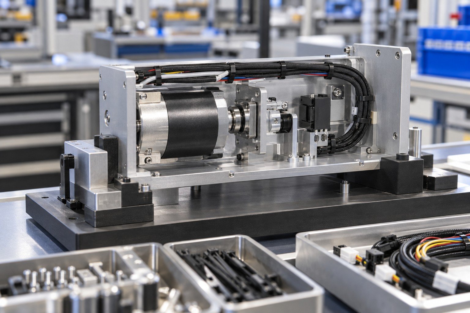
Electromechanical assembly traceability links the agreed unit or lot identity to components, build revision, configuration and check results. Define the required detail in your scope.
| Your input | Identification, records and receiving requirements. |
|---|---|
| Your decision | Agree retention, deviations and shipment release. |
| Your baseline | Approved BOM, assembly drawing, wiring and applicable configuration revision. |
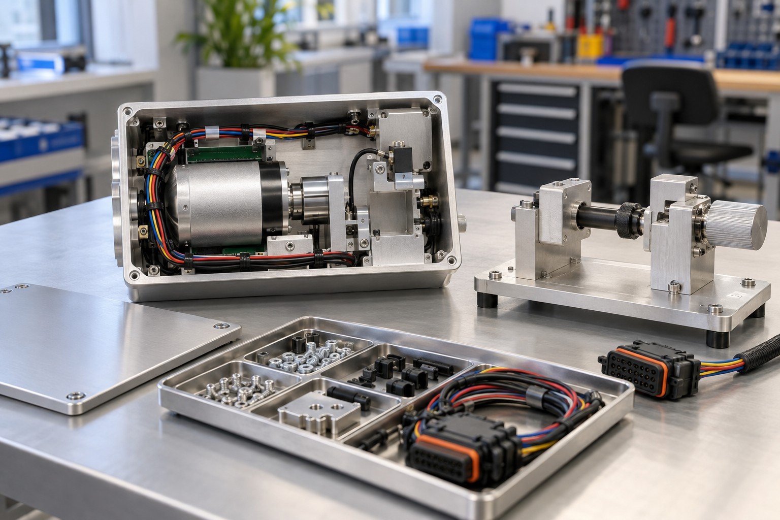
Mark your connection details, moving interfaces and acceptance limits before the build is released.
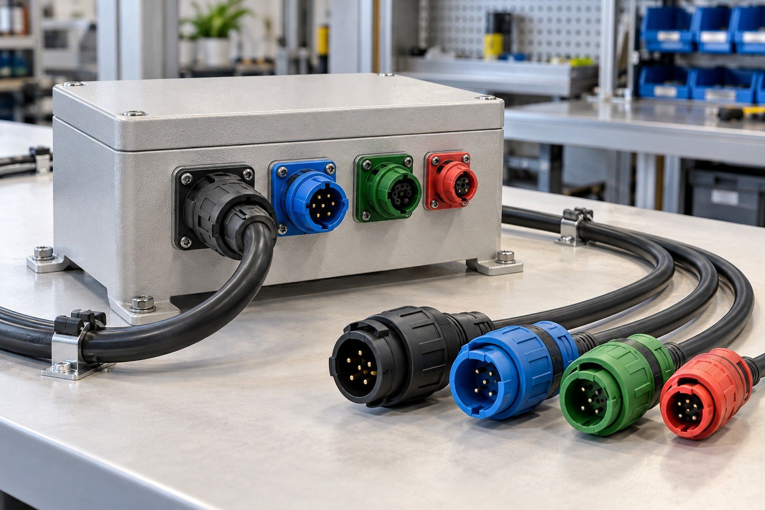
Match connector identity, keying and pin assignment to controlled wiring documents. Similar connector bodies do not prove the same electrical interface.
| Your input | Wiring diagram, pin schedule and approved connector models. |
|---|---|
| Your decision | Define connection checks and substitution approval. |
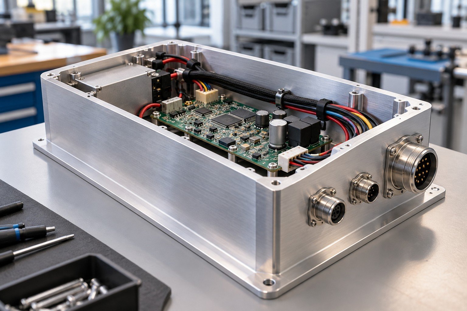
Electrical mechanical integration needs mechanical access and the clearances required by the approved product design. Review the complete enclosure and service condition.
| Your input | CAD, mounting details and required electrical clearances. |
|---|---|
| Your decision | Confirm fit, protection and access with the design owner. |
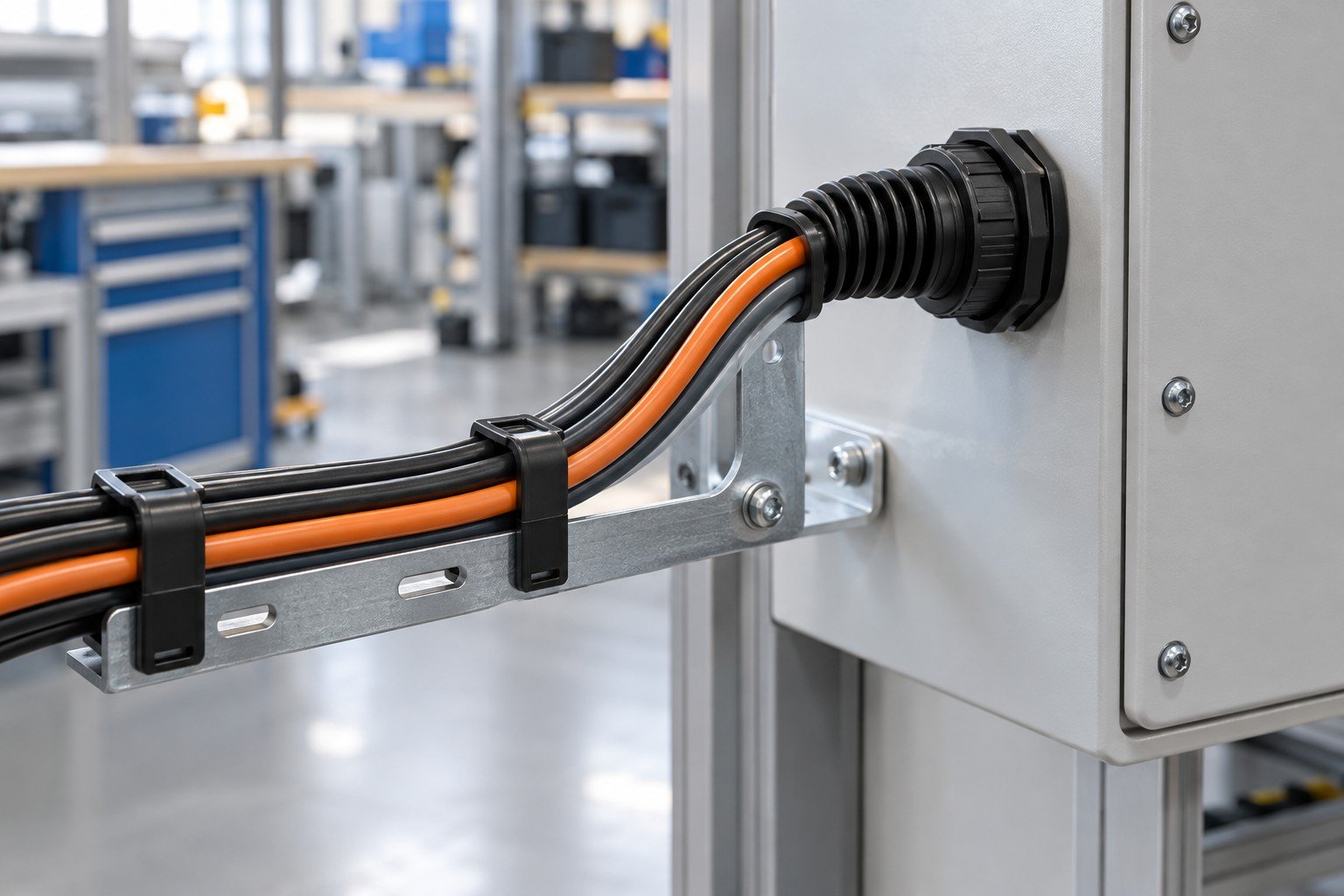
Define cable entry, bend requirements, edge protection, clips and strain relief. Use the approved cable and connector instructions.
| Your input | Harness drawing, supplier limits and installation route. |
|---|---|
| Your decision | Agree support points and inspection before closure. |
Electromechanical assembly for robotics and actuator modules needs defined cable movement as well as mechanical travel. Review interference in the intended operating envelope.
| Your input | Motion, travel, surrounding geometry and cable constraints. |
|---|---|
| Your decision | Agree routing and project-specific movement checks. |
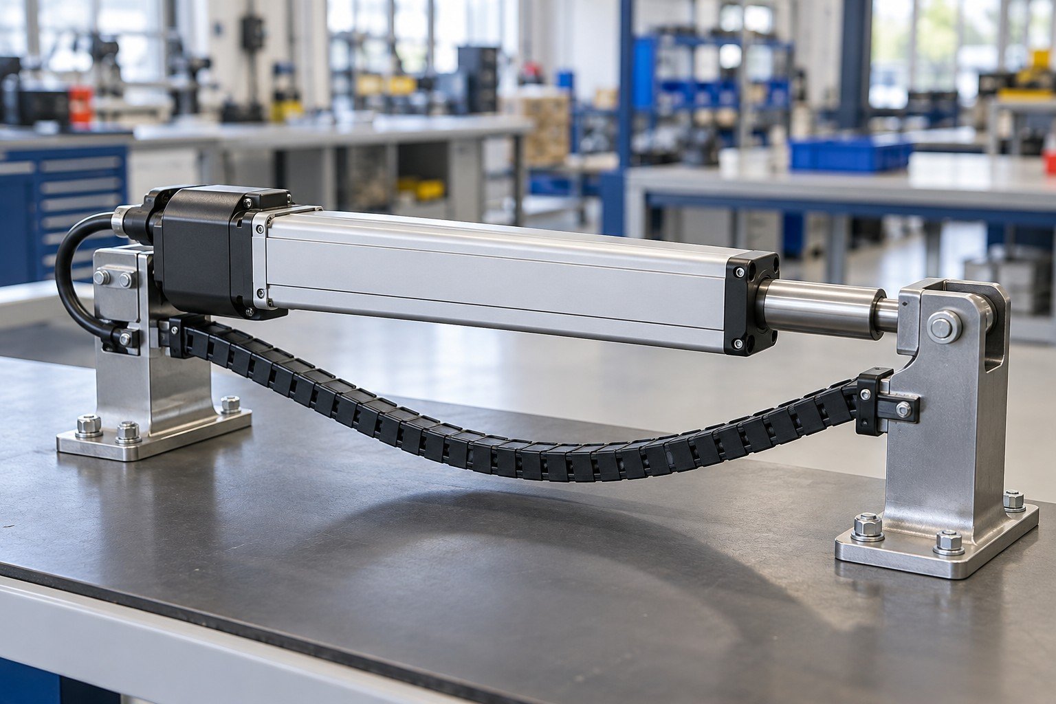
Grounding, bonding, insulation and applicable ESD controls follow your product requirements and approved process. Their presence alone does not establish regulatory compliance.
| Your input | Protection design, workmanship requirements and check method. |
|---|---|
| Your decision | Confirm required operations, resources and evidence. |
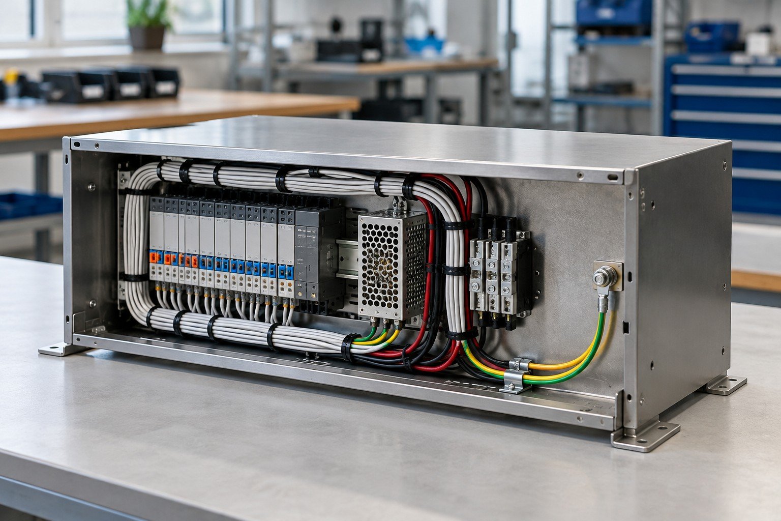
Mounting, cable bundles and covers can alter a thermal path. Review the final arrangement against your approved component and product requirements.
| Your input | Layout, ventilation and thermal interface specification. |
|---|---|
| Your decision | Define contact, routing and any required thermal validation. |
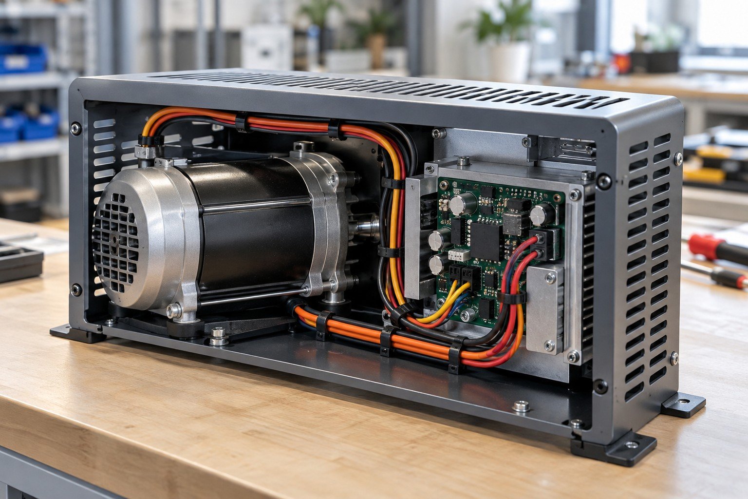
Electromechanical assembly quality control includes the approved mechanical, wiring and applicable firmware or settings baseline. Changes require review before use.
| Your input | BOM, drawings, wiring revision and configuration identifier. |
|---|---|
| Your decision | Control substitutions, software permissions and change records. |
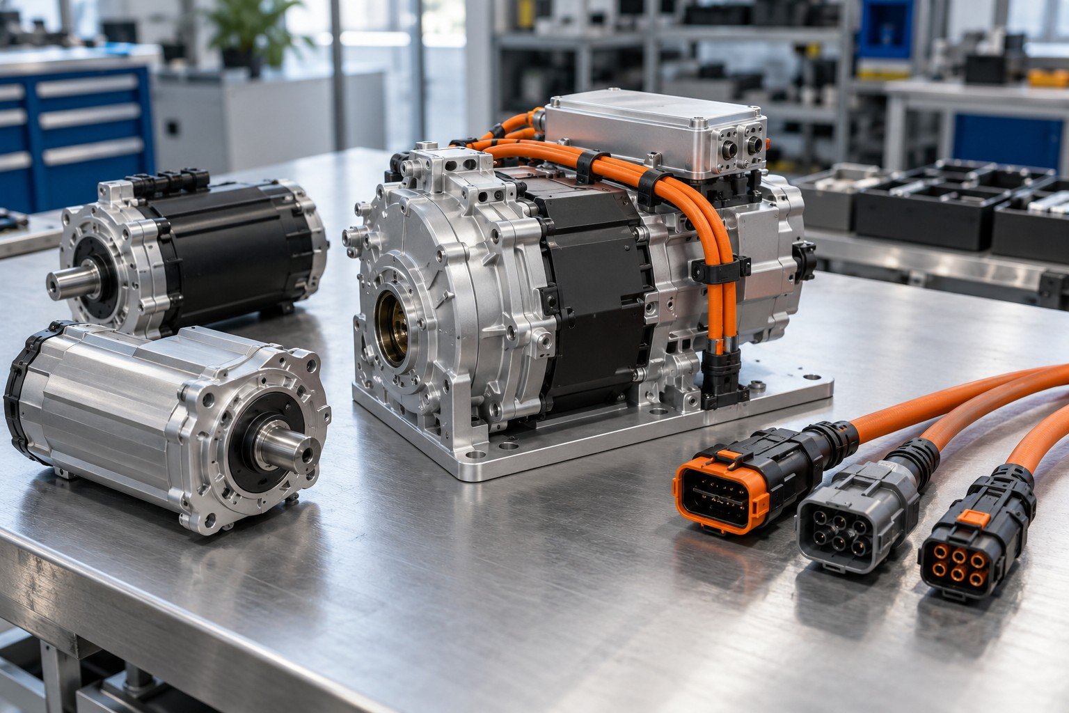
Electromechanical assembly and testing require a check plan. Connection, functional and product safety evidence answer different questions.
| Your input | Requirements, methods, coverage and pass/fail criteria. |
|---|---|
| Your decision | Confirm equipment, test development and qualification responsibility. |
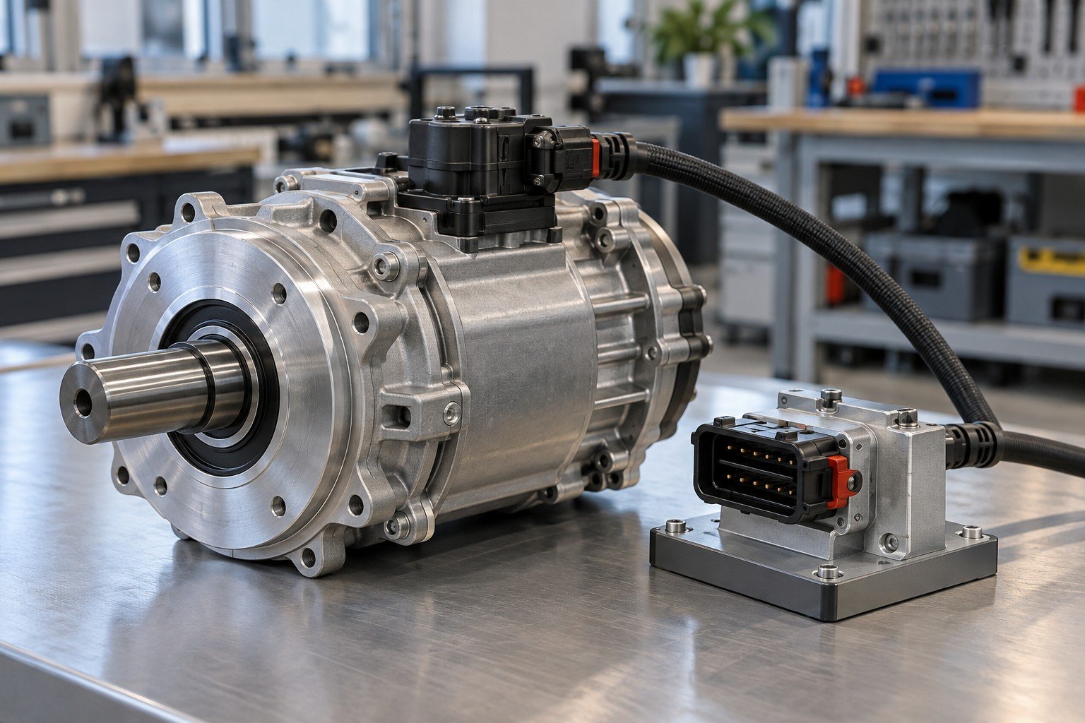
Connection checks, functional testing and required electrical safety evaluation have separate methods and acceptance responsibilities.
| 01 · Components | Approved models, part numbers and incoming condition. |
|---|---|
| 02 · Installation | Mounting, fasteners, routing and protected interfaces. |
| 03 · Connections | Defined pin map, seating and agreed electrical paths. |
| 04 · Configuration | Applicable firmware, settings and procedure revision. |
| 05 · Function | Specified operating conditions, limits and check results. |
| 06 · Release | Identity, deviations, approval and delivered records. |
Confirm applicable electrical safety testing, equipment and product qualification separately. A continuity result or successful power-on does not establish certification.
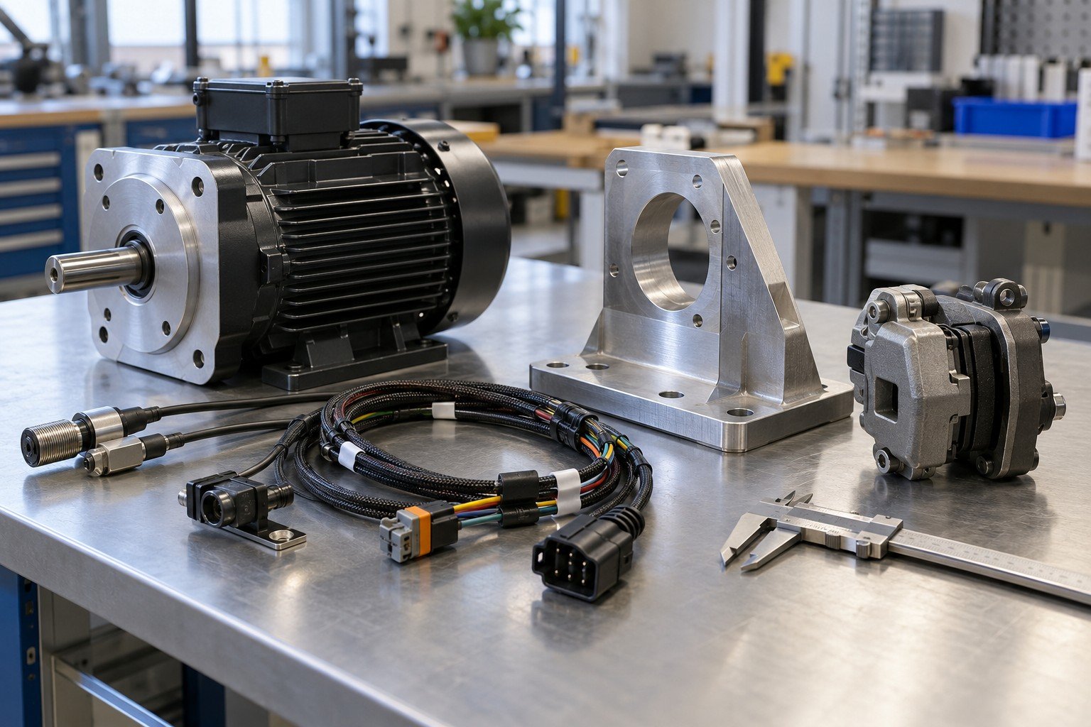
| 01 · Components | Approved models, part numbers and incoming condition. |
|---|---|
| 02 · Installation | Mounting, fasteners, routing and protected interfaces. |
| 03 · Connections | Defined pin map, seating and agreed electrical paths. |
| 04 · Configuration | Applicable firmware, settings and procedure revision. |
| 05 · Function | Specified operating conditions, limits and check results. |
| 06 · Release | Identity, deviations, approval and delivered records. |
Confirm applicable electrical safety testing, equipment and product qualification separately. A continuity result or successful power-on does not establish certification.
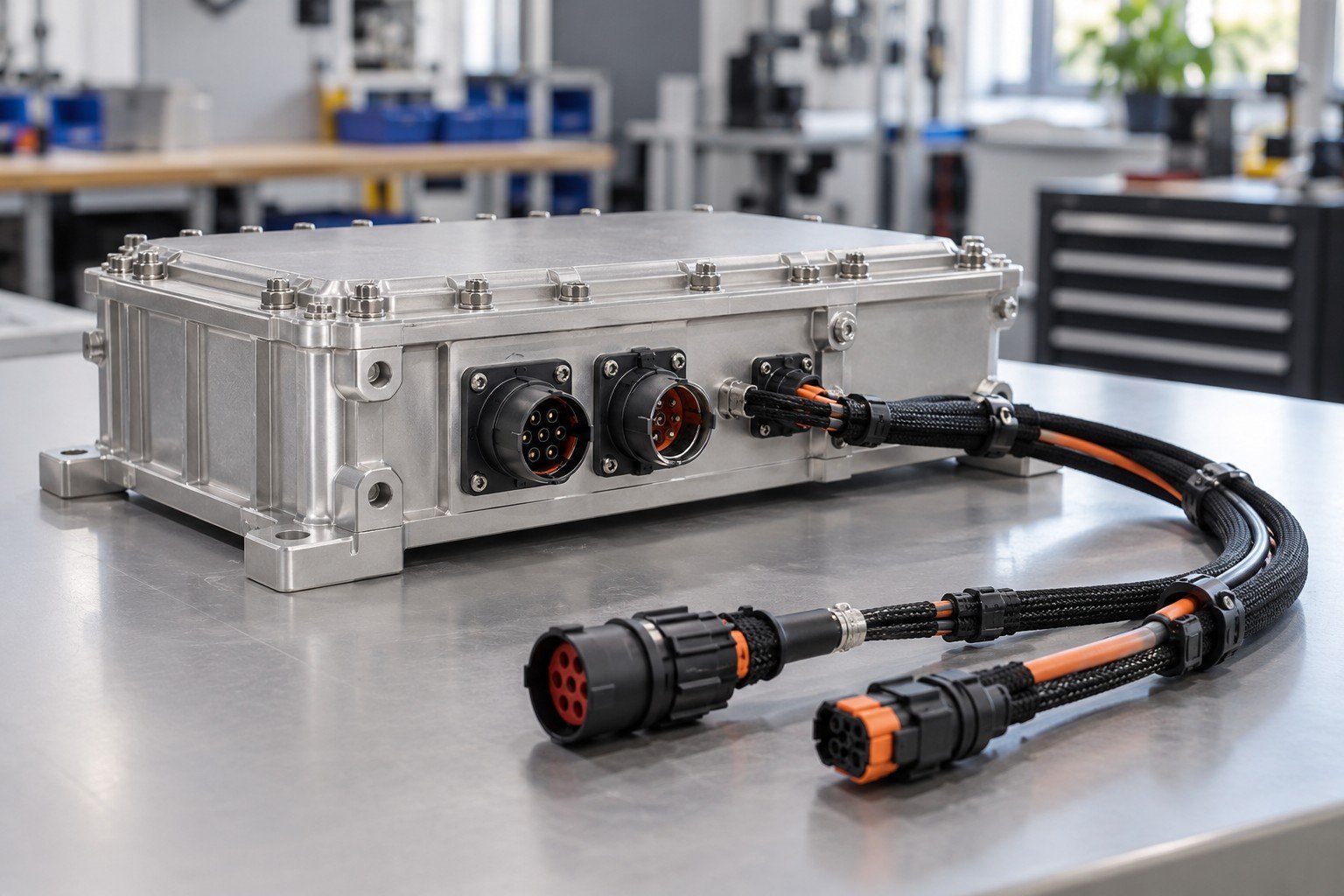
| 01 · Components | Approved models, part numbers and incoming condition. |
|---|---|
| 02 · Installation | Mounting, fasteners, routing and protected interfaces. |
| 03 · Connections | Defined pin map, seating and agreed electrical paths. |
| 04 · Configuration | Applicable firmware, settings and procedure revision. |
| 05 · Function | Specified operating conditions, limits and check results. |
| 06 · Release | Identity, deviations, approval and delivered records. |
Confirm applicable electrical safety testing, equipment and product qualification separately. A continuity result or successful power-on does not establish certification.
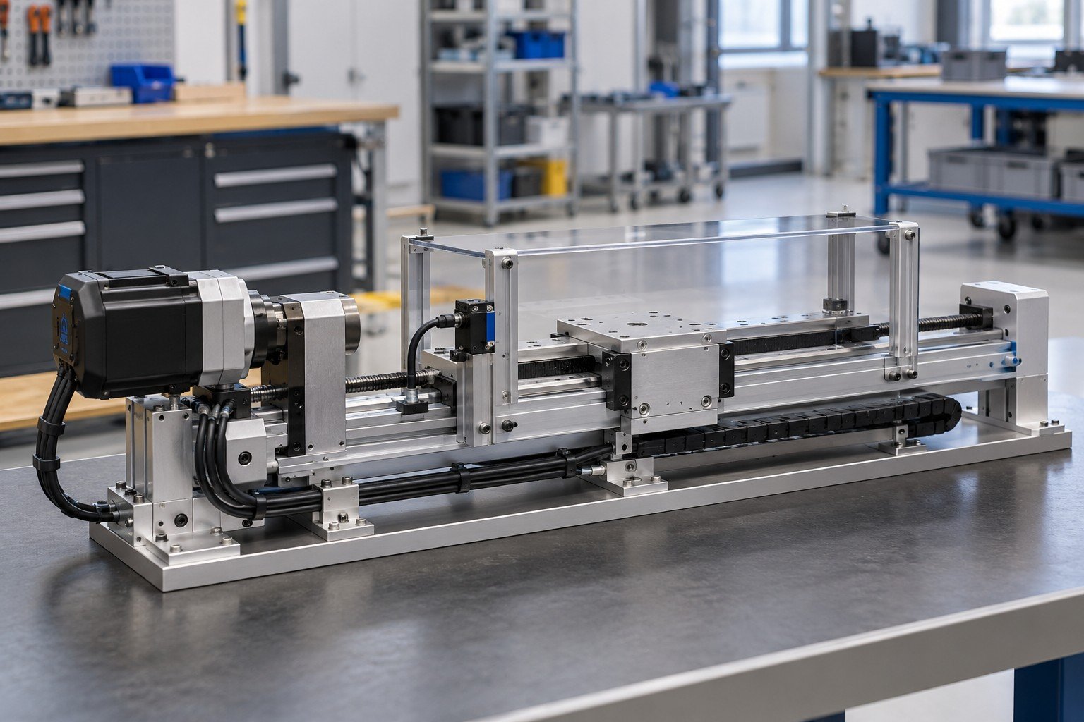
| 01 · Components | Approved models, part numbers and incoming condition. |
|---|---|
| 02 · Installation | Mounting, fasteners, routing and protected interfaces. |
| 03 · Connections | Defined pin map, seating and agreed electrical paths. |
| 04 · Configuration | Applicable firmware, settings and procedure revision. |
| 05 · Function | Specified operating conditions, limits and check results. |
| 06 · Release | Identity, deviations, approval and delivered records. |
Confirm applicable electrical safety testing, equipment and product qualification separately. A continuity result or successful power-on does not establish certification.
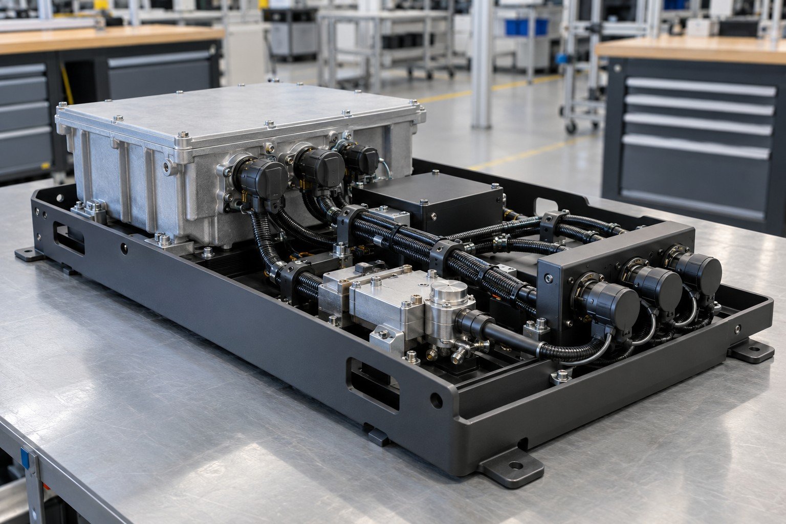
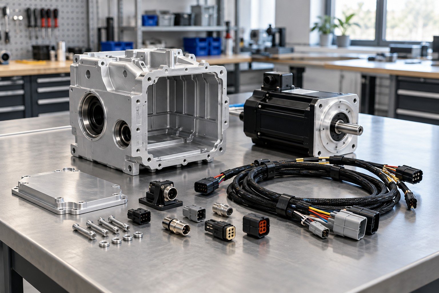
Record what enters the build, what is assembled and what your team will integrate afterward.
Keep the build, configuration and check records on the same approved revision.
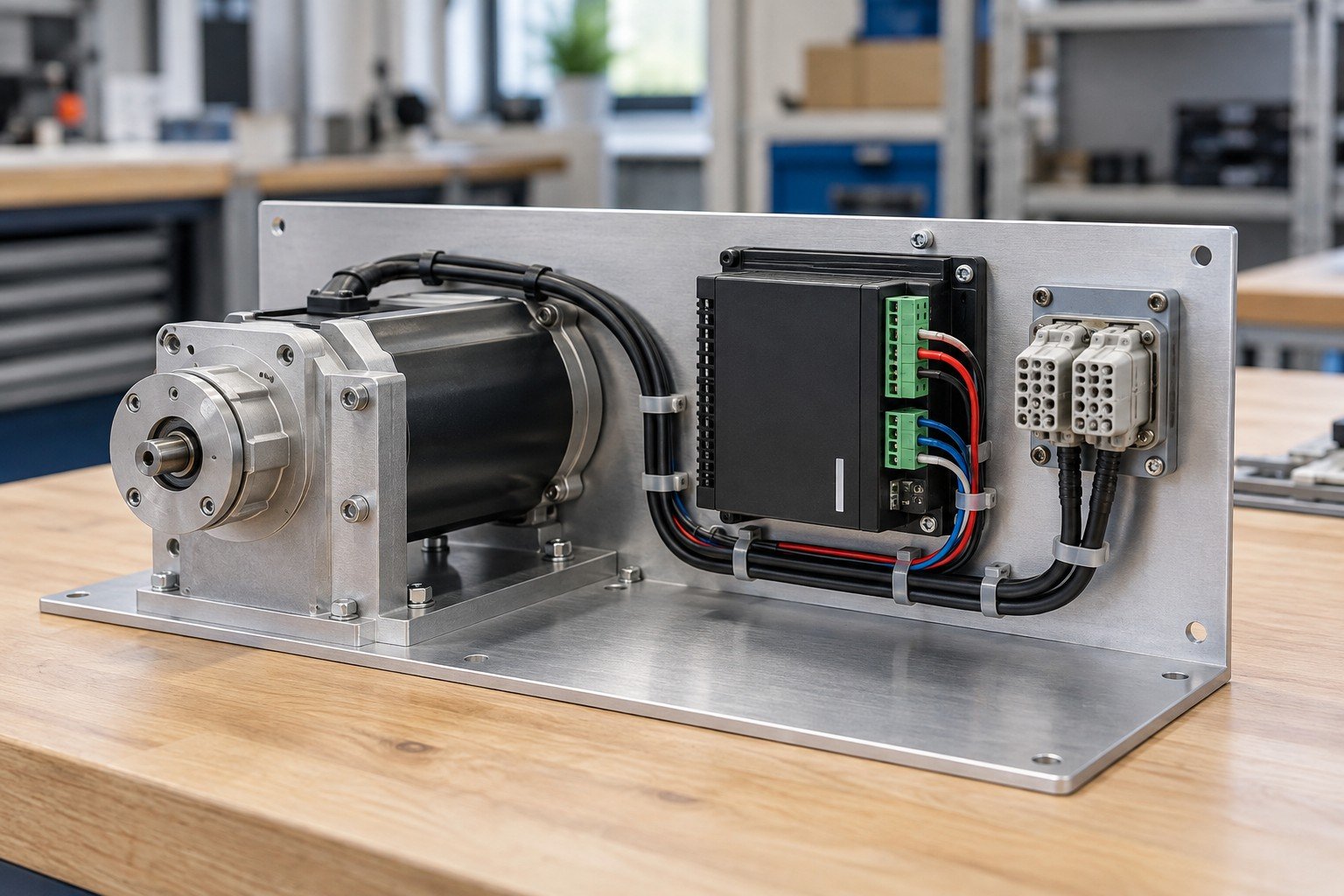
Align BOM, approved sources, supplied items and substitution approval.
Keep the build, configuration and check records on the same approved revision.
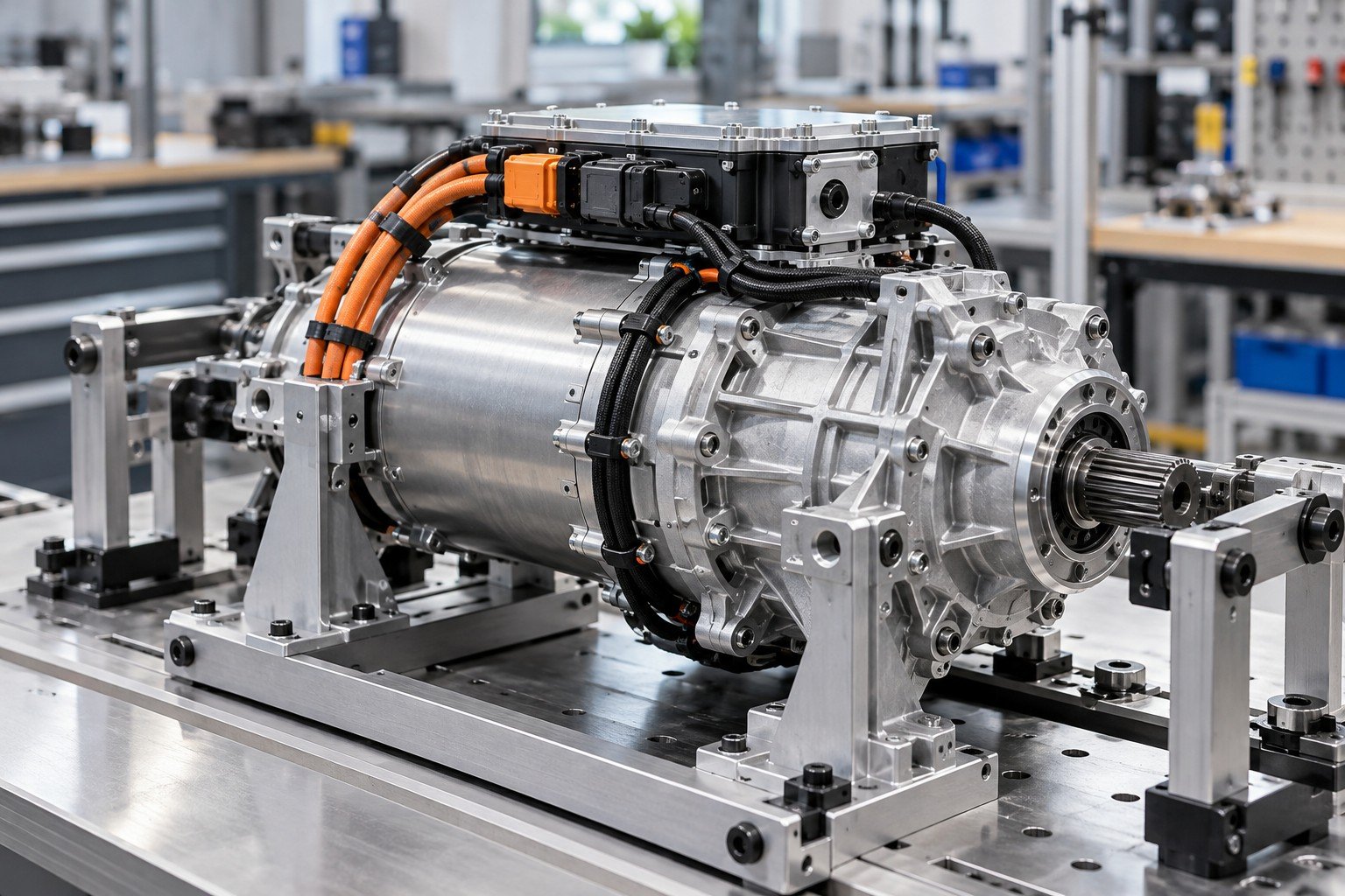
Resolve access, locating features, cable routes and applicable configuration before the first build.
Keep the build, configuration and check records on the same approved revision.
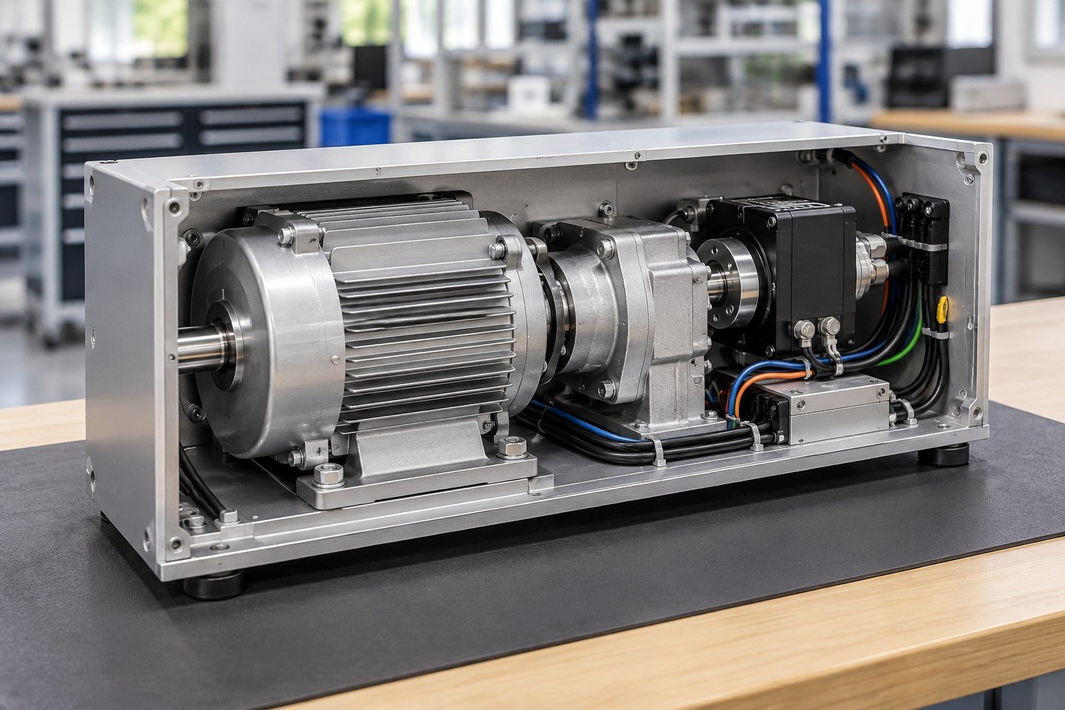
Check interfaces and connection access on the actual assembly, including the steps hidden by later closure.
Keep the build, configuration and check records on the same approved revision.
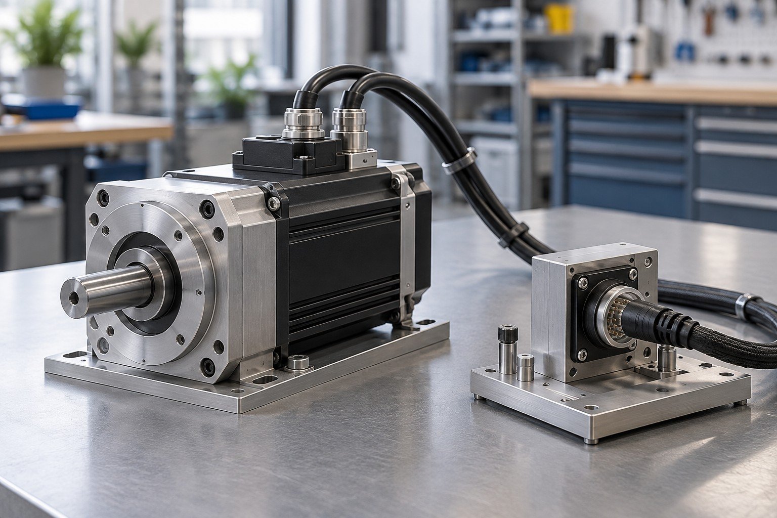
Identify method, equipment, coverage, limits and record format. Confirm specialized tests separately.
Keep the build, configuration and check records on the same approved revision.
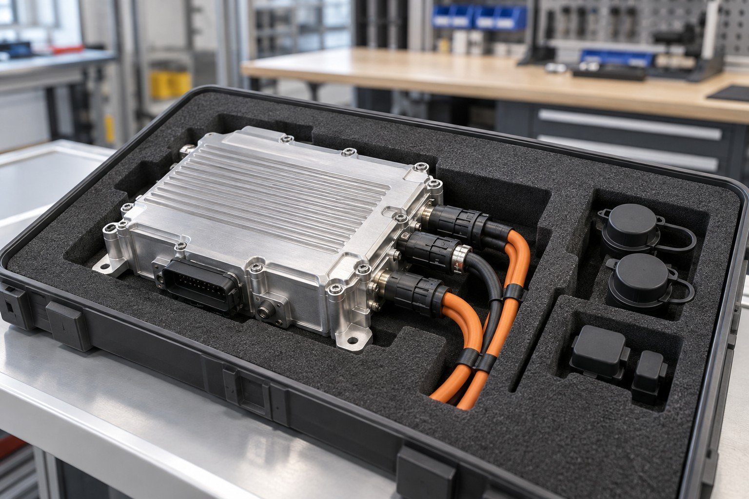
Deliver the agreed identity, configuration, check results and protected receiving condition.
Keep the build, configuration and check records on the same approved revision.
Your electromechanical assembly manufacturer should identify what is manufactured, purchased, installed and checked in the quoted scope.
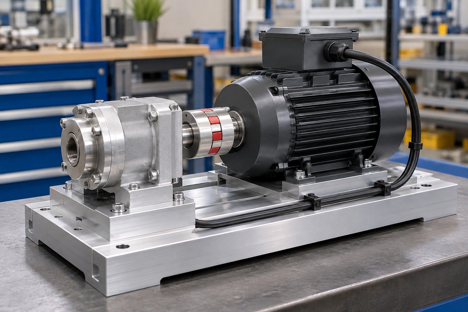
Identify mounting datums, fasteners, finish and access for the electrical items.
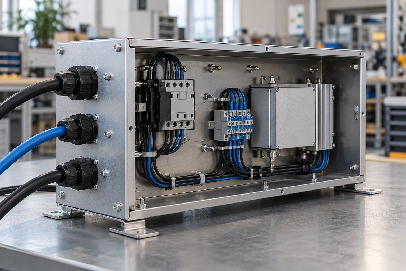
Define component layout, cable entry, protected surfaces and closure sequence.
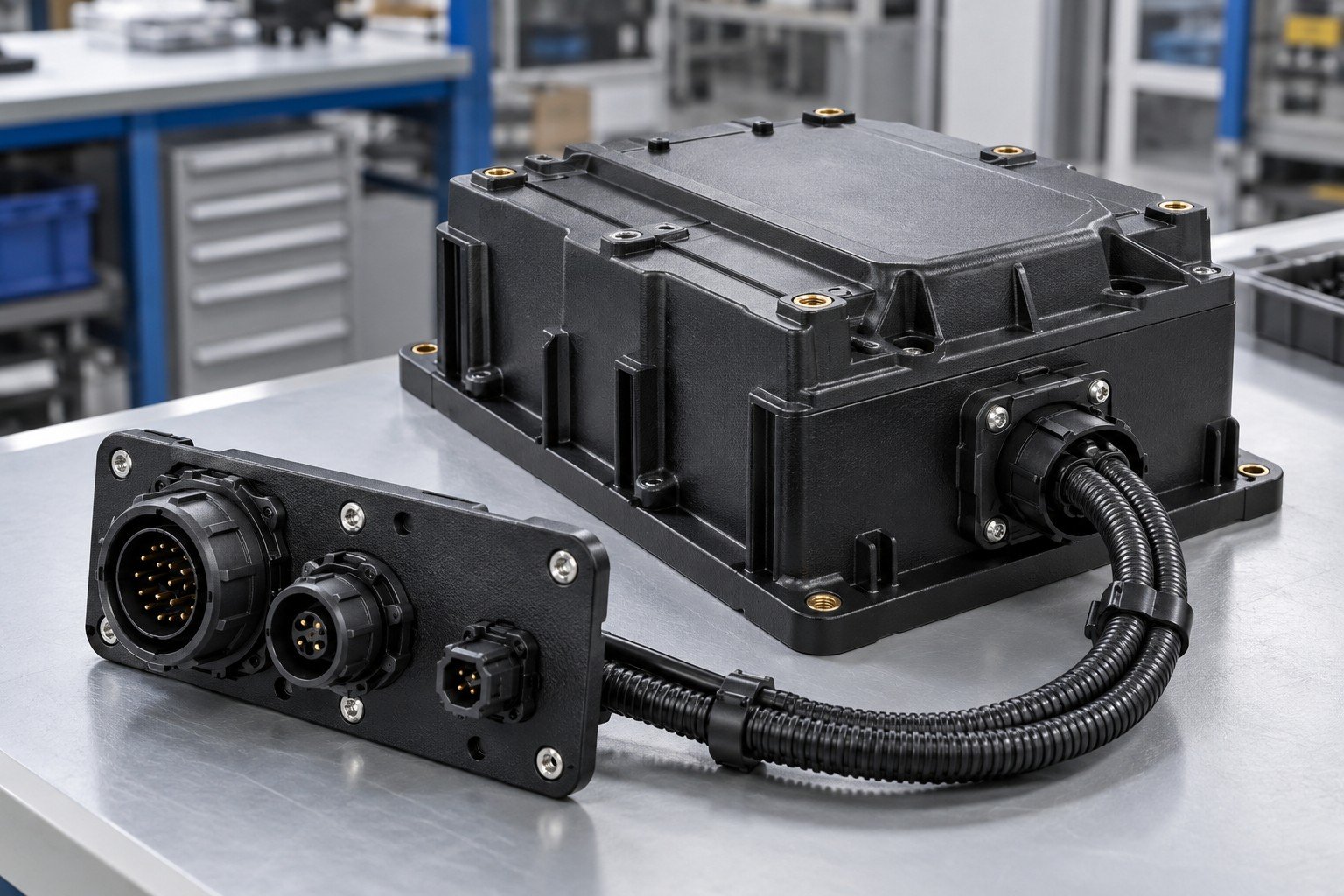
Confirm inserts, mounting loads, material condition and interface requirements.
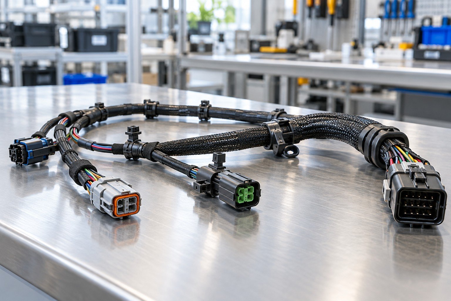
Provide part numbers, pin maps, connector keying and installation requirements.
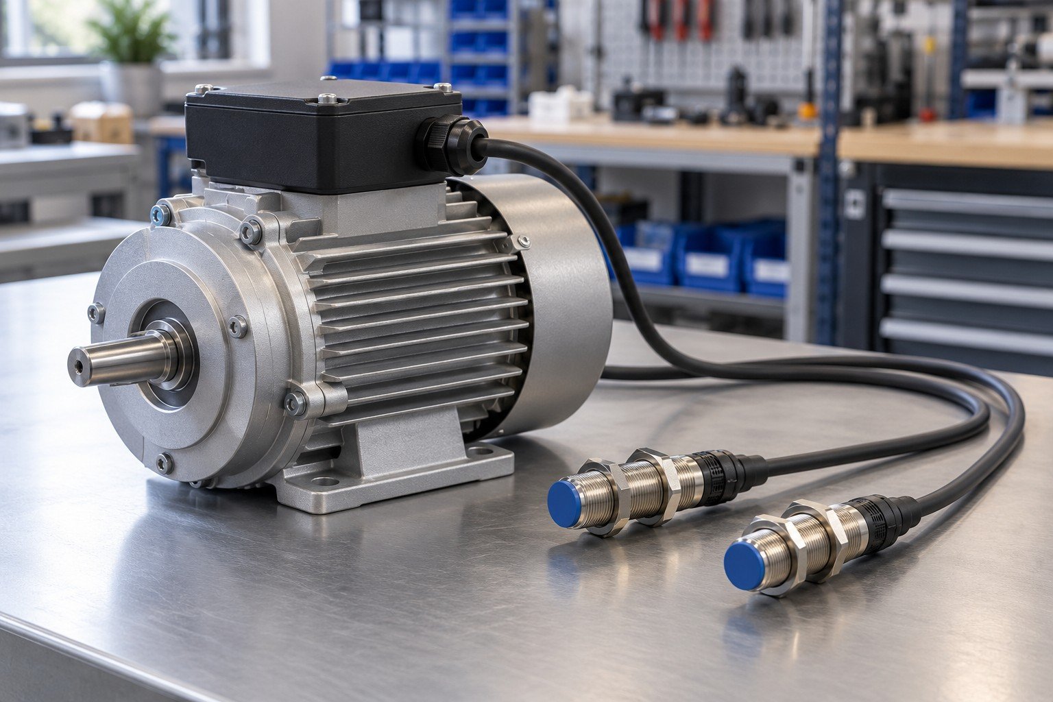
Use approved models and datasheets; define mounting, wiring and check scope.
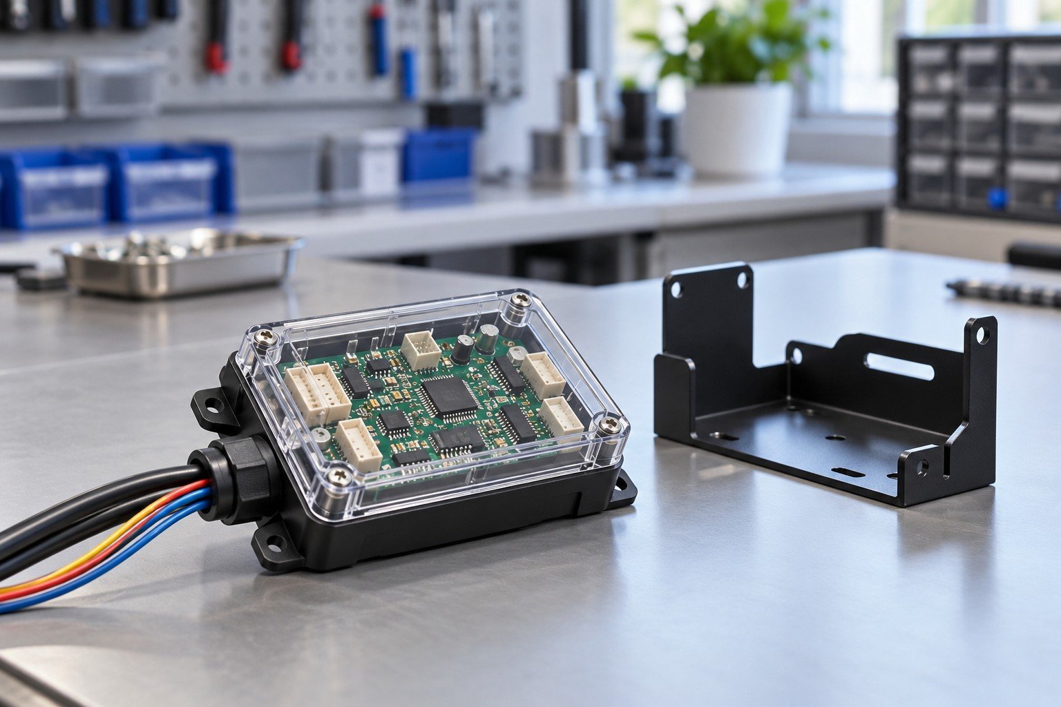
Identify incoming PCBA or module responsibility and required handling; in-house board fabrication is not implied.
For electromechanical contract manufacturing, separate components, nonrecurring work, repeat assembly and verification.
Consigned components, approved sourcing or a defined combination.
Fixtures, setup, work instructions and agreed test development.
Assembly, applicable configuration, checks, records and packing.
RELEASE-PLANNING EXAMPLE — NOT A PRICE OR CUSTOMER CASE
3 linked records for this illustrative scope. Define the actual records, unit or lot identity and retention in your quotation; this is not a certification claim.
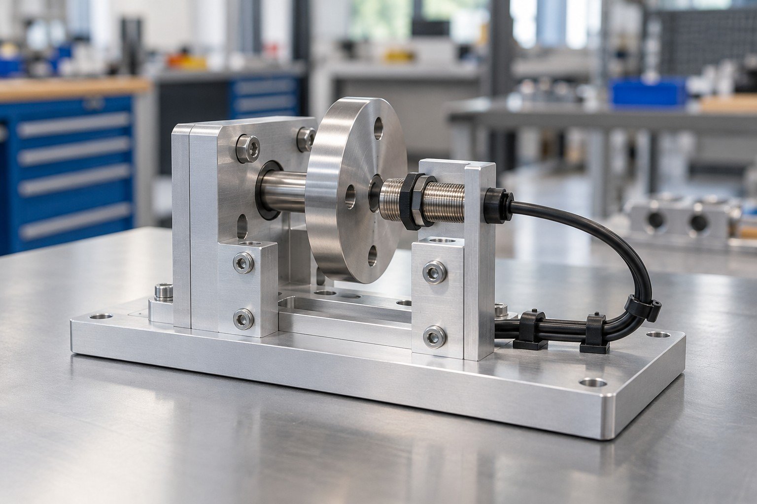
Industrial electromechanical assembly reviewed around your equipment interfaces and accepted function.
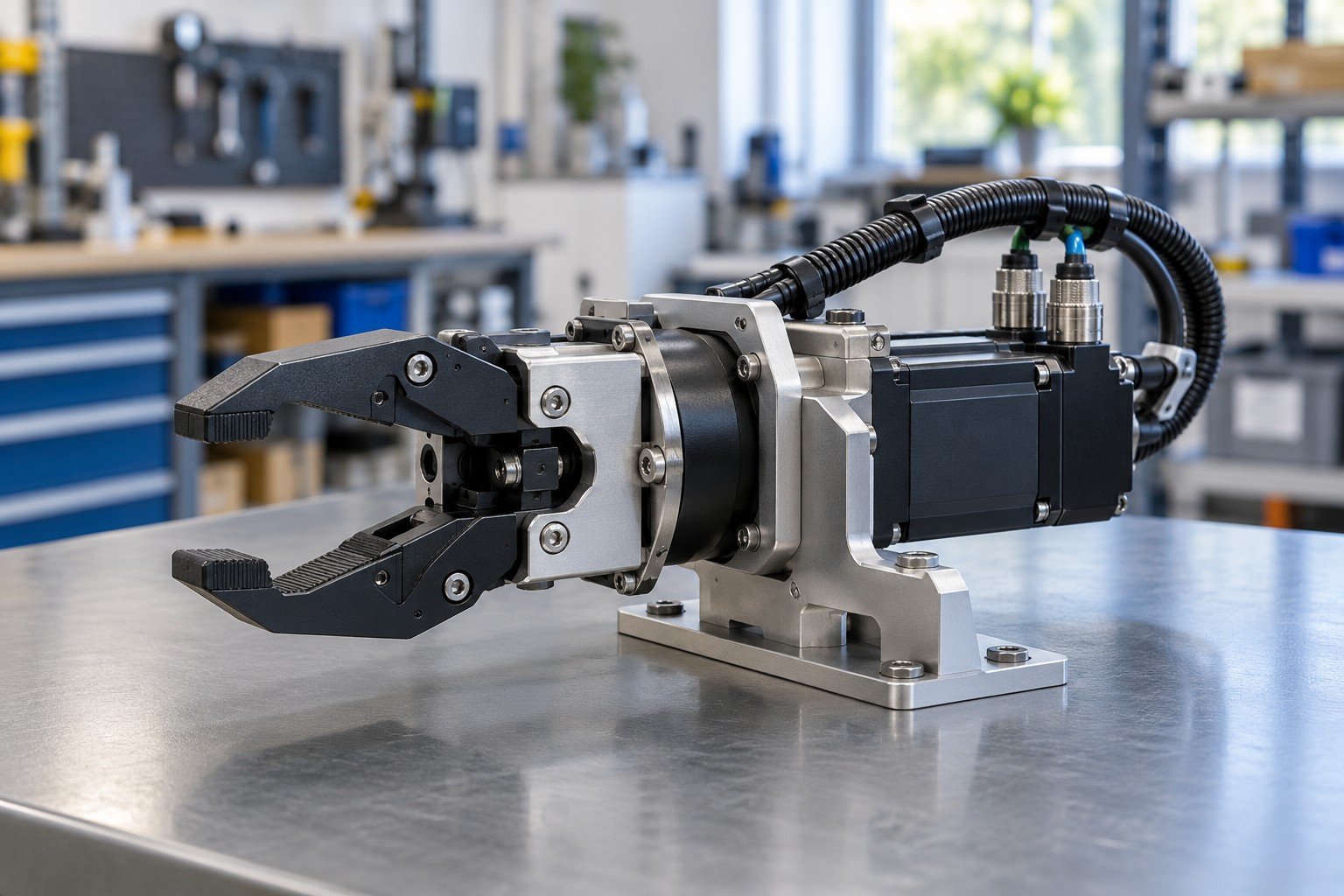
Coordinate actuator mounts, sensors, cable movement and the next integration boundary.
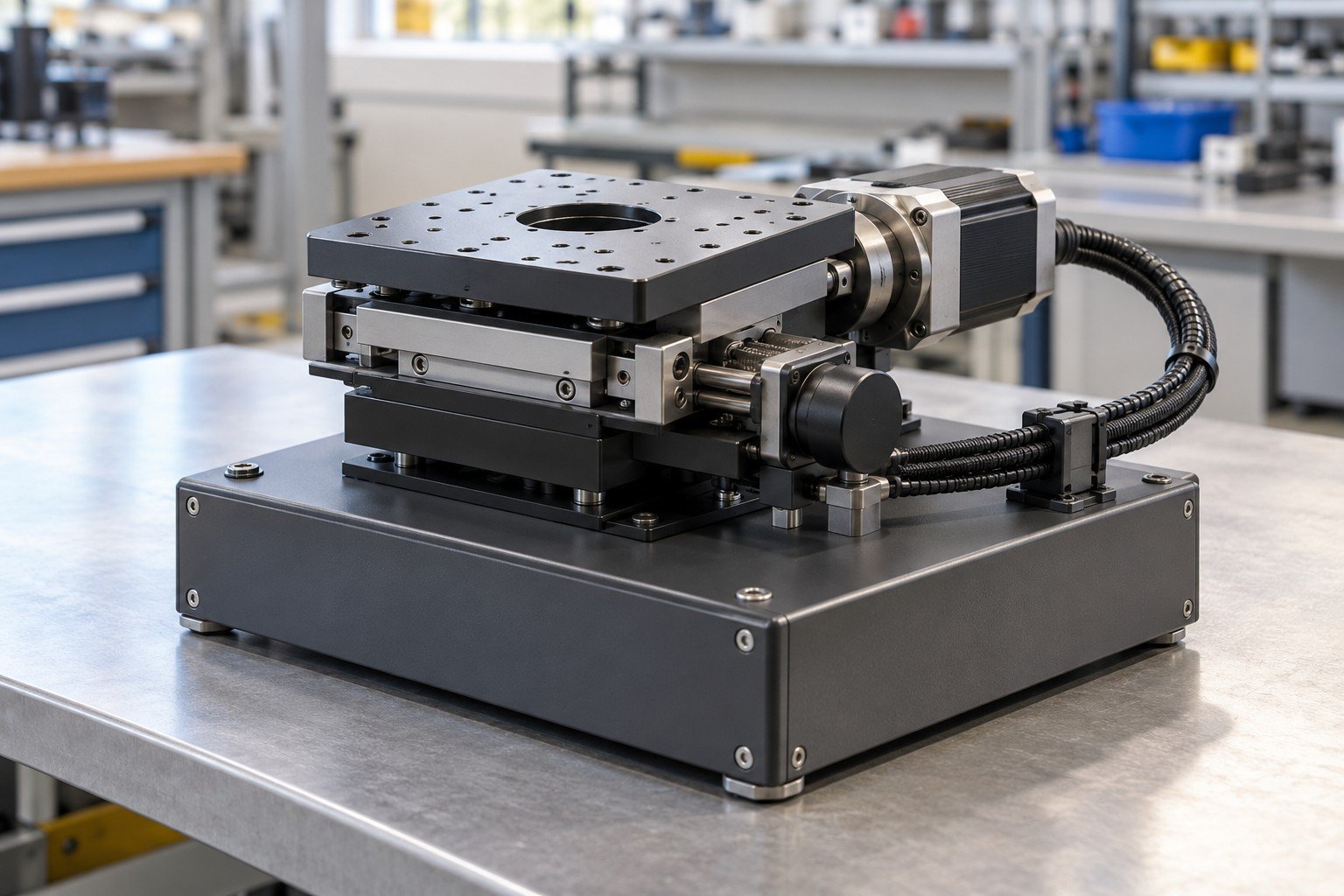
Define motion, sensing, settings and the conditions for your required checks.
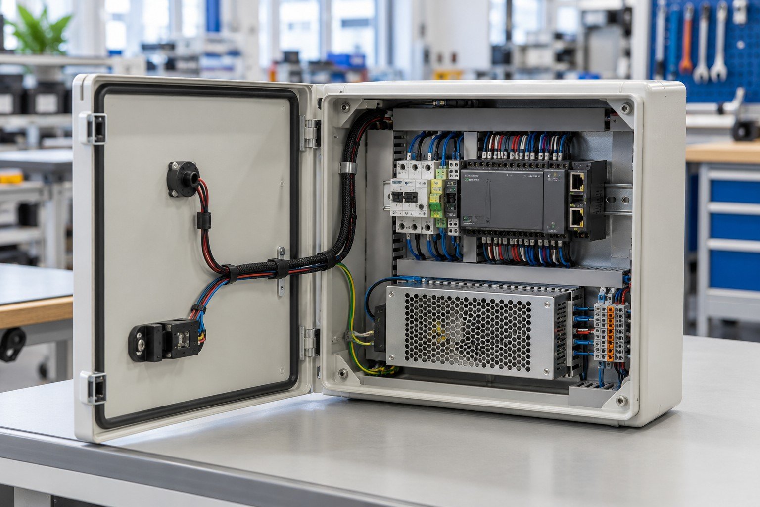
Box build manufacturing reviewed around your enclosure, approved components and delivered scope.
Illustrative product concepts, not actual customer case studies. Scope, suitability and qualification are project-specific.
Coordinate your document review, component supply, first-build decisions and delivery with the responsible project team.

Resolve build questions and record approved decisions.
Identify component ownership and permitted substitutions.
Confirm check resources, records and release authority.
Agree configuration identity, protection and receiving needs.
Request an NDA before sharing confidential files. Missing documents can enter a scope review; define required engineering or test development separately.
Controlled BOM, drawings, wiring and applicable configuration.
Installed condition, connections and agreed functional evidence.
Unit or lot identity, records, protection and receiving requirements.
Approve changes before the next release, including purchased-item substitutions and configuration updates.
Electromechanical assembly combines mechanical structures and electrical components into a defined functional module or system. An approved motor, mounting bracket, connector and sensor can form an electromechanical subassembly. The quotation should identify the actual installation, wiring and check scope.
Electromechanical assembly describes integrating mechanical and electrical parts. Box build assembly usually centers on an enclosure and its installed components, connections and delivered system condition. Not every electromechanical module needs a box or a circuit board; define your actual product boundary.
Box build assembly brings an enclosure, mounting components, approved electrical items and required connections into an agreed delivered unit. It can include purchased PCBAs or harnesses without implying that every component is manufactured by the assembler.
No. PCB assembly populates and connects components on a circuit board. Electromechanical system assembly concerns the broader module, which may integrate a purchased board, housing, motor, harness or sensor. Board fabrication and assembly require their own confirmed supply scope.
Cost depends on components, sourcing, fixtures, work instructions, assembly, applicable configuration, test development, checks and packaging. Compare quotes on the same BOM, quantities and acceptance requirements; separate nonrecurring work from repeat unit work.
Provide the BOM and approved sources, assembly drawings, wiring and interface documents, quantities, supply ownership, function and test requirements. Include applicable firmware or settings, identification, packaging and delivery needs. Missing data should become a named review task, not an undocumented assumption.
Component supply is reviewed against approved part numbers, sources and availability. Identify customer-supplied items and agree purchasing responsibility, substitution approval, shortages, incoming defects and unused stock. Turnkey scope does not mean unrestricted substitution or all items held in stock.
Use agreed installation and connection checks plus functional tests under specified conditions. State coverage, limits, equipment and records. Electrical safety tests, load/endurance validation and product certification are distinct requirements whose resources and responsibilities must be confirmed.
Electromechanical assembly minimum order and electromechanical assembly lead time depend on component availability, fixtures, first-build approval, test development, quantity and scheduling. Send trial and repeat demand with the required date for a project-specific quotation.
Compare the same delivered scope: manufactured versus purchased items, supply ownership, document control, wiring, configuration, test resources and release evidence. For precision electromechanical assembly, ask how your stated fit and function will be checked rather than relying on a service label.