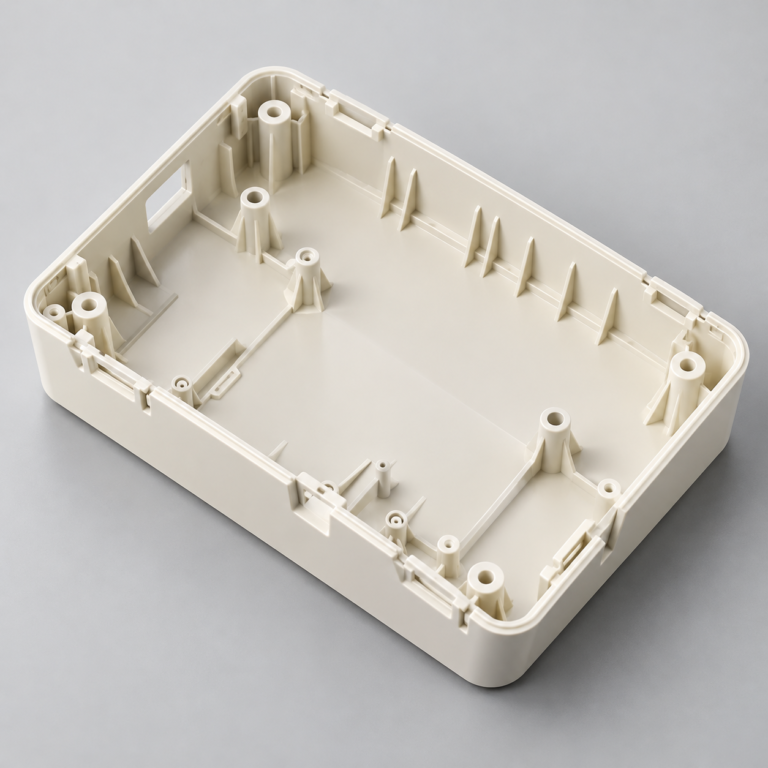
Injection Molding
Tooling and molding for your repeat plastic parts.
From prototype to production, coordinated manufacturing solutions for your custom parts.
View All Services →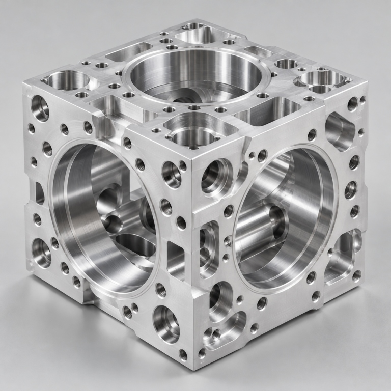
Precision parts for your tight tolerances and complex geometry.
Tooling and molding for your repeat plastic parts.
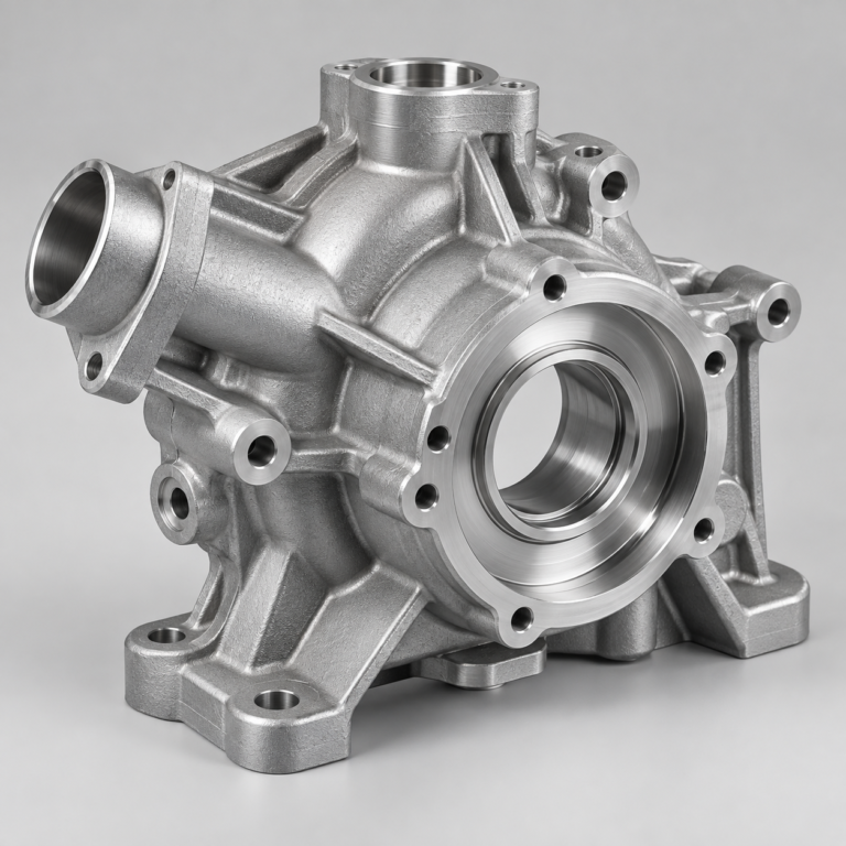
Metal casting options for your part and production volume.
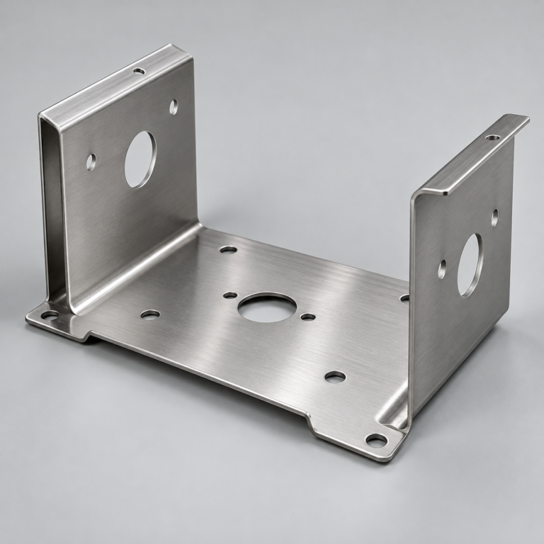
Cutting, forming and welding for your fabricated parts.
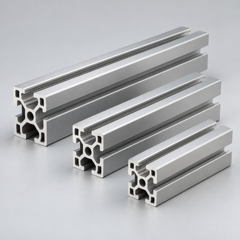
Custom profiles for your section, length and finish requirements.
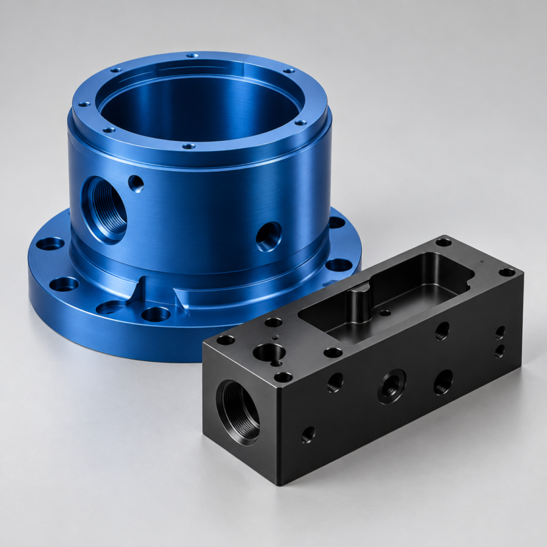
Finishes for your appearance, corrosion and wear requirements.
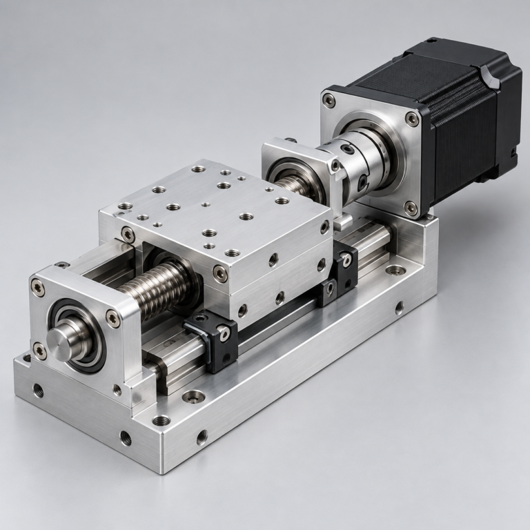
Sub-assemblies and final builds for your production program.
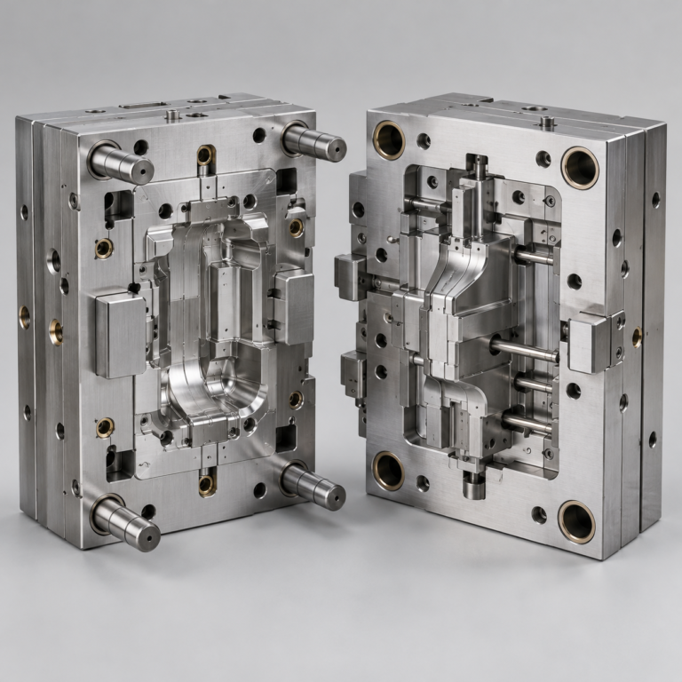
Production tooling built around your process and volume.
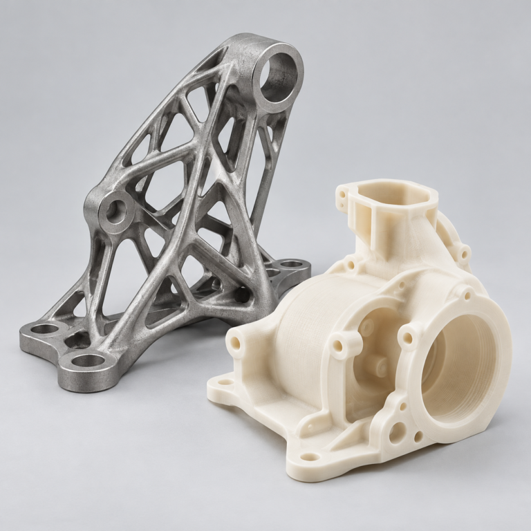
Prototype parts to check fit, function and design.
Choose air- or liquid-cooling components around your thermal and mechanical requirements.
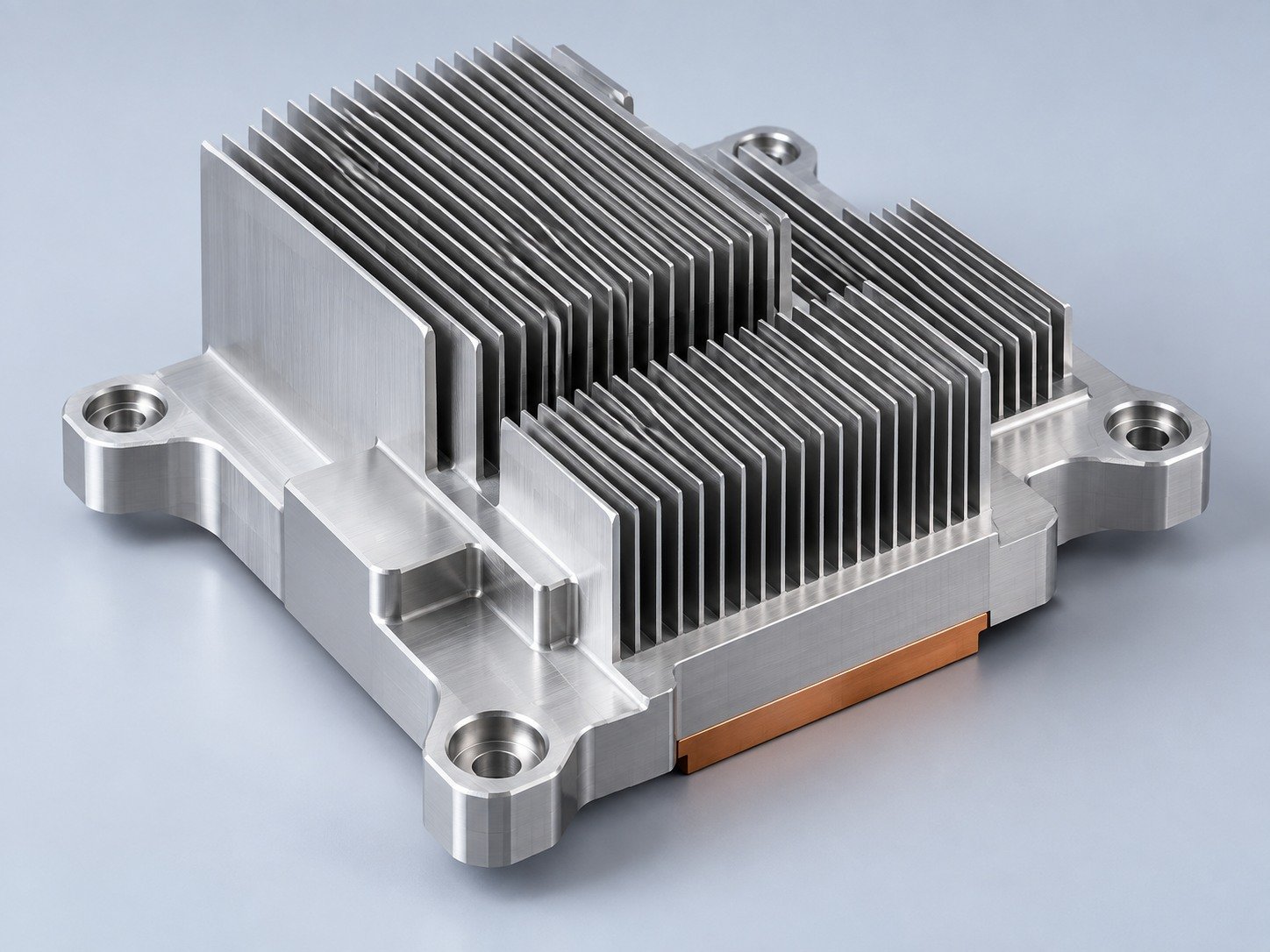
Manufacturing support for your cold plates, manifolds and cooling assemblies.
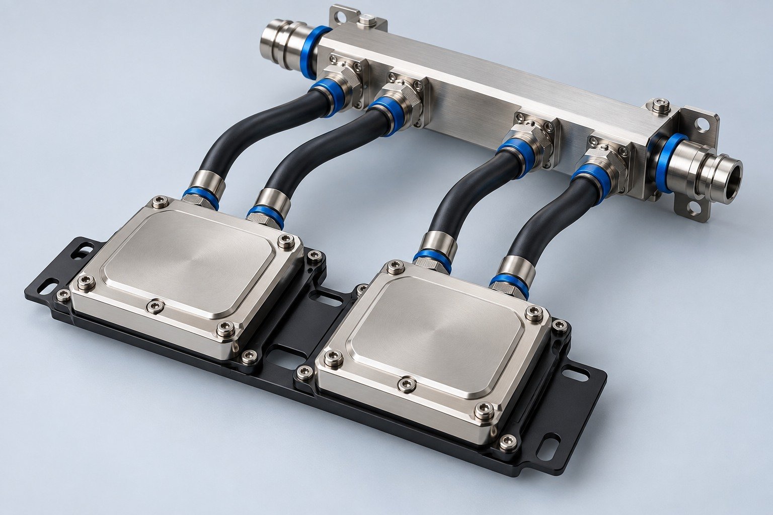
Find components for your power electronics, energy, laser and telecom application.
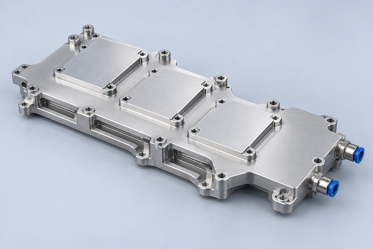
Components for your electronic systems.
Start with your functional and quality requirements.
Build around your operating environment.
From prototype to production, review material performance, manufacturability and cost for your part.
Review grade, temper and finish for your metal parts.
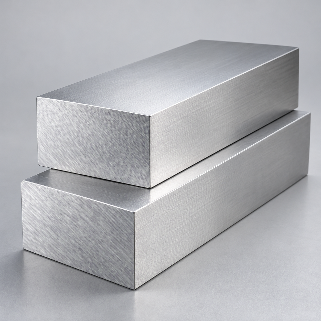 AluminumStrength, weight and machining›
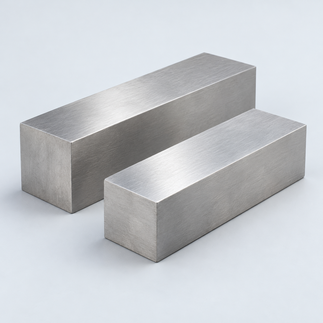 Stainless SteelCorrosion and finish requirements›
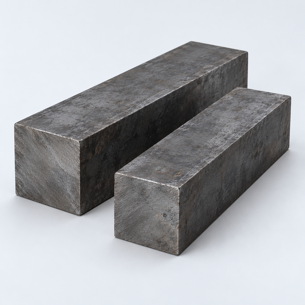 Carbon & Alloy SteelDiscuss grade and heat treatment›
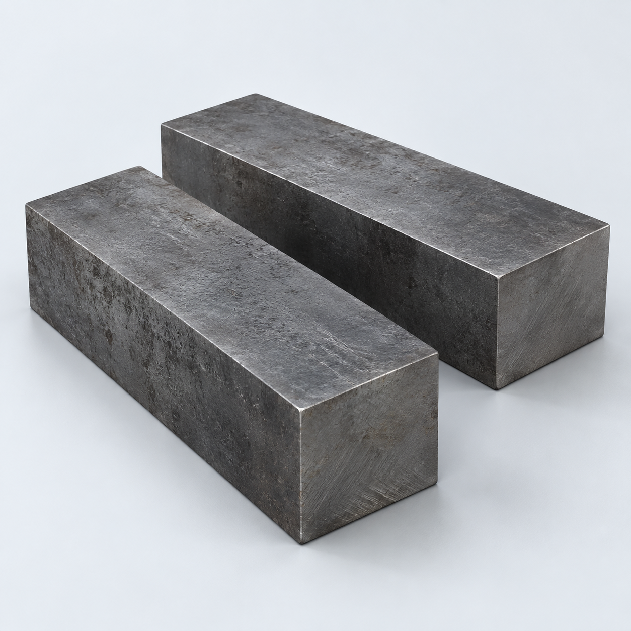 Tool SteelDiscuss tooling and wear needs›
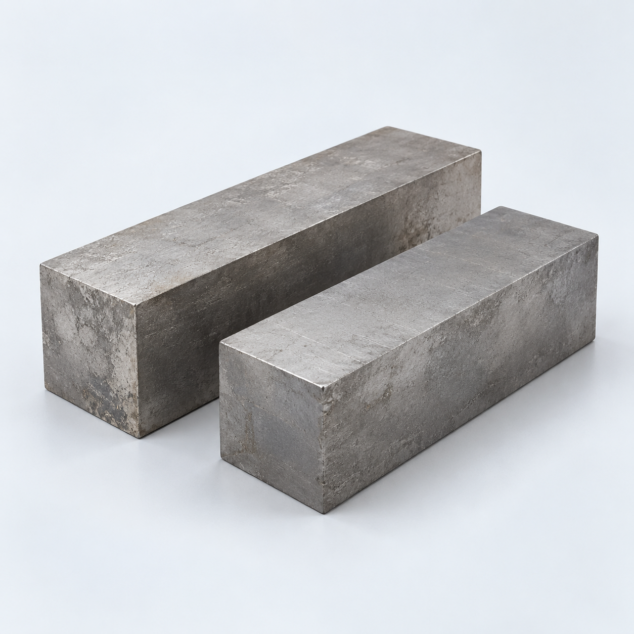 TitaniumReview grade and part geometry›
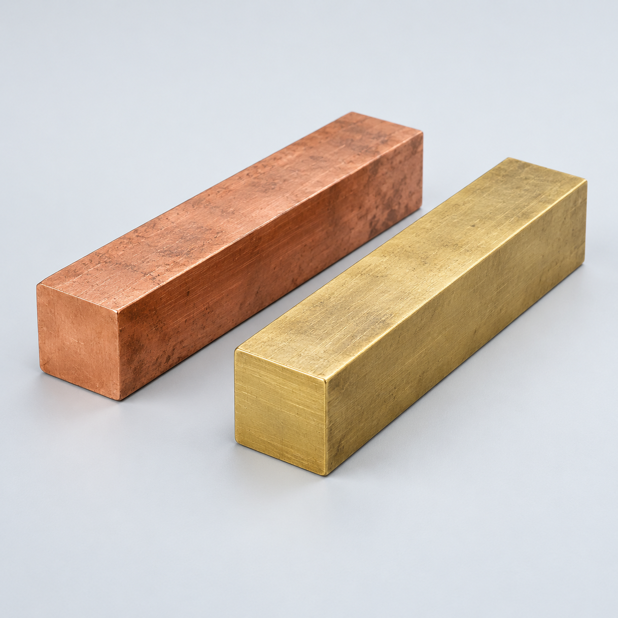 Copper & BrassDiscuss conductivity and machining›
Match your polymer to function, process and environment.
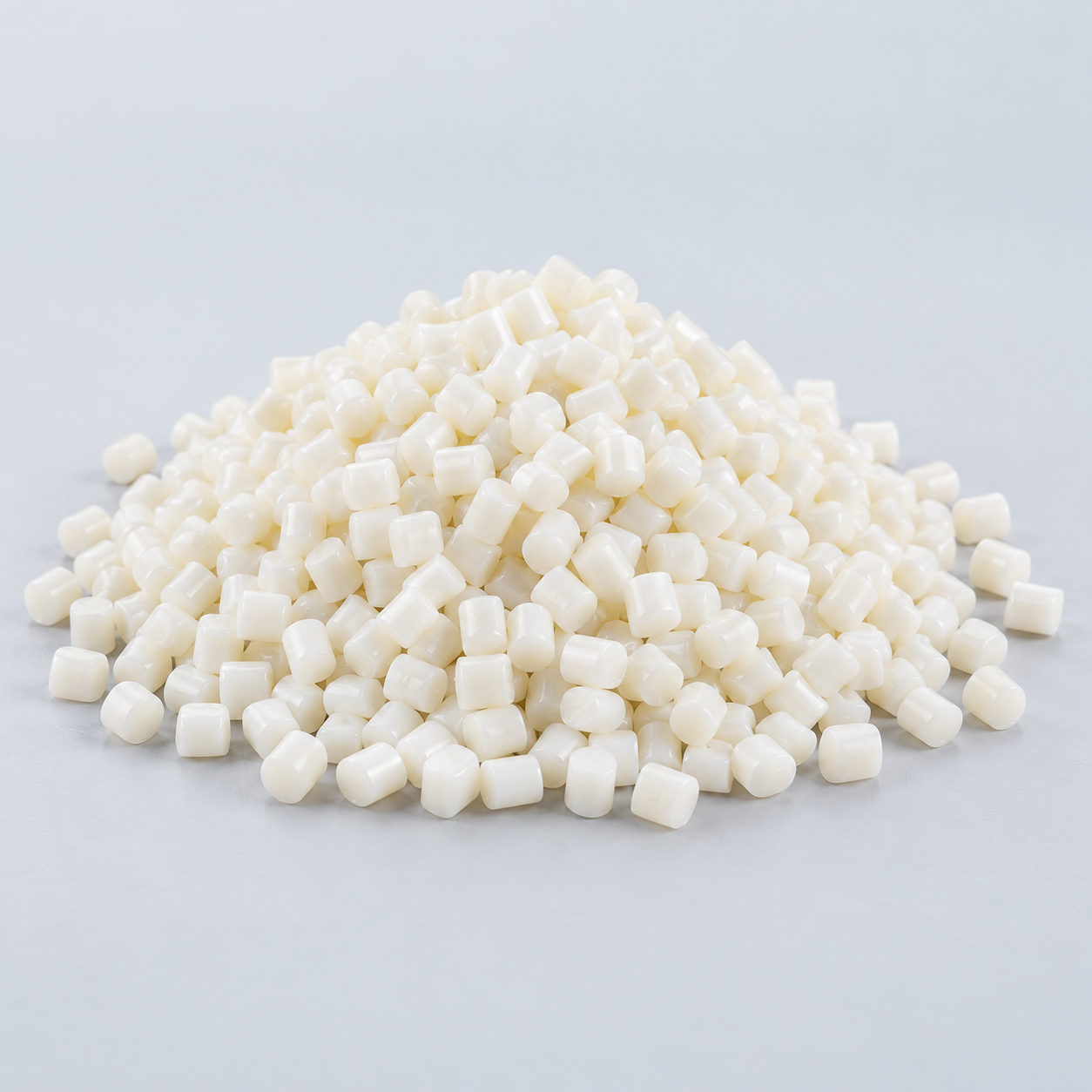 ABSReview enclosure and molding needs›
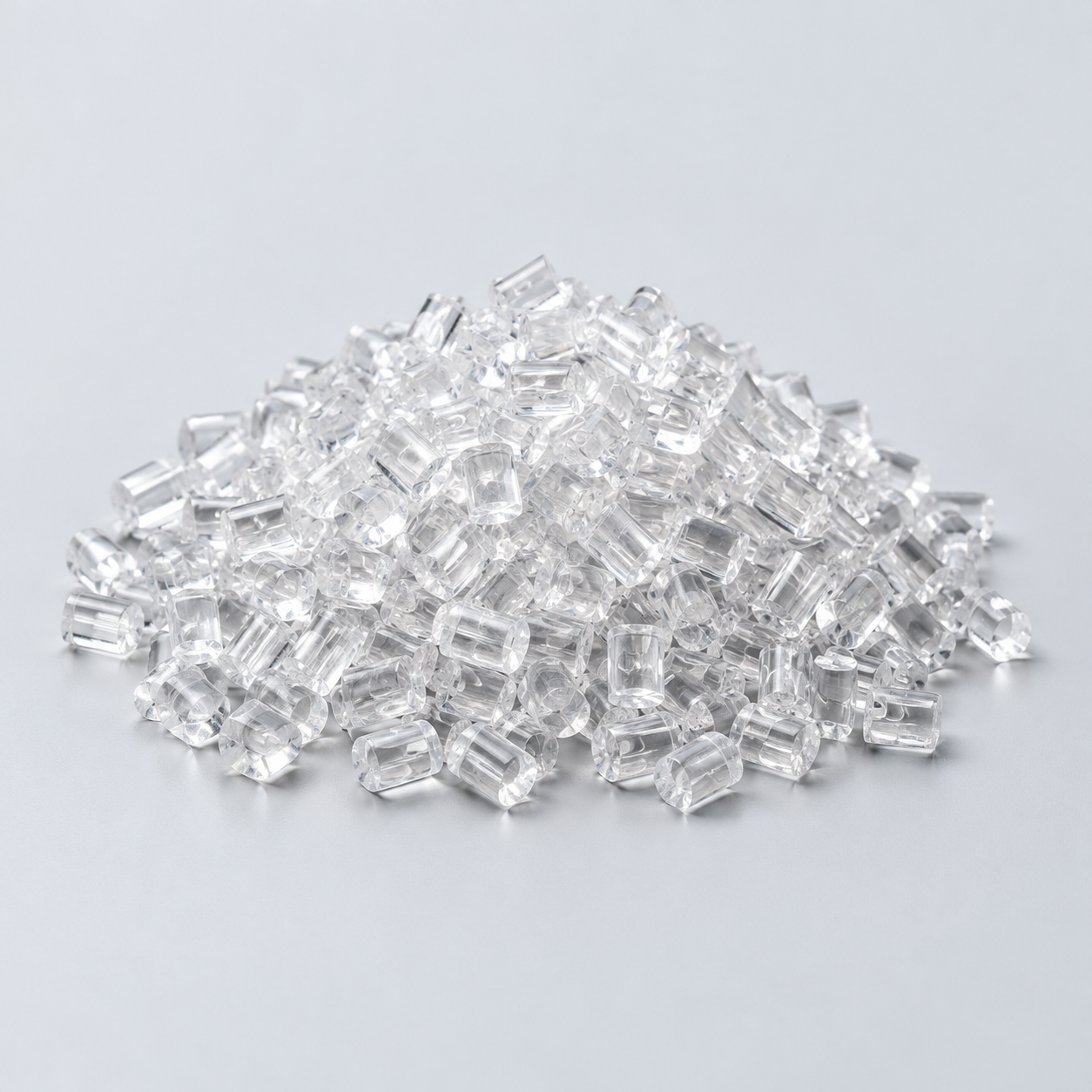 Polycarbonate (PC)Discuss clarity and impact needs›
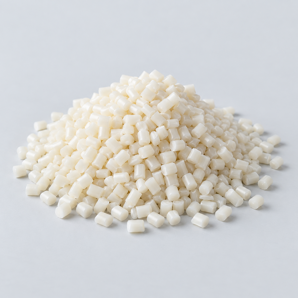 Nylon (PA)Review moisture and wear conditions›
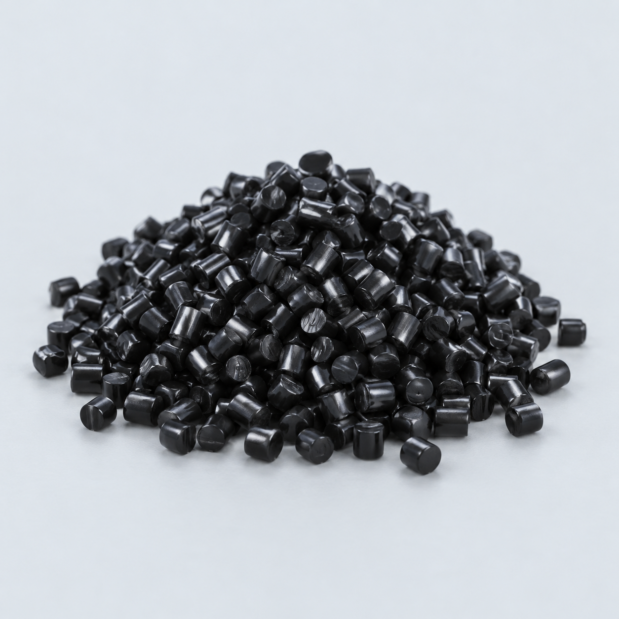 POM / AcetalReview fit and sliding features›
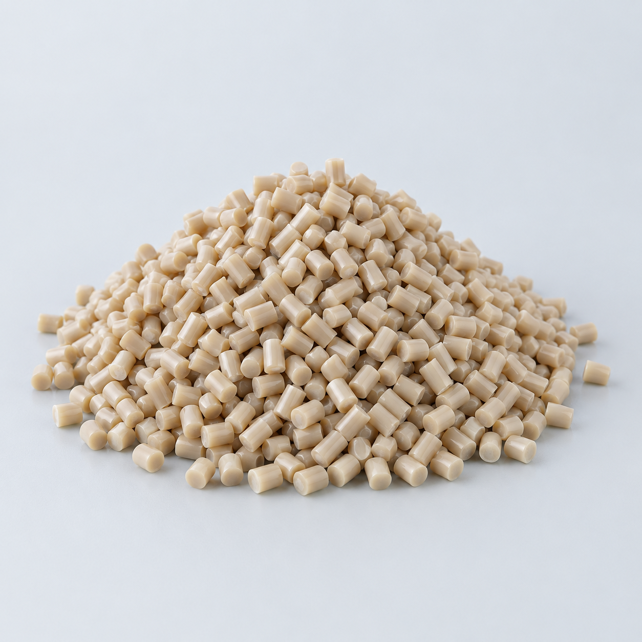 PEEKDiscuss operating conditions›
 PTFEReview friction and chemical exposure›
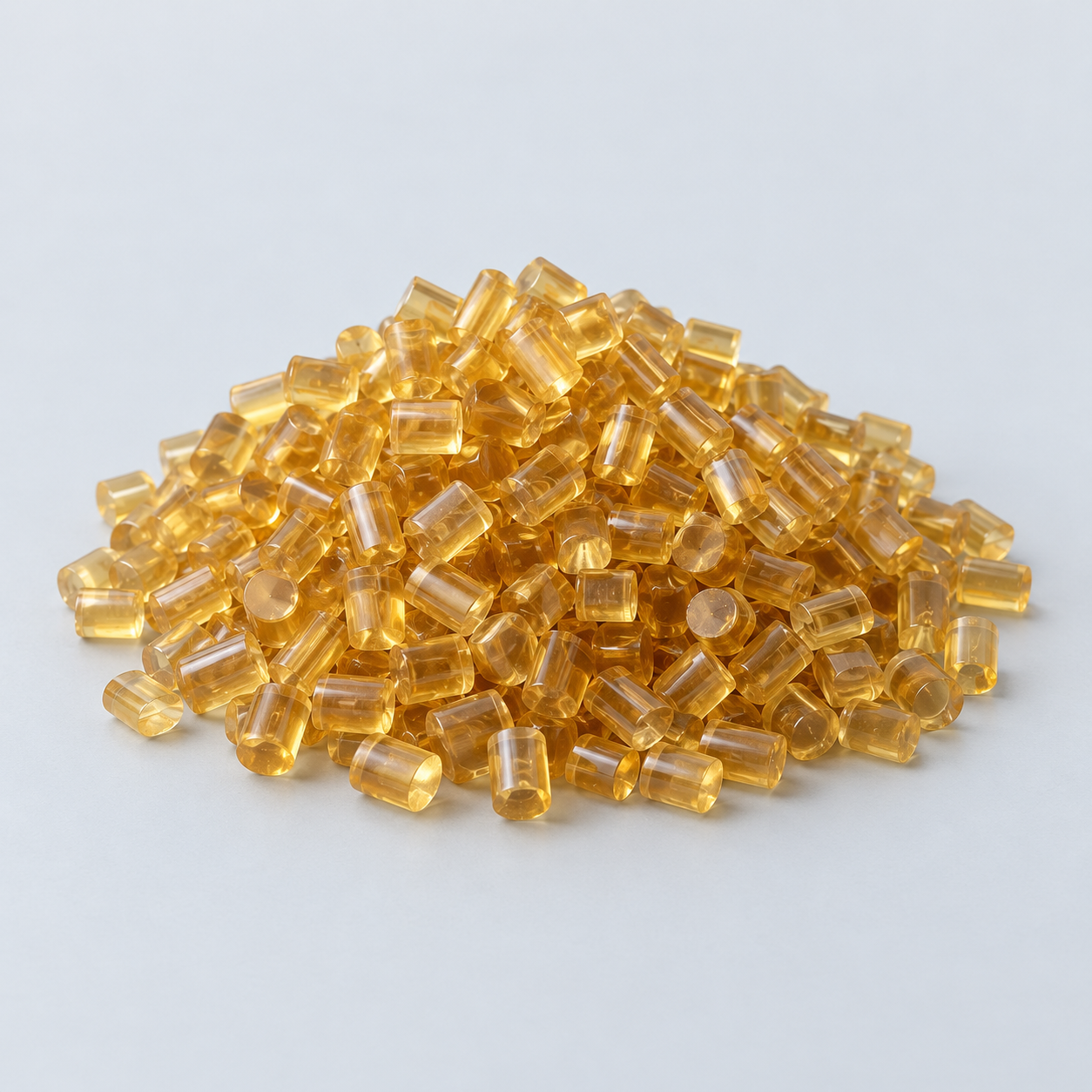 ULTEM / PEIDiscuss thermal and electrical needs›
Confirm grade availability and application requirements.
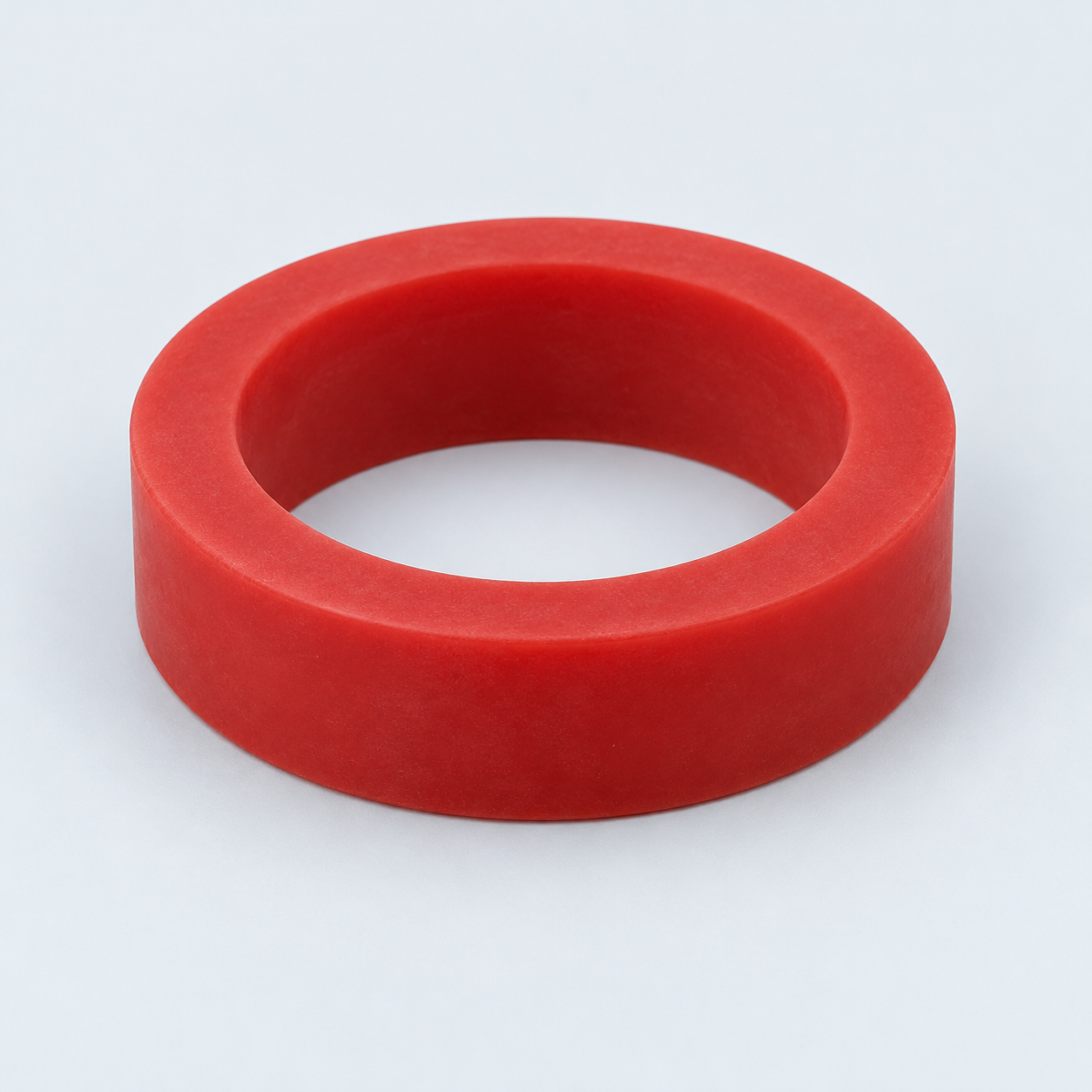 Silicone / LSRDiscuss flexible component needs›
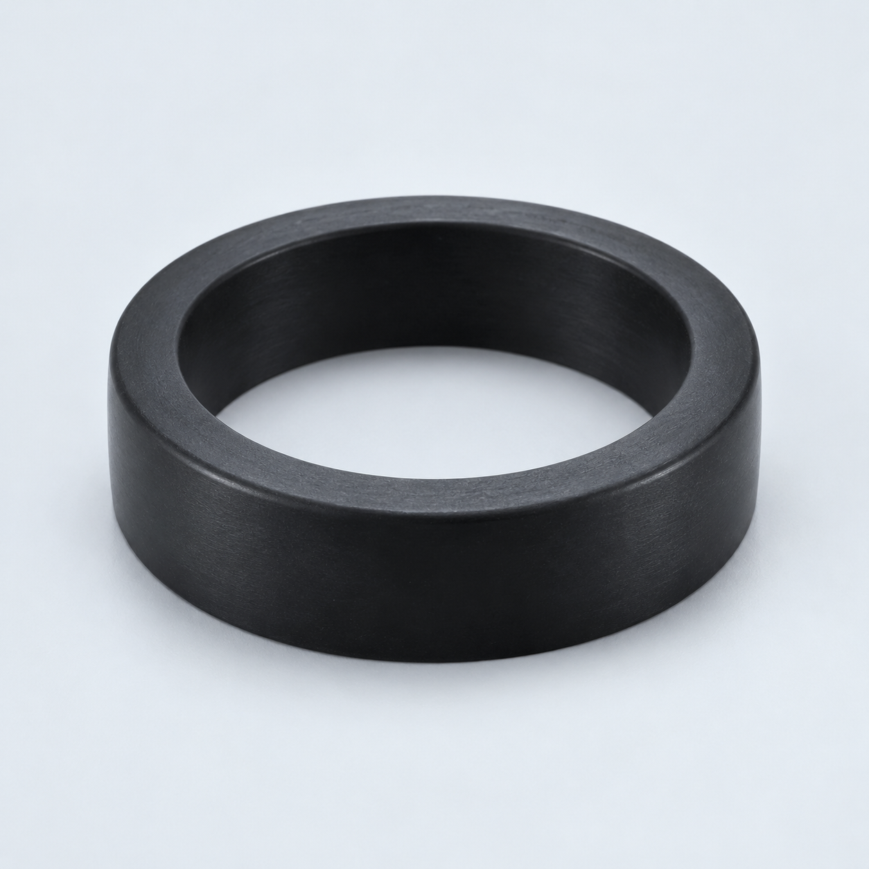 TPU / TPEReview flexibility and processing›
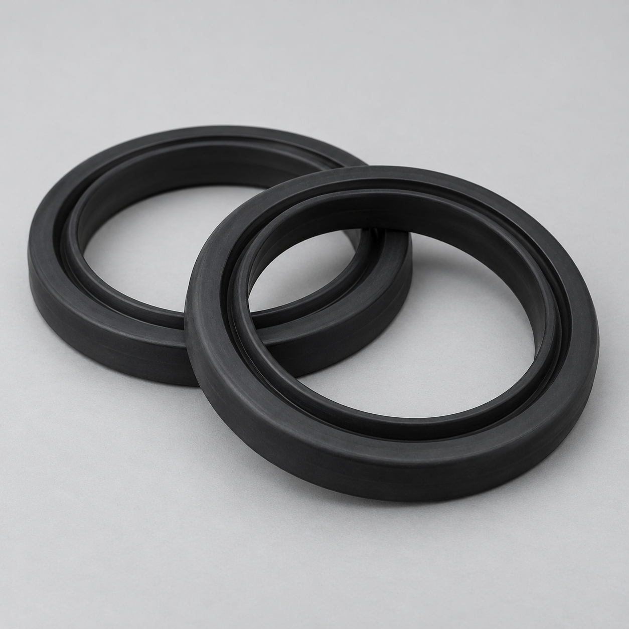 EPDMReview weathering and chemical exposure.›
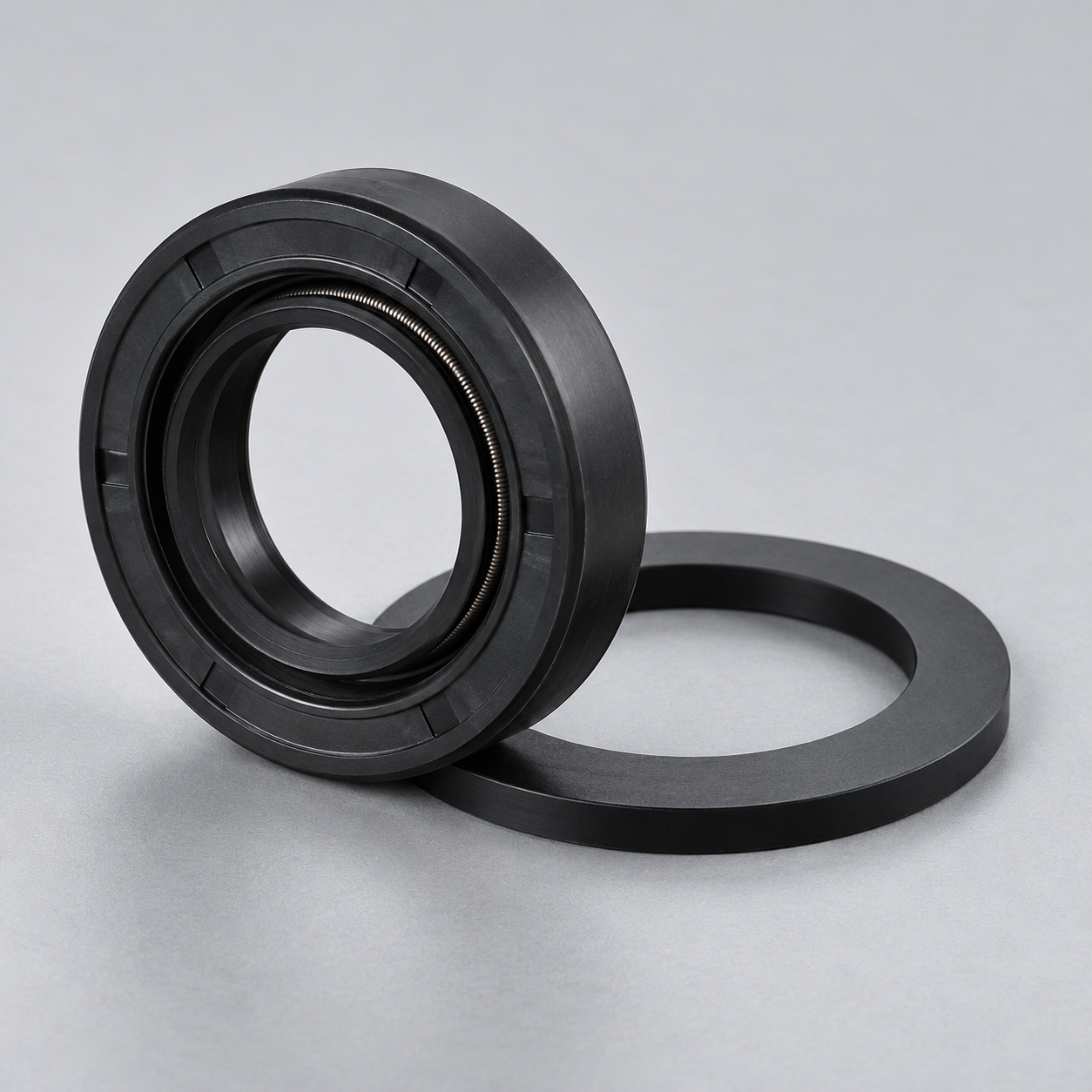 NBRReview oil and fuel exposure.›
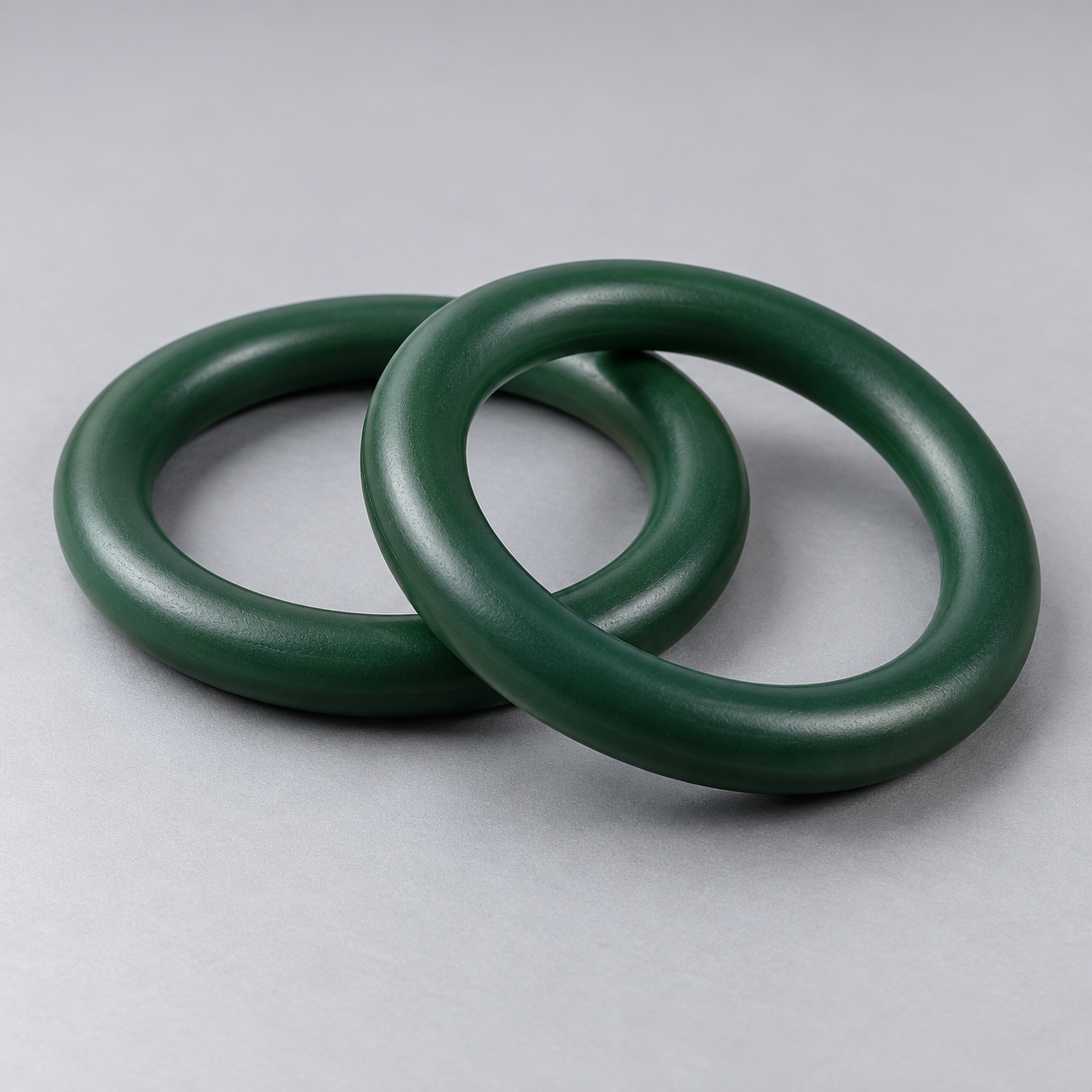 FKMReview temperature and chemical exposure.›
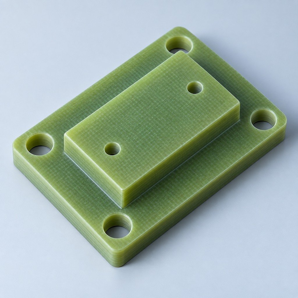 G10 / FR4Review insulation and laminate needs›
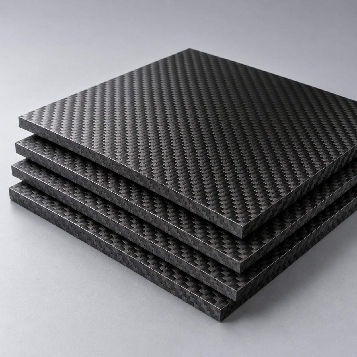 CompositesReview stiffness, weight and laminate.›Customer-Specified MaterialsConfirm your grade and requirements.›Other Specialty MaterialsDiscuss your application and grade.›
Practical guidance for your part geometry and material decisions.
Prepare your process, budget and sourcing questions.
Build your knowledge before production.
Learn who we are and how we operate.
Find our U.S. support team or start a conversation.
BENDING & FORMING
Plan custom sheet metal bending around your grade, thickness and finished dimensions. Review bend sequence, springback and visible faces before production.
Start with 1 formed CAD model + 1 controlled 2D drawing.
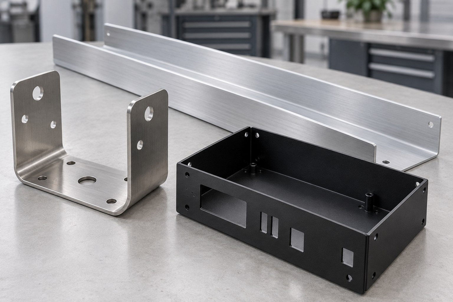
Match your application
Review sequence and access
Check mating dimensions
Define visible faces
Dallas-area support
Define your requirements early so the quote covers your finished part.
Grade, temper, thickness and grain.
Datums, angles and mating features.
Bending only or a finished component.
Press brake forming services use a punch and die to create linear bends. Your tooling and sequence are reviewed for the finished part.
Mark mating holes and final dimensions on your formed drawing.
| Your fit | Mounting holes, mating parts and datums. |
|---|---|
| Bend plan | Inside radius, sequence and tooling access. |
| Your finish | Visible faces, coating and masking. |
Part geometry and manufacturing scope are reviewed with your drawing.
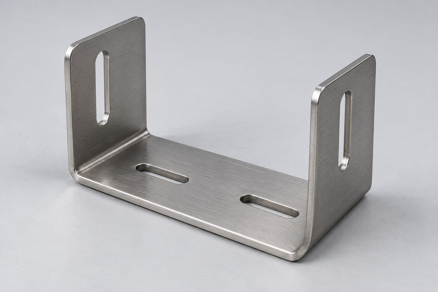
Material suitability depends on the specified grade, condition and geometry.
| Your callout | Exact grade, temper and thickness. |
|---|---|
| Your service conditions | Corrosion, heat and load requirements. |
| Your surface | Grain direction, protective film and finish. |
Part geometry and manufacturing scope are reviewed with your drawing.
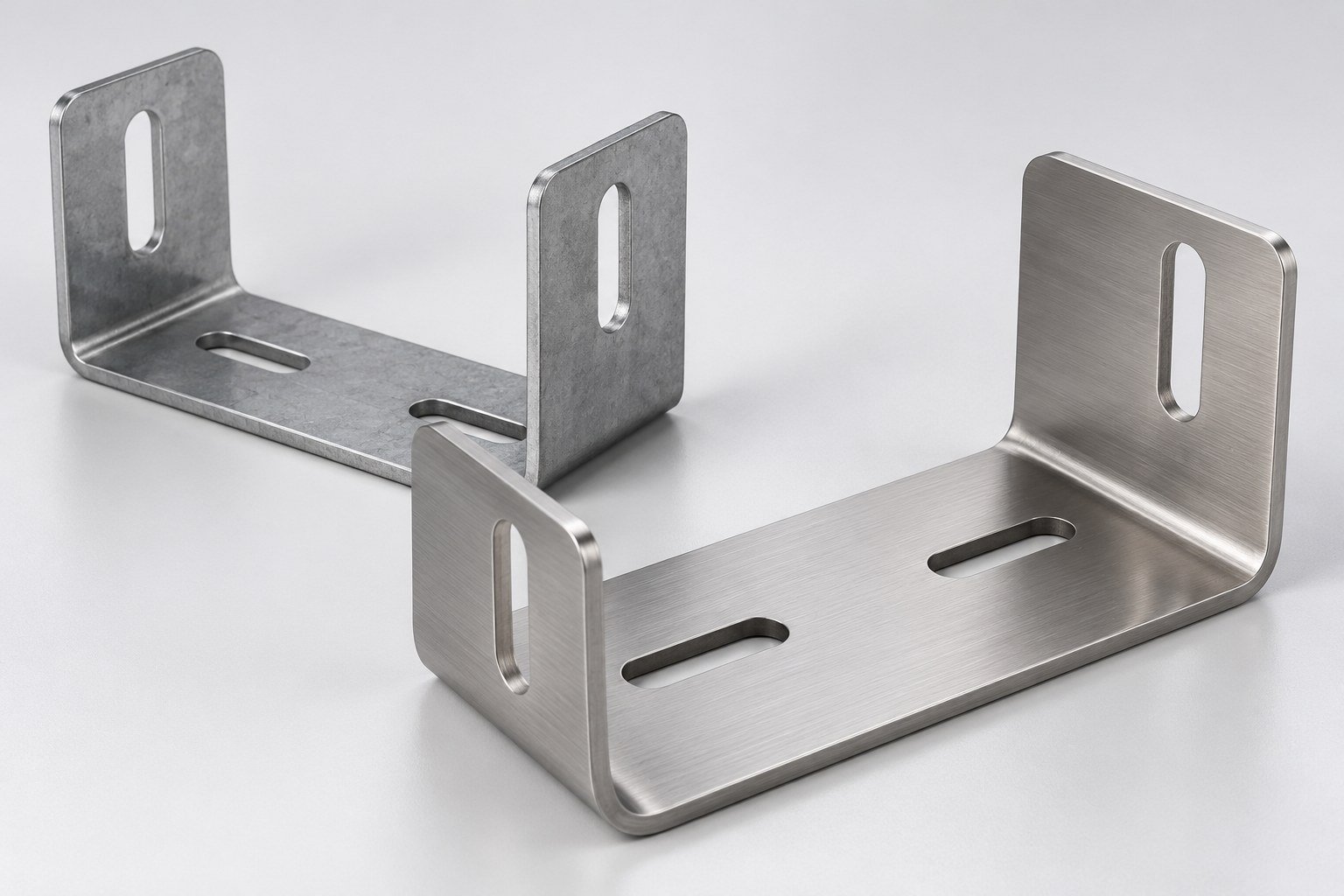
Review the tool approach and bend sequence before releasing the blank.
| Your input | Formed model and controlled dimensions. |
|---|---|
| Our review | Bend order, flange reach and collision risks. |
| Your approval | Agree any radius, relief or flat-pattern changes. |
Part geometry and manufacturing scope are reviewed with your drawing.
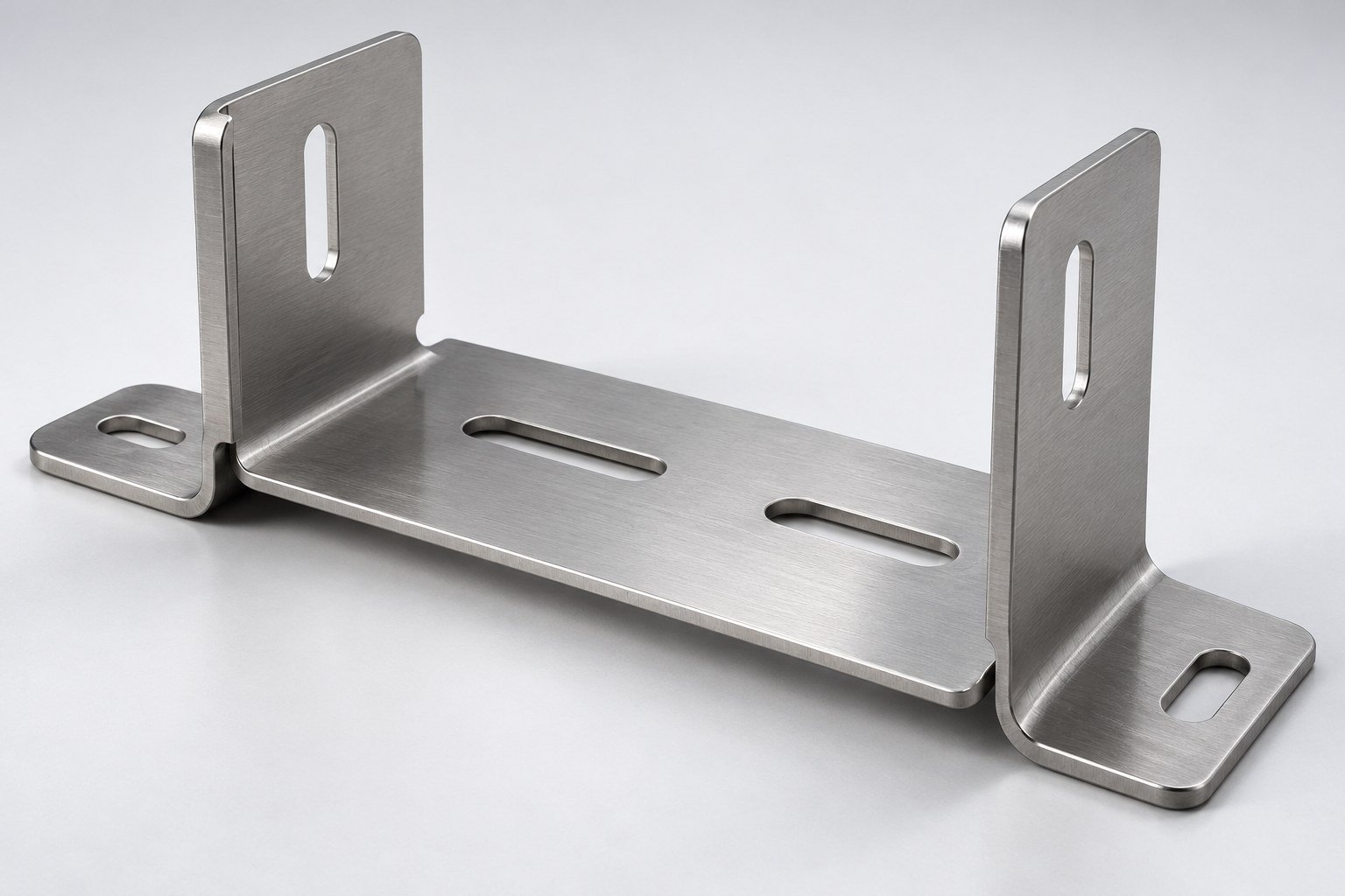
Use the formed part and intended assembly to define acceptance.
| Your dimensions | Angles, flange lengths and hole relationships. |
|---|---|
| Your measurement | Datums, fixture and inspection state. |
| Your sample | Agree checks before repeat production. |
Part geometry and manufacturing scope are reviewed with your drawing.
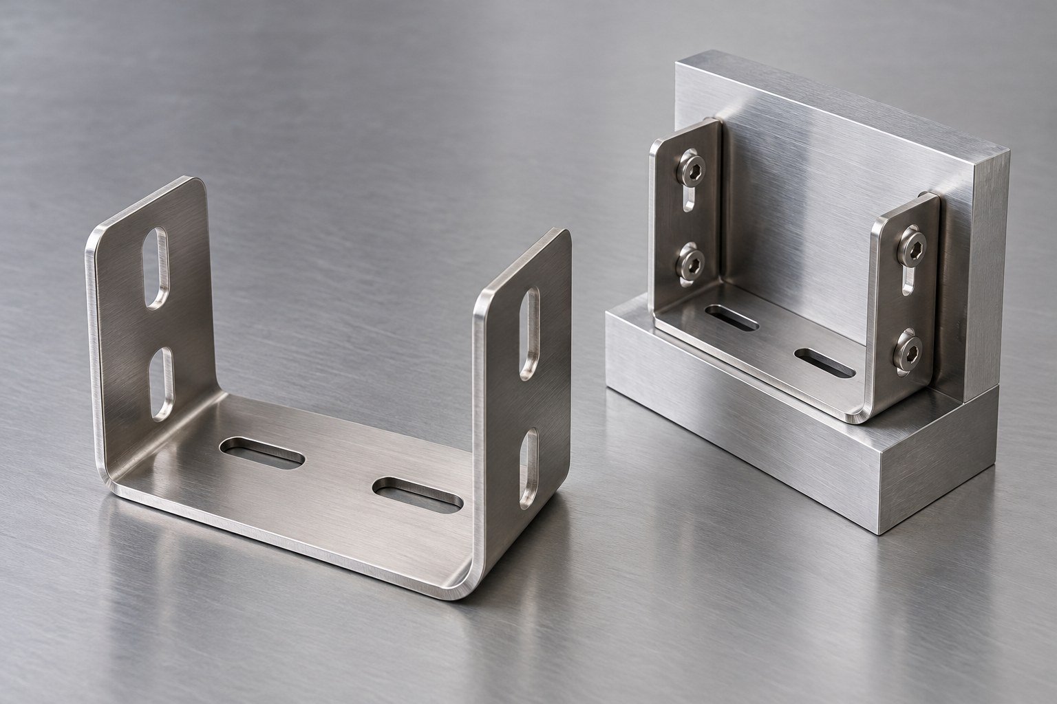
Define fastener positions, mating panels and the faces your customer sees.
| Your fit | Mounting holes, mating parts and datums. |
|---|---|
| Bend plan | Inside radius, sequence and tooling access. |
| Your finish | Visible faces, coating and masking. |
Part geometry and manufacturing scope are reviewed with your drawing.
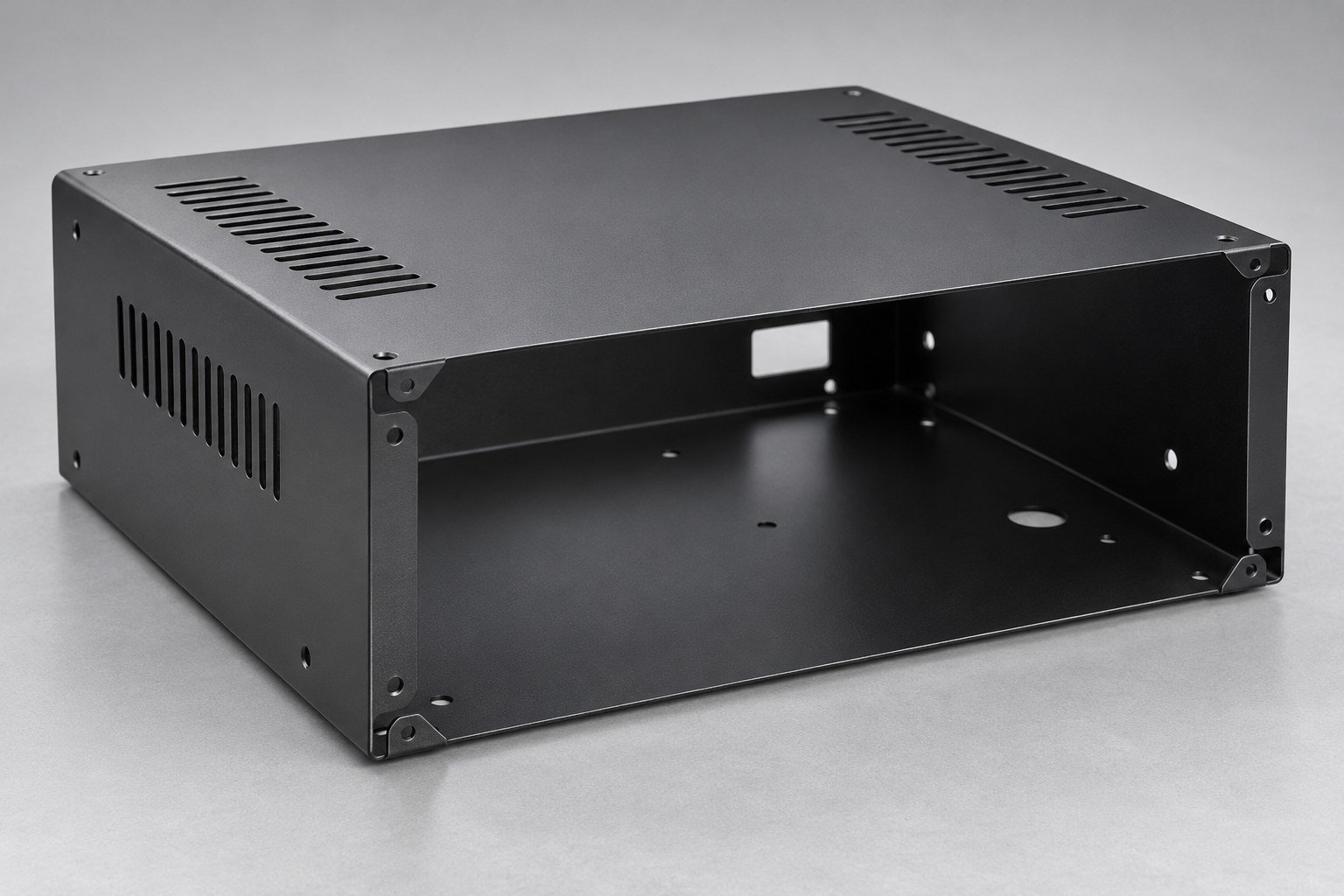
Material suitability depends on the specified grade, condition and geometry.
| Your callout | Exact grade, temper and thickness. |
|---|---|
| Your service conditions | Corrosion, heat and load requirements. |
| Your surface | Grain direction, protective film and finish. |
Part geometry and manufacturing scope are reviewed with your drawing.
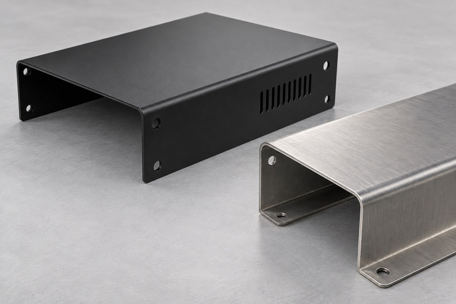
Review the tool approach and bend sequence before releasing the blank.
| Your input | Formed model and controlled dimensions. |
|---|---|
| Our review | Bend order, flange reach and collision risks. |
| Your approval | Agree any radius, relief or flat-pattern changes. |
Part geometry and manufacturing scope are reviewed with your drawing.
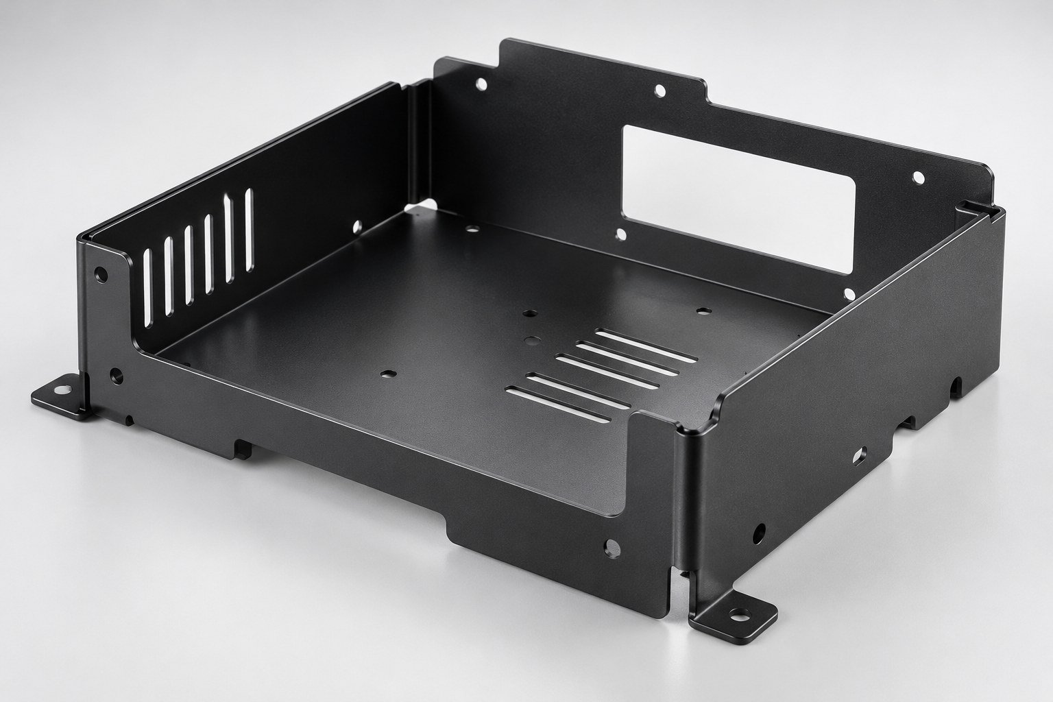
Use the formed part and intended assembly to define acceptance.
| Your dimensions | Angles, flange lengths and hole relationships. |
|---|---|
| Your measurement | Datums, fixture and inspection state. |
| Your sample | Agree checks before repeat production. |
Part geometry and manufacturing scope are reviewed with your drawing.
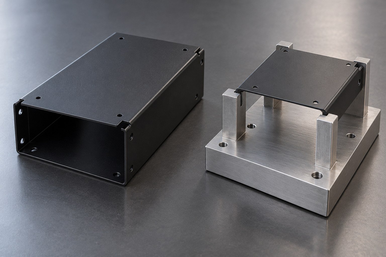
Review flange dimensions, mounting slots and straightness in the assembled state.
| Your fit | Mounting holes, mating parts and datums. |
|---|---|
| Bend plan | Inside radius, sequence and tooling access. |
| Your finish | Visible faces, coating and masking. |
Part geometry and manufacturing scope are reviewed with your drawing.
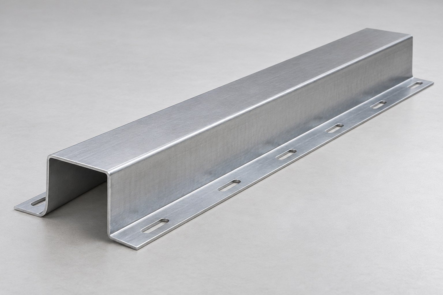
Material suitability depends on the specified grade, condition and geometry.
| Your callout | Exact grade, temper and thickness. |
|---|---|
| Your service conditions | Corrosion, heat and load requirements. |
| Your surface | Grain direction, protective film and finish. |
Part geometry and manufacturing scope are reviewed with your drawing.
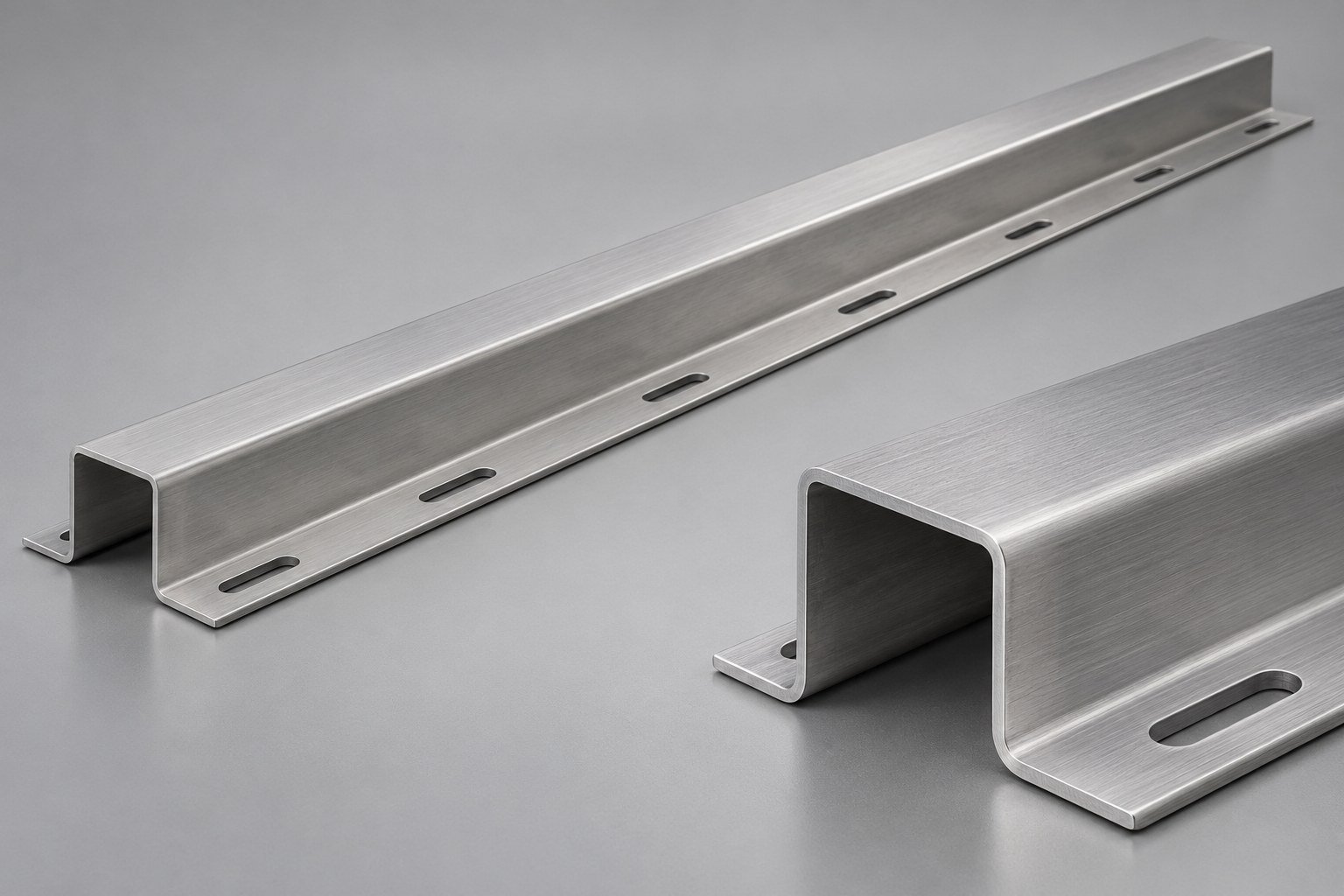
Review the tool approach and bend sequence before releasing the blank.
| Your input | Formed model and controlled dimensions. |
|---|---|
| Our review | Bend order, flange reach and collision risks. |
| Your approval | Agree any radius, relief or flat-pattern changes. |
Part geometry and manufacturing scope are reviewed with your drawing.
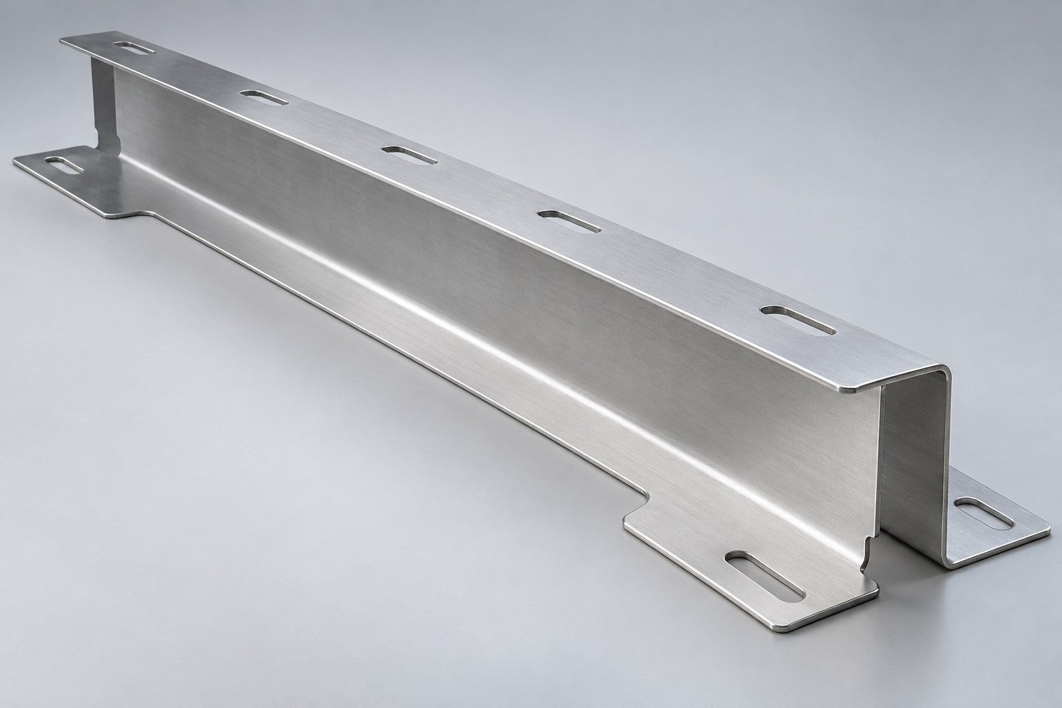
Use the formed part and intended assembly to define acceptance.
| Your dimensions | Angles, flange lengths and hole relationships. |
|---|---|
| Your measurement | Datums, fixture and inspection state. |
| Your sample | Agree checks before repeat production. |
Part geometry and manufacturing scope are reviewed with your drawing.
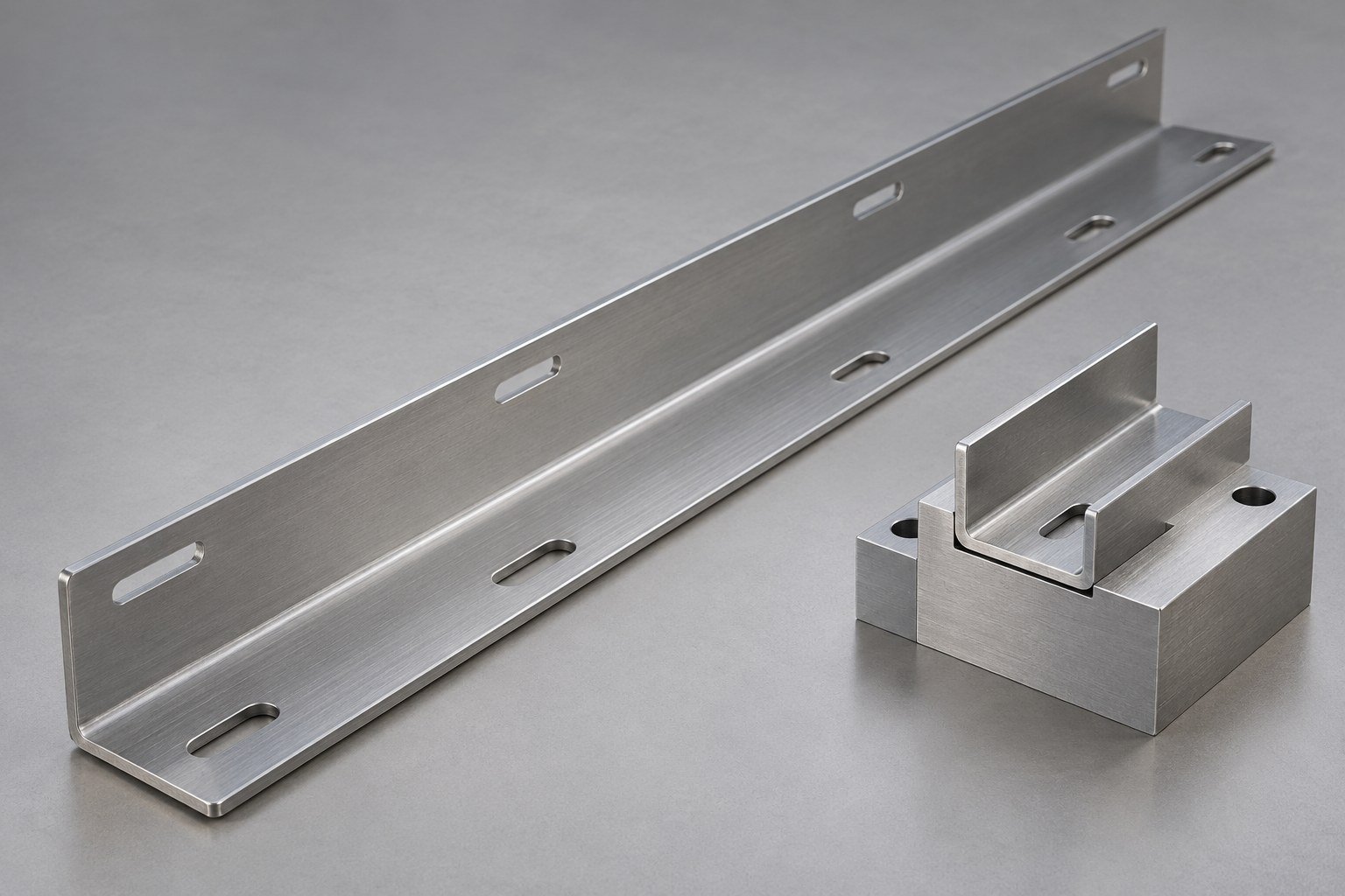
Identify clearances, fastening points and the protected cosmetic faces.
| Your fit | Mounting holes, mating parts and datums. |
|---|---|
| Bend plan | Inside radius, sequence and tooling access. |
| Your finish | Visible faces, coating and masking. |
Part geometry and manufacturing scope are reviewed with your drawing.
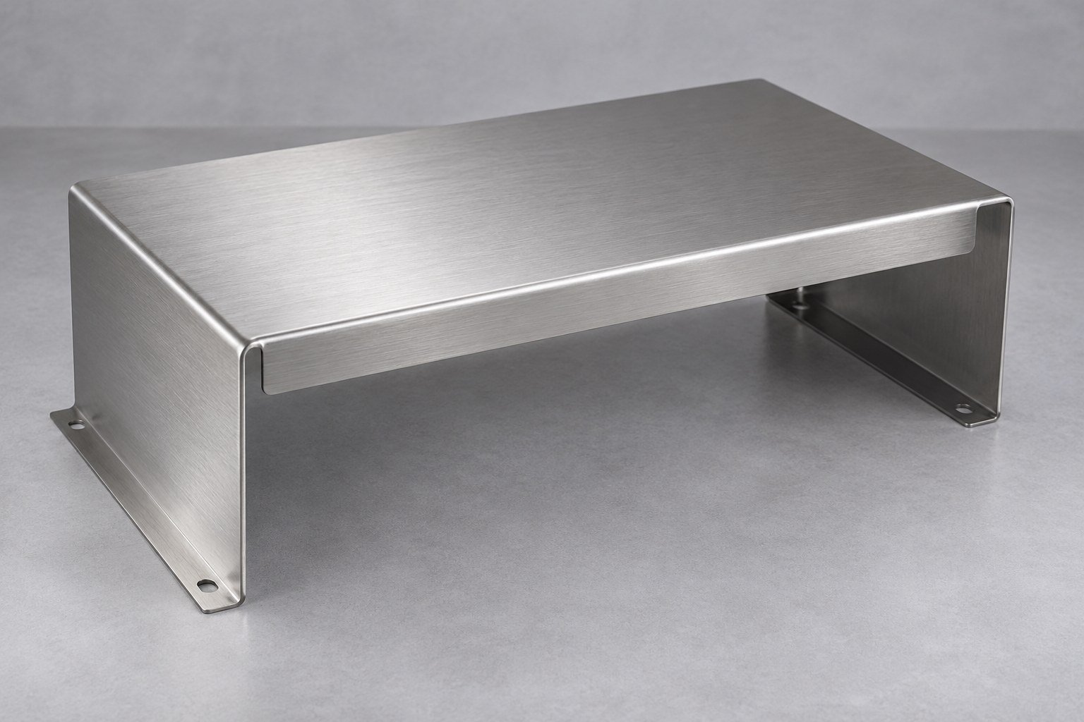
Material suitability depends on the specified grade, condition and geometry.
| Your callout | Exact grade, temper and thickness. |
|---|---|
| Your service conditions | Corrosion, heat and load requirements. |
| Your surface | Grain direction, protective film and finish. |
Part geometry and manufacturing scope are reviewed with your drawing.
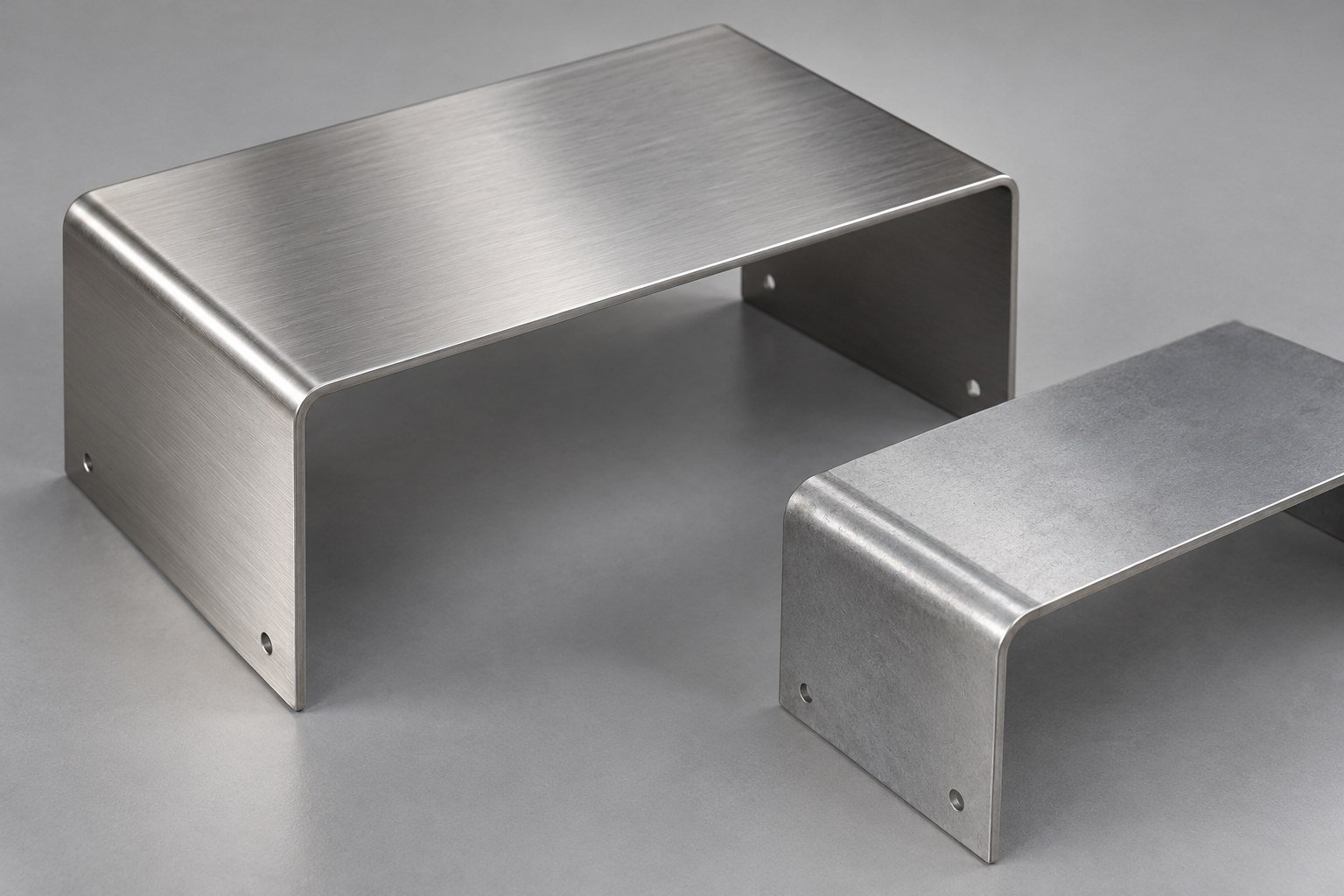
Review the tool approach and bend sequence before releasing the blank.
| Your input | Formed model and controlled dimensions. |
|---|---|
| Our review | Bend order, flange reach and collision risks. |
| Your approval | Agree any radius, relief or flat-pattern changes. |
Part geometry and manufacturing scope are reviewed with your drawing.
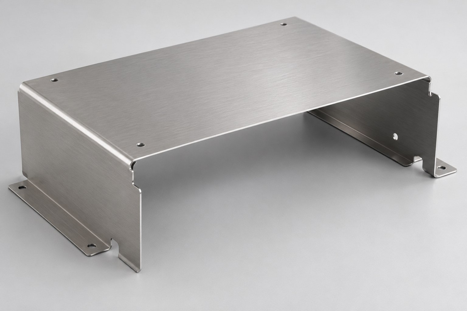
Use the formed part and intended assembly to define acceptance.
| Your dimensions | Angles, flange lengths and hole relationships. |
|---|---|
| Your measurement | Datums, fixture and inspection state. |
| Your sample | Agree checks before repeat production. |
Part geometry and manufacturing scope are reviewed with your drawing.
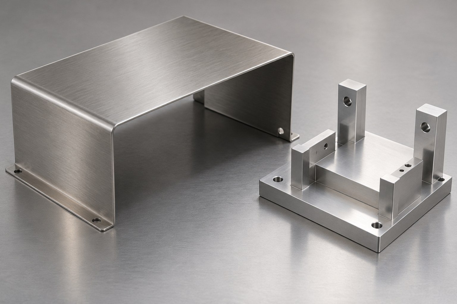
Sheet metal forming services on this page focus on press-brake bends.
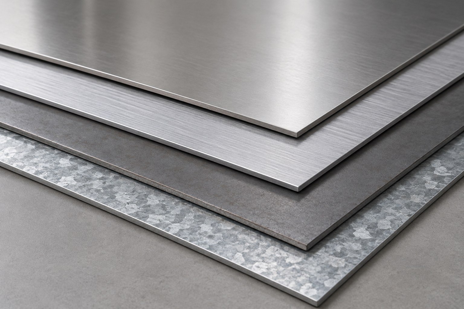
| Material | What Your Review Should Confirm |
|---|---|
| Aluminum | Confirm alloy, temper, grain direction and inside bend radius. |
| Stainless Steel | Review grade, springback and cosmetic grain. |
| Carbon / Mild Steel | Specify grade, thickness and post-form finish. |
| Galvanized Steel | Confirm coating condition and allowable marks. |
Material, thickness and formed size are confirmed for your drawing.
CNC press brake bending follows an agreed setup and first-part review.
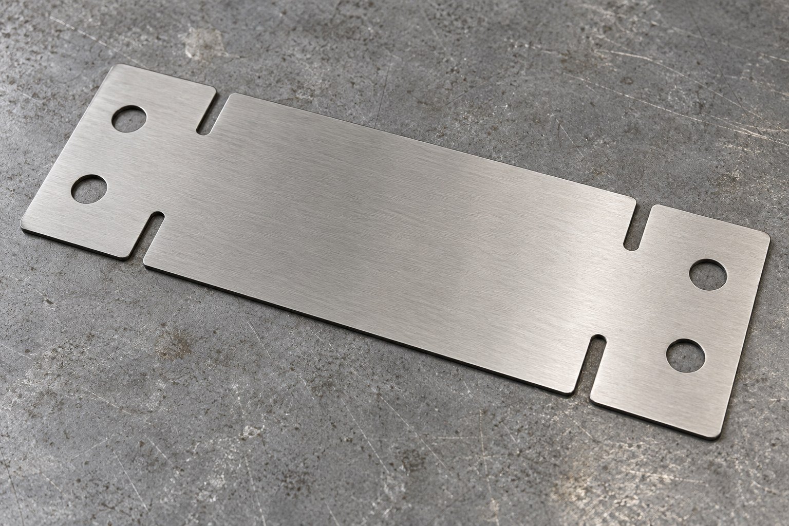
Blank cut to shape with holes and reliefs.
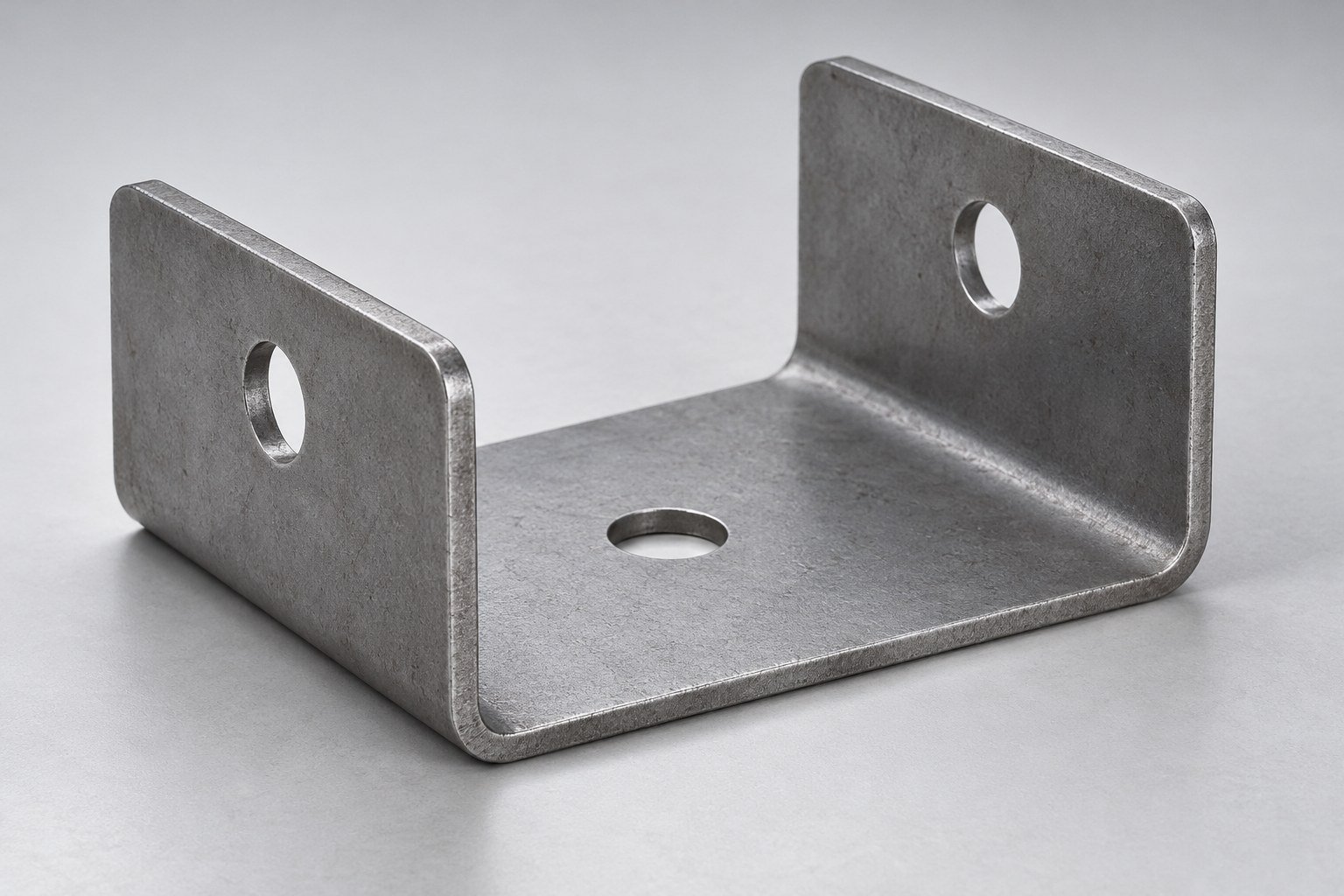
Formed to drawing and checked.
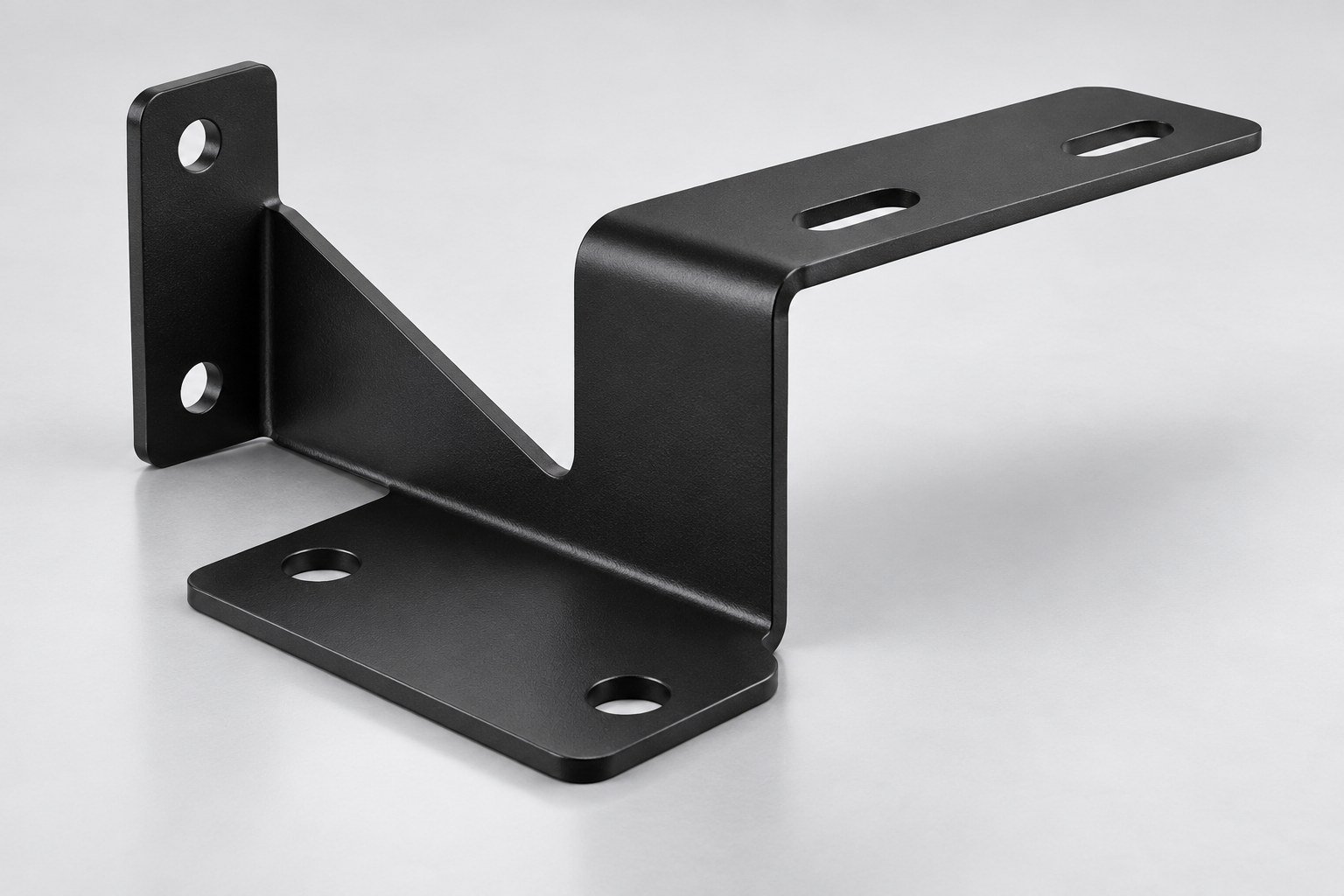
Coated or other finish as specified.
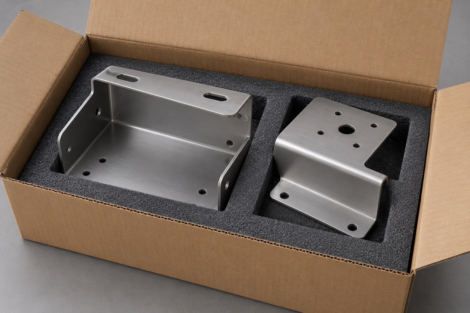
Checked and protected for delivery.
* Secondary work is included only when specified in your quote.
Use these sheet metal bending design guidelines to review your formed part.
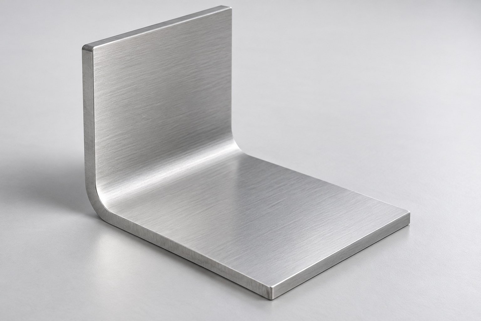
Review alloy, temper, thickness and grain direction before selecting the inside bend radius.
| Your input | Grade, temper, thickness and grain. |
|---|---|
| Our review | Inside radius and cracking risk. |
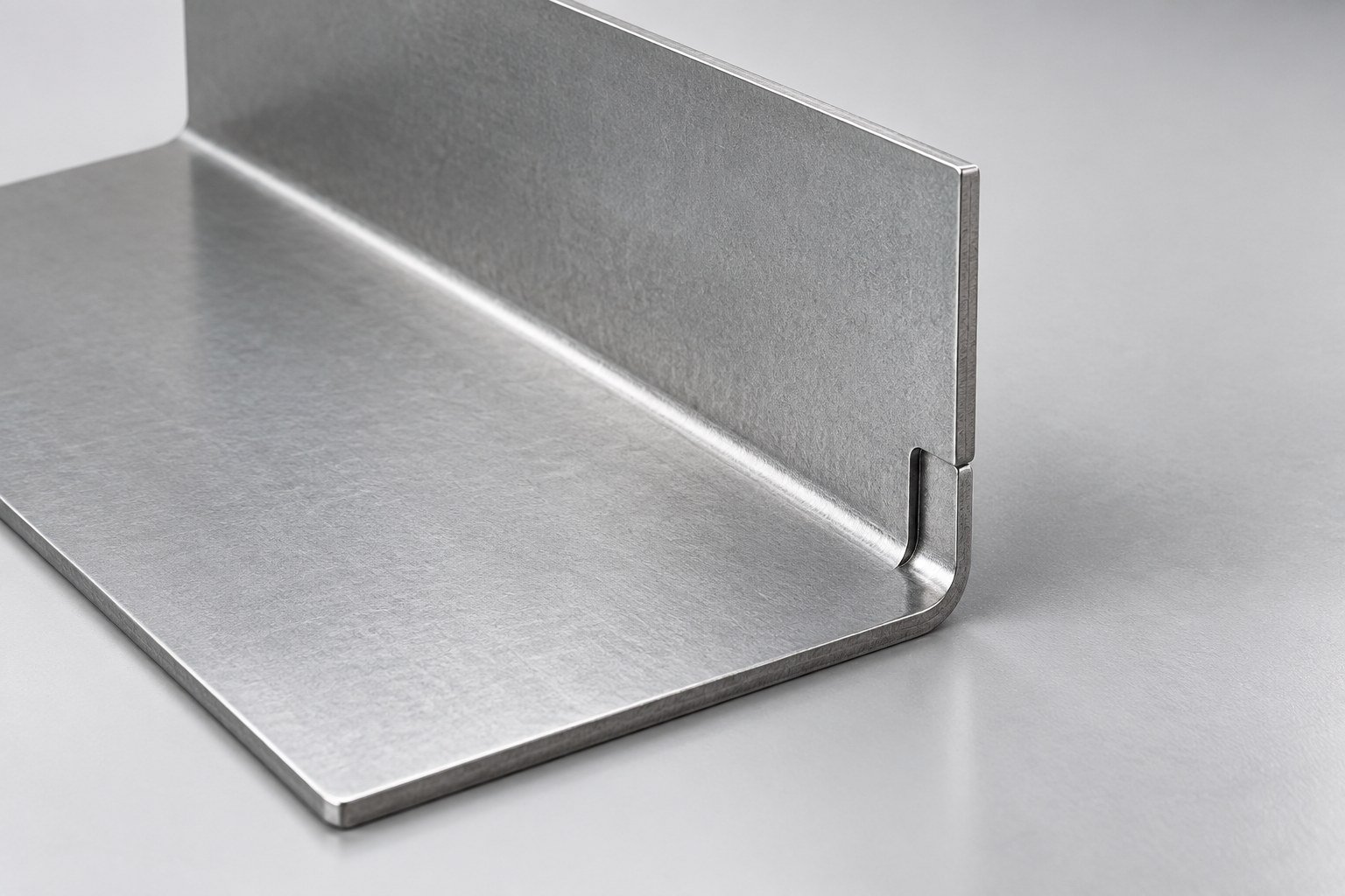
Review hole-to-bend distance and sheet metal bend relief where flanges meet.
| Your input | Hole positions and corner geometry. |
|---|---|
| Our review | Deformation risk and relief access. |
Review sheet metal springback against your finished angle and mating geometry.
ILLUSTRATION ONLY — NOT AN LK TOLERANCE
Idealized flange rotation. Actual geometry and measurement datums must be defined.
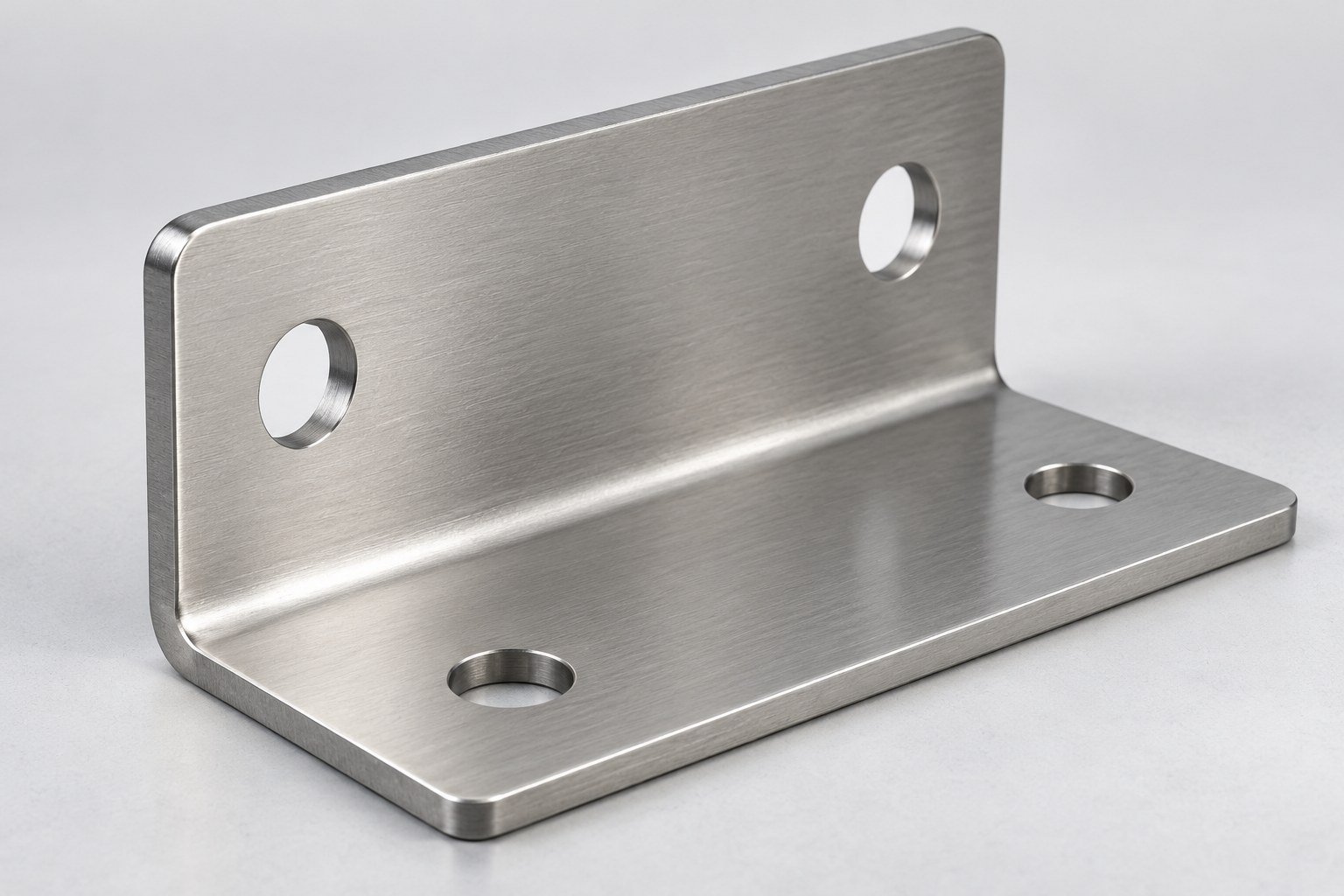
Consider punch and die approach, short flanges, return bends and part collisions.
| Your input | Full formed model and mating parts. |
|---|---|
| Our review | Sequence, reach and tool clearance. |
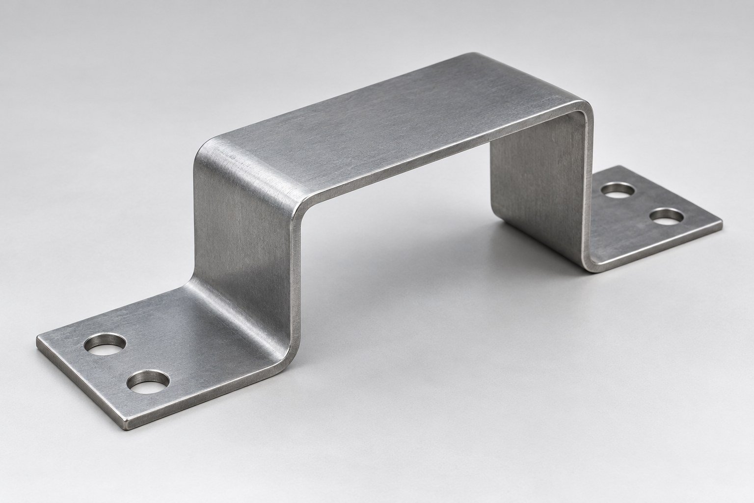
The formed model defines the finished part. Agree the flat-pattern revision and bend development.
| Your input | Formed CAD plus any supplied DXF. |
|---|---|
| Our review | Bend allowance, reliefs and revision control. |
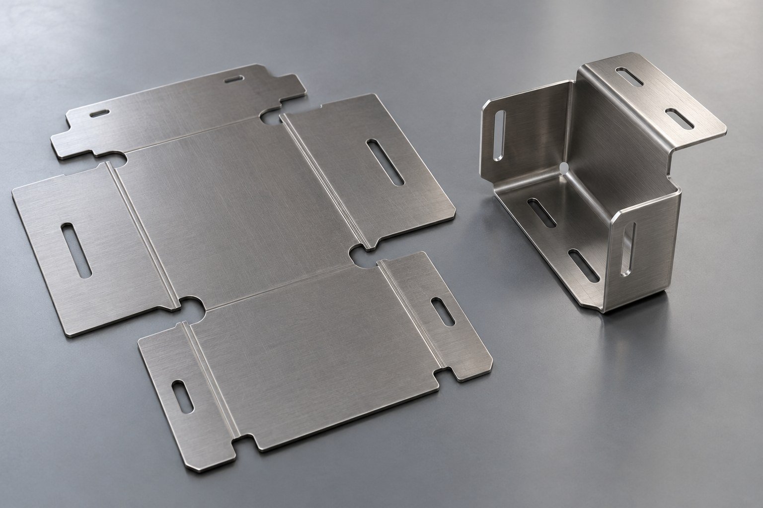
Identify visible faces before tooling and handling are planned.
| Your input | Cosmetic zones and accepted sample. |
|---|---|
| Our review | Tool marks, film and post-form finish. |
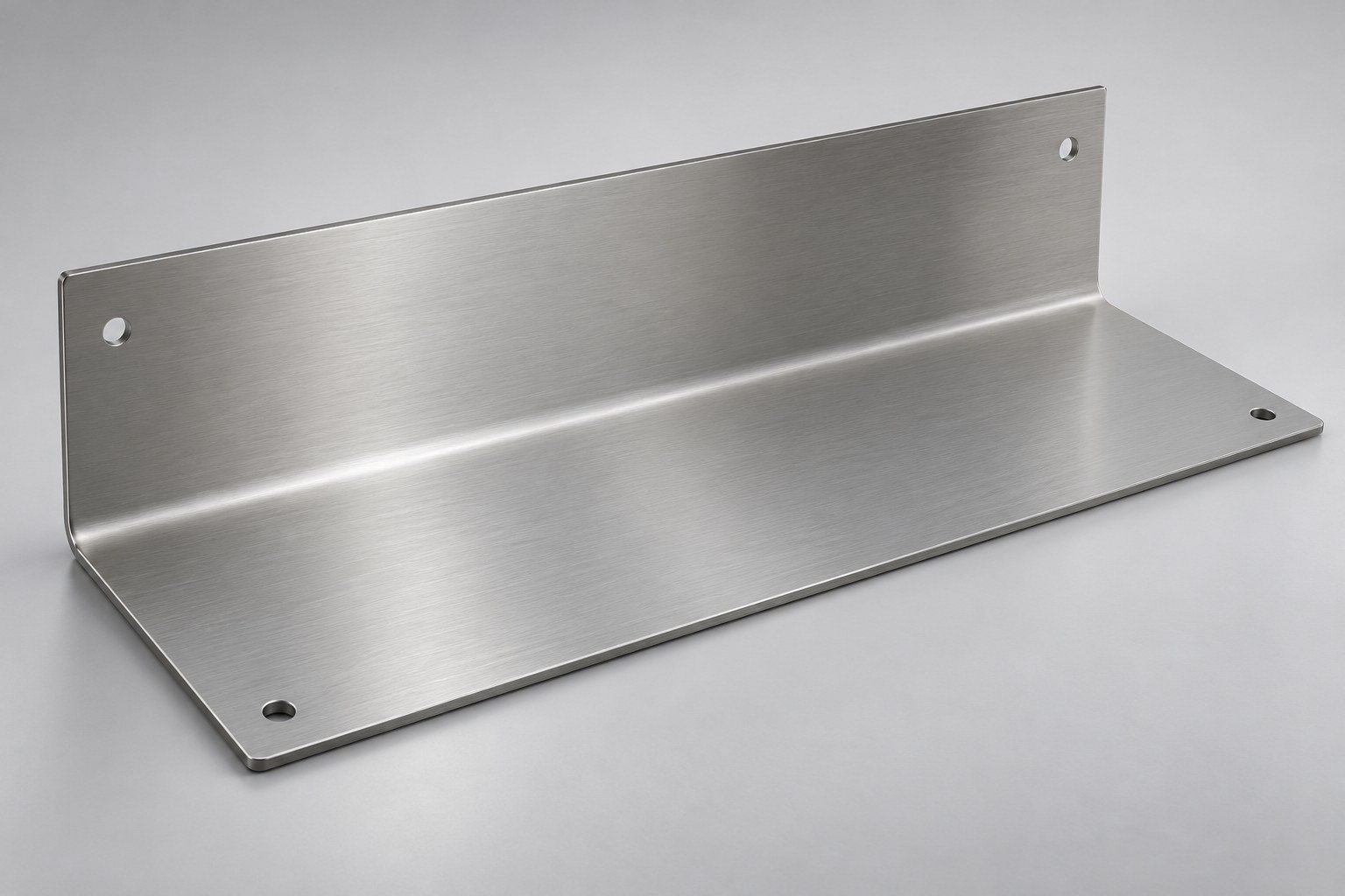
Set sheet metal bending tolerances by feature and inspection state.
| Part state | What Your Drawing Should Define |
|---|---|
| Flat Blank | Cut profile, holes and flat-pattern revision. |
| Formed Part | Angles, flange dimensions and hole relationships. |
| Finished Part | Coated fits, hardware and assembly clearances. |
Agree datums, fixture conditions and inspection methods. No single tolerance applies to every feature.
Review the specified material, thickness and drawing revision.
Report format, sampling and acceptance scope are agreed in your quote.
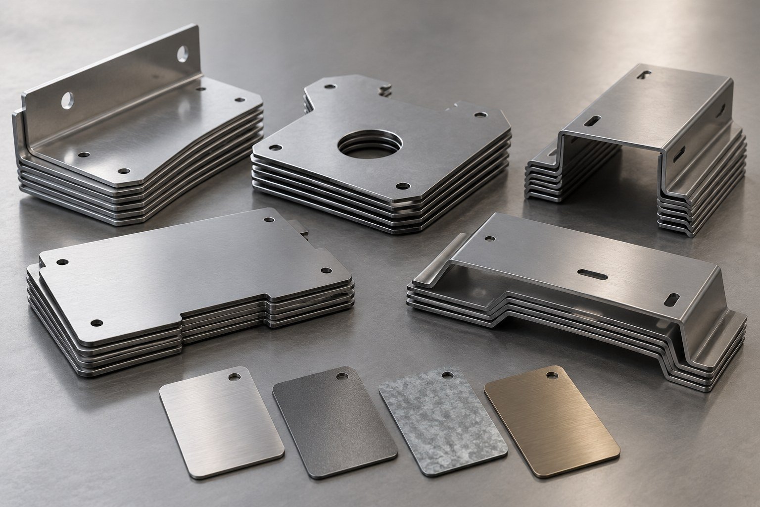
Plan prototype sheet metal forming around agreed fit, finish and functional checks.
Report format, sampling and acceptance scope are agreed in your quote.
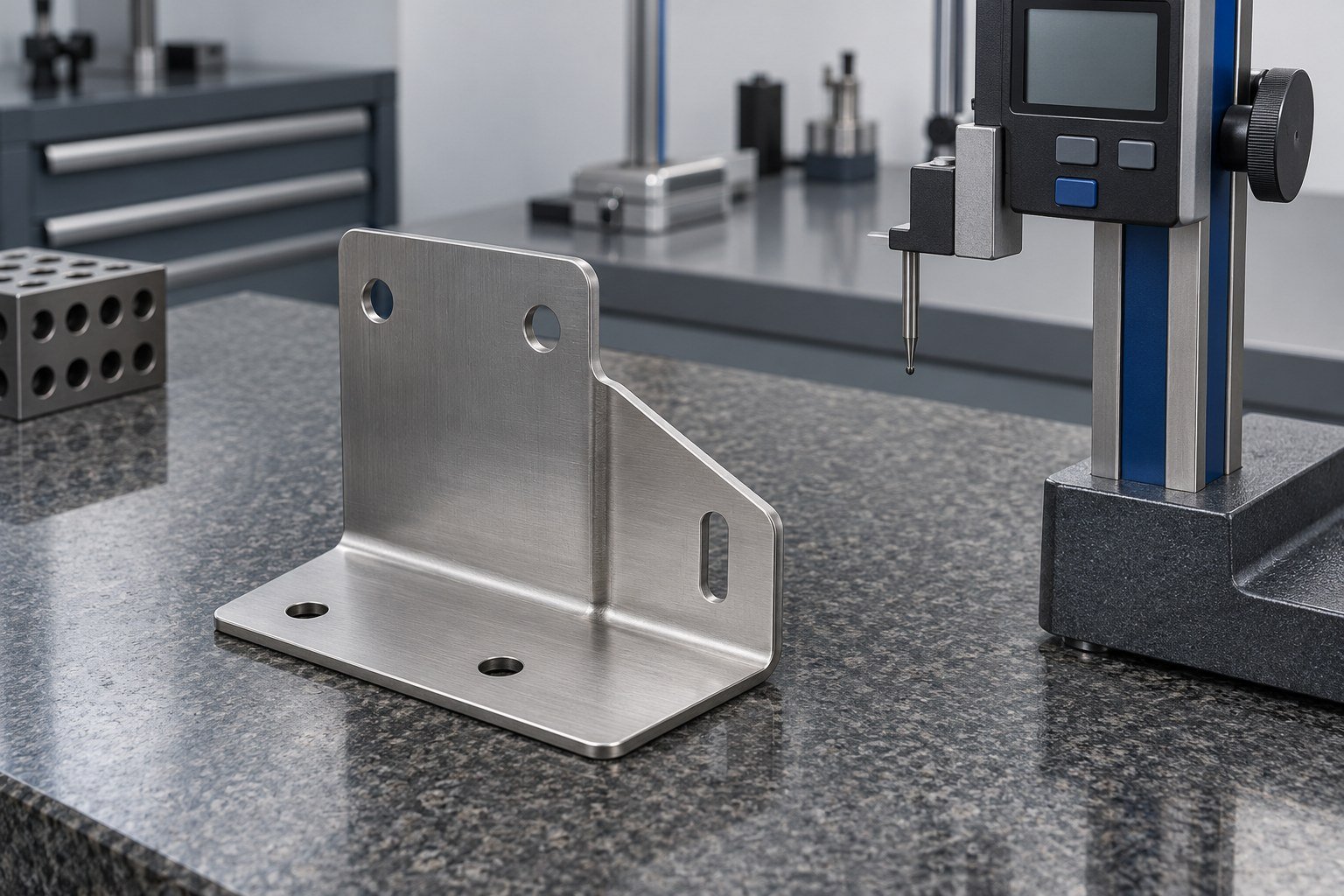
Check selected dimensions and appearance during the agreed production stages.
Report format, sampling and acceptance scope are agreed in your quote.
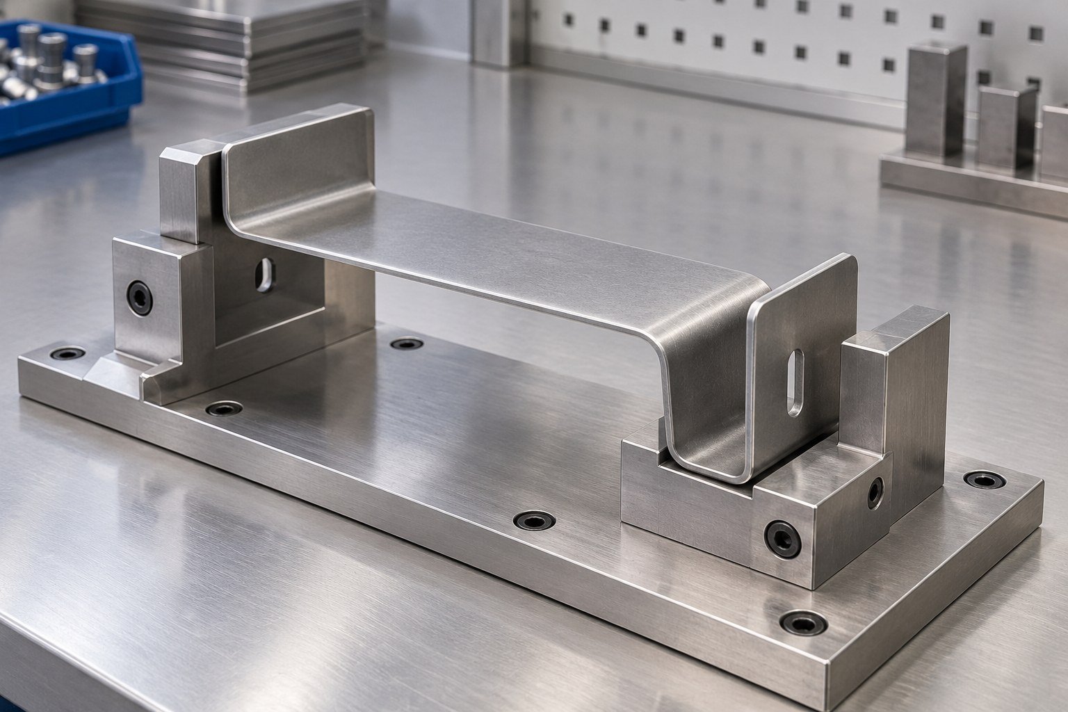
Review acceptance results, part protection and shipment identification.
Report format, sampling and acceptance scope are agreed in your quote.
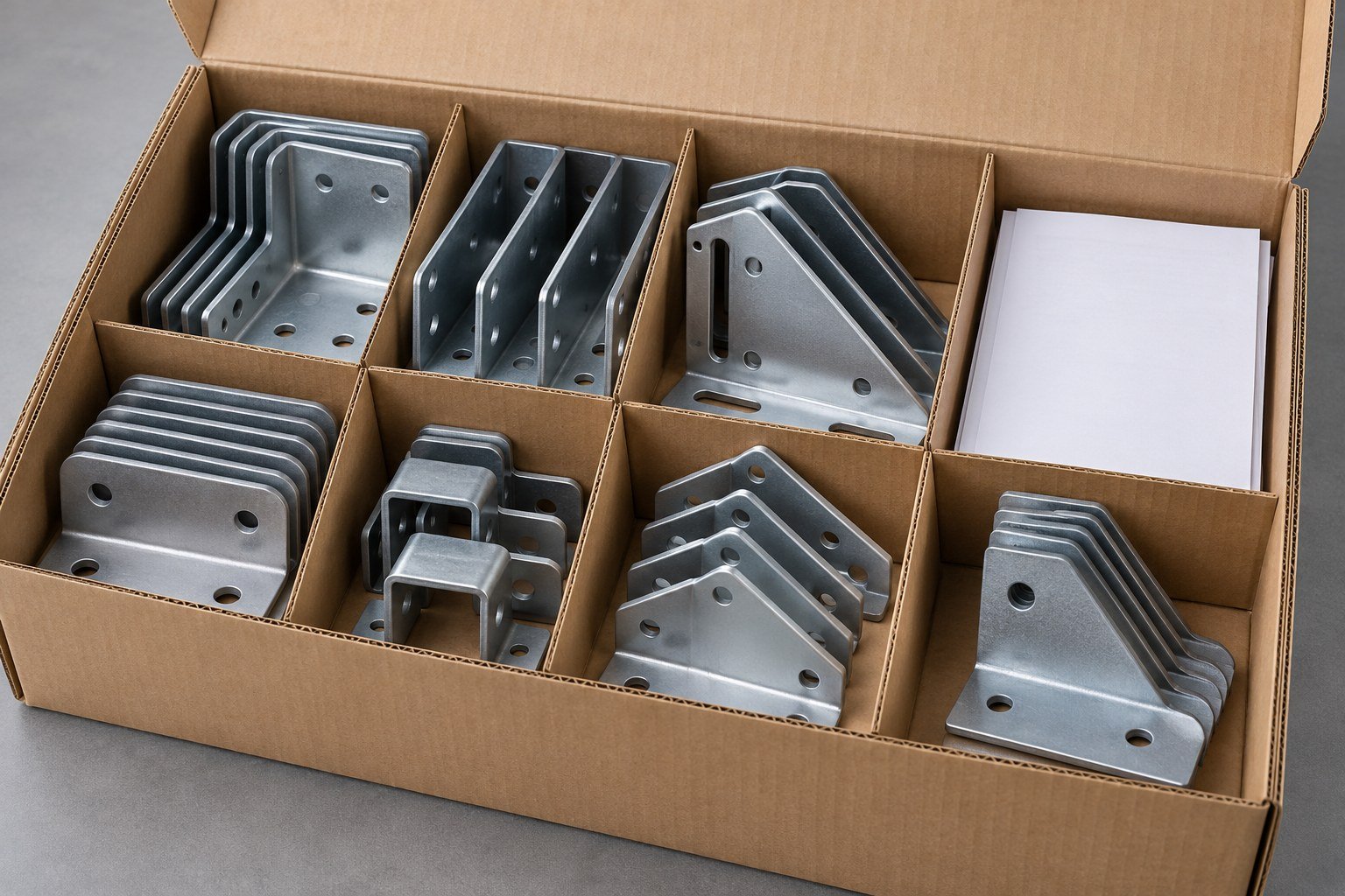
For low volume sheet metal bending, separate setup from repeat part cost.
RFQ EXAMPLES — NOT MINIMUM ORDERS
Replace with your actual demand.
Agree blank supply, special-tool ownership and revision approval.

Coordinate your drawing review, sample approval and delivery requirements.
It is the neutral-axis length within a bend used to develop the flat pattern. Confirm the material, thickness, radius, tooling and who approves the manufacturing flat.
Required clearance depends on thickness, radius, tooling and hole shape. Share the formed drawing so hole distortion can be reviewed. A relief or a post-form operation may be needed.
Agree limits by feature, material and inspection state. Identify the critical angles, datums, flange dimensions and mating hole positions; confirm feasibility before approving production.
Cost depends on blank material, bend count, setup, handling, finish, inspection and quantity. Compare the same drawing revision and finished-part scope at your actual order quantities.
The schedule depends on material availability, setup or special tooling, sample approval, finishing and quantity. Request separate sample and production milestones for your drawing.