Injection Molding
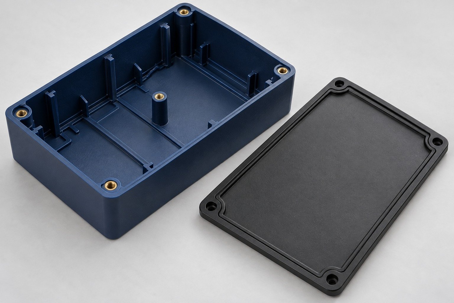
Tooling and molding for your repeat plastic parts.
From prototype to production, coordinated manufacturing solutions for your custom parts.
View All Services →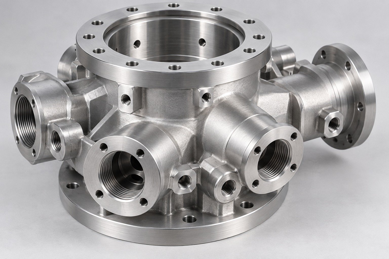
Precision parts for your tight tolerances and complex geometry.
Tooling and molding for your repeat plastic parts.
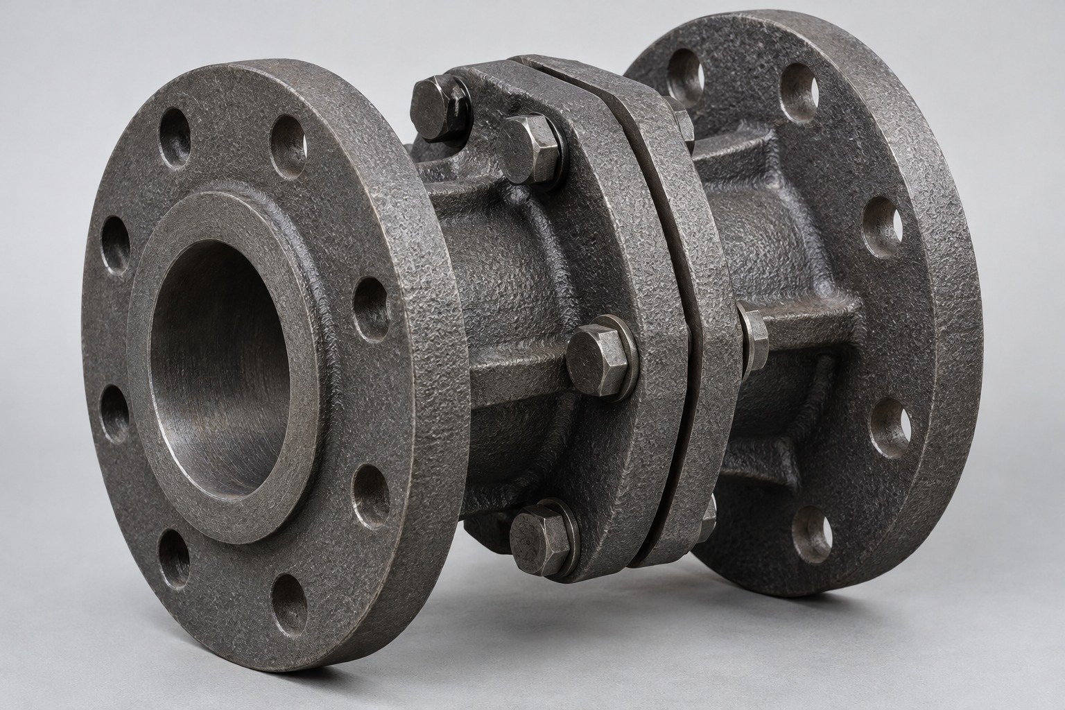
Metal casting options for your part and production volume.
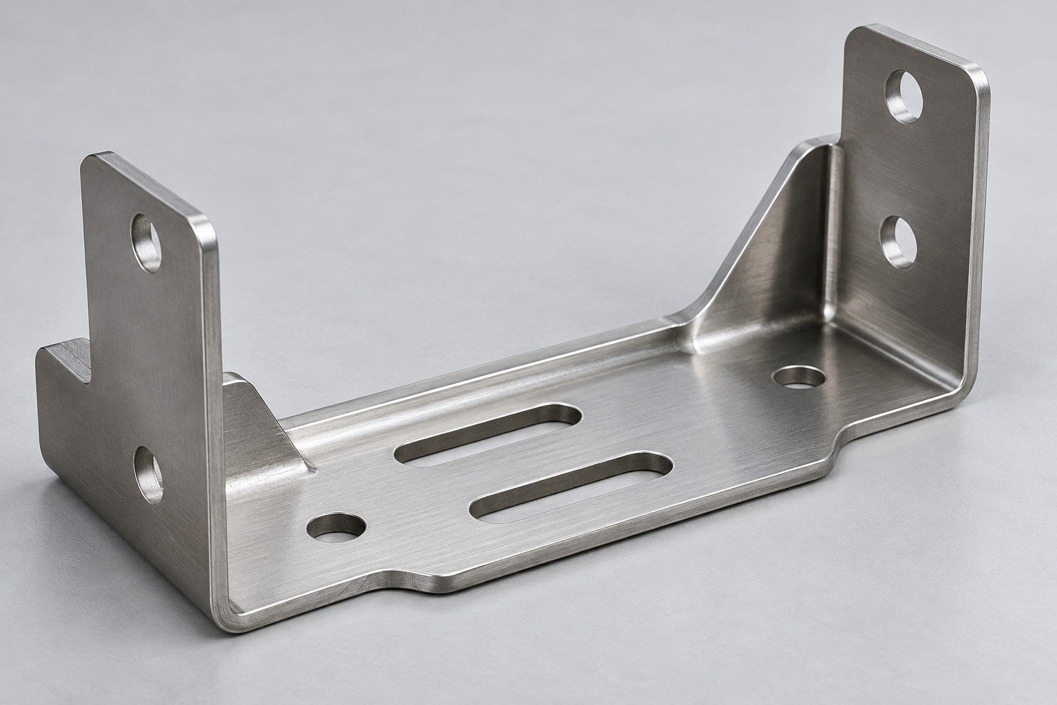
Cutting, forming and welding for your fabricated parts.
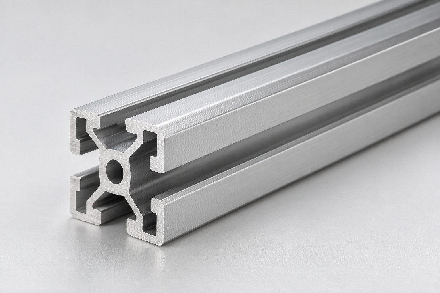
Custom profiles for your section, length and finish requirements.
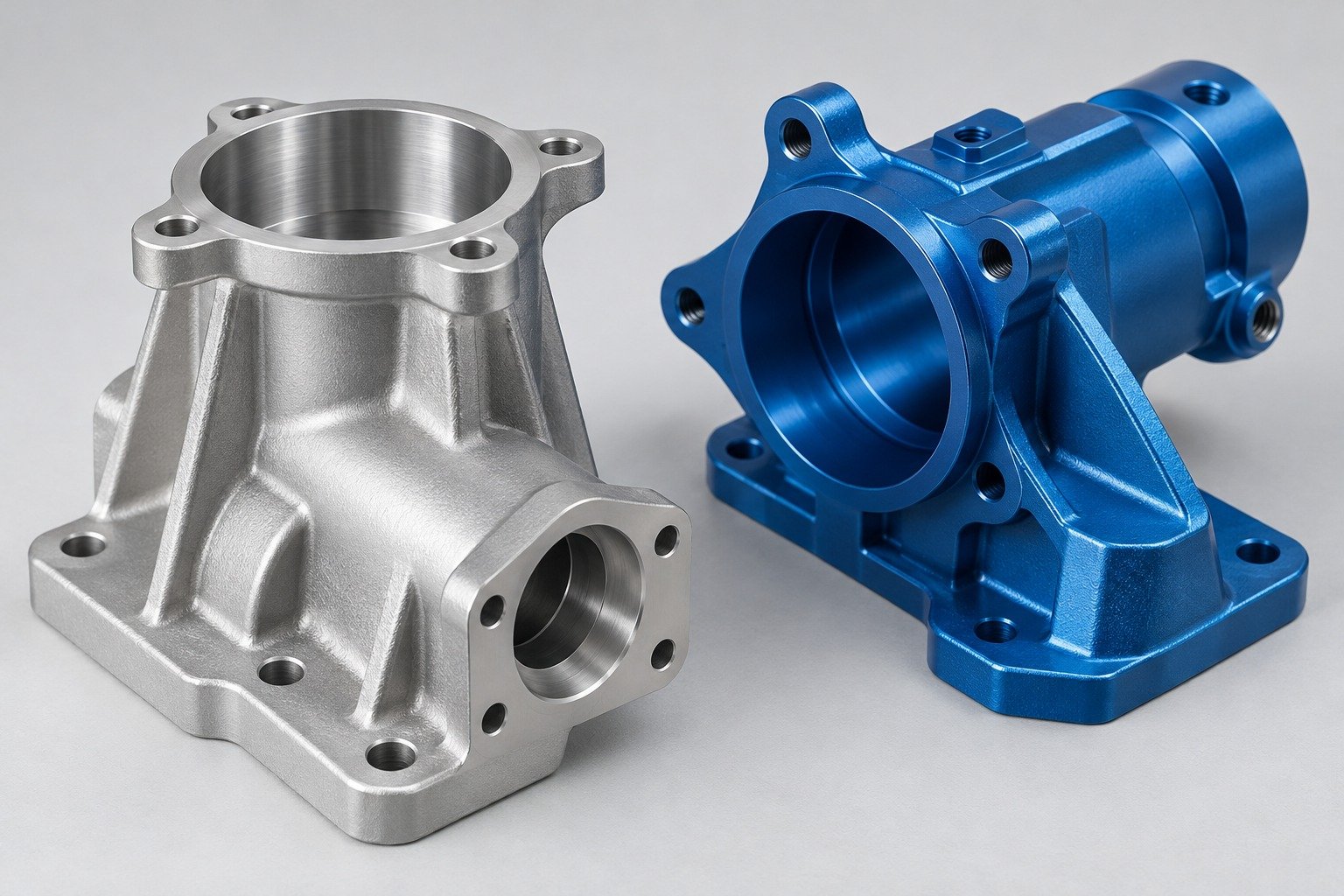
Finishes for your appearance, corrosion and wear requirements.
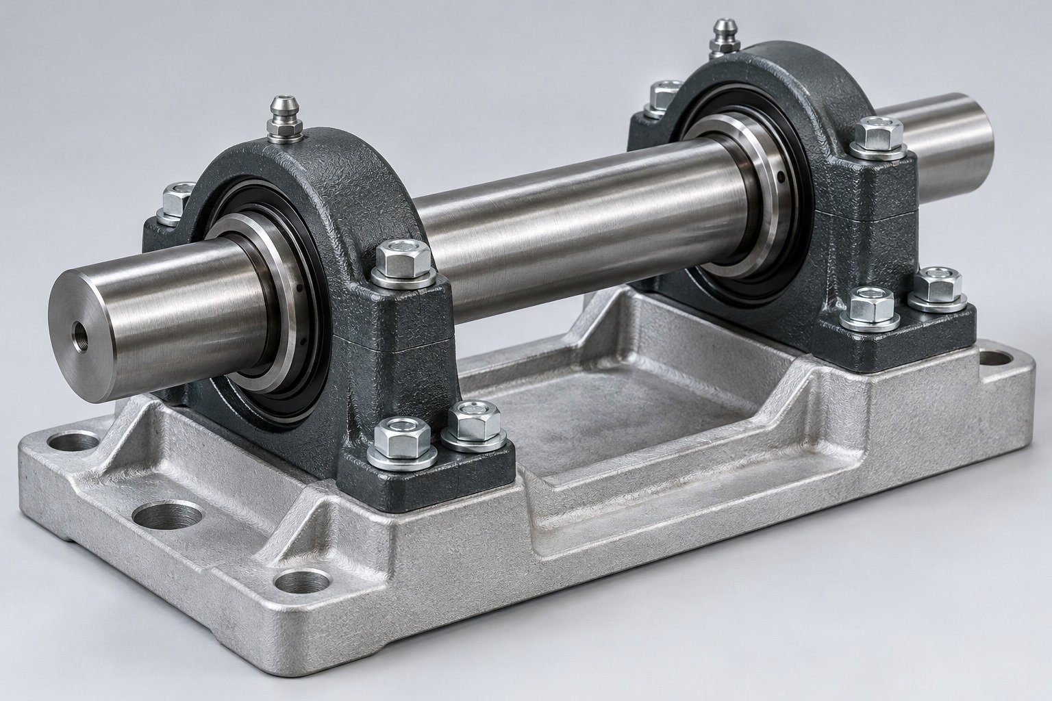
Sub-assemblies and final builds for your production program.
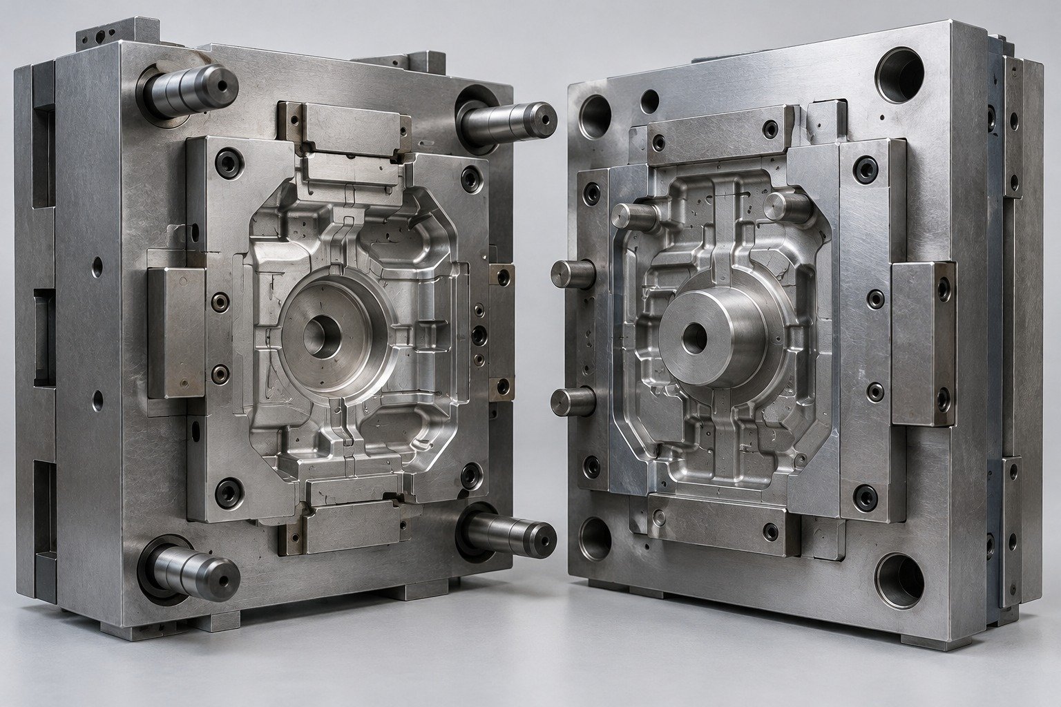
Production tooling built around your process and volume.
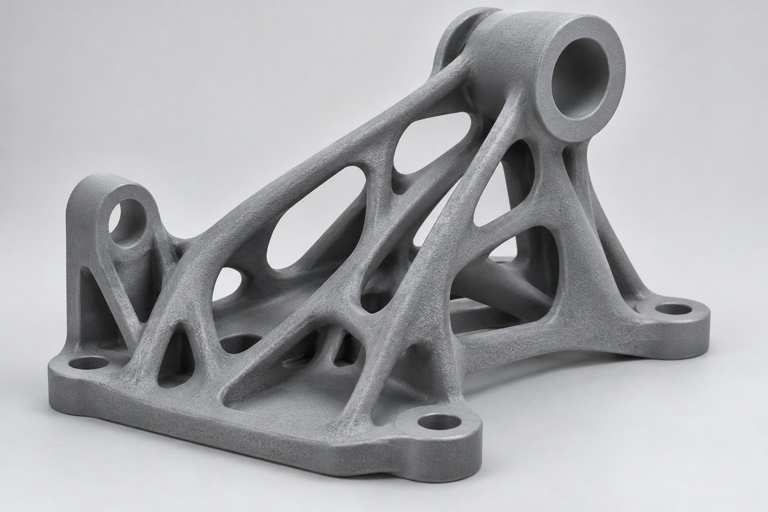
Prototype parts to check fit, function and design.
Choose air- or liquid-cooling components around your thermal and mechanical requirements.
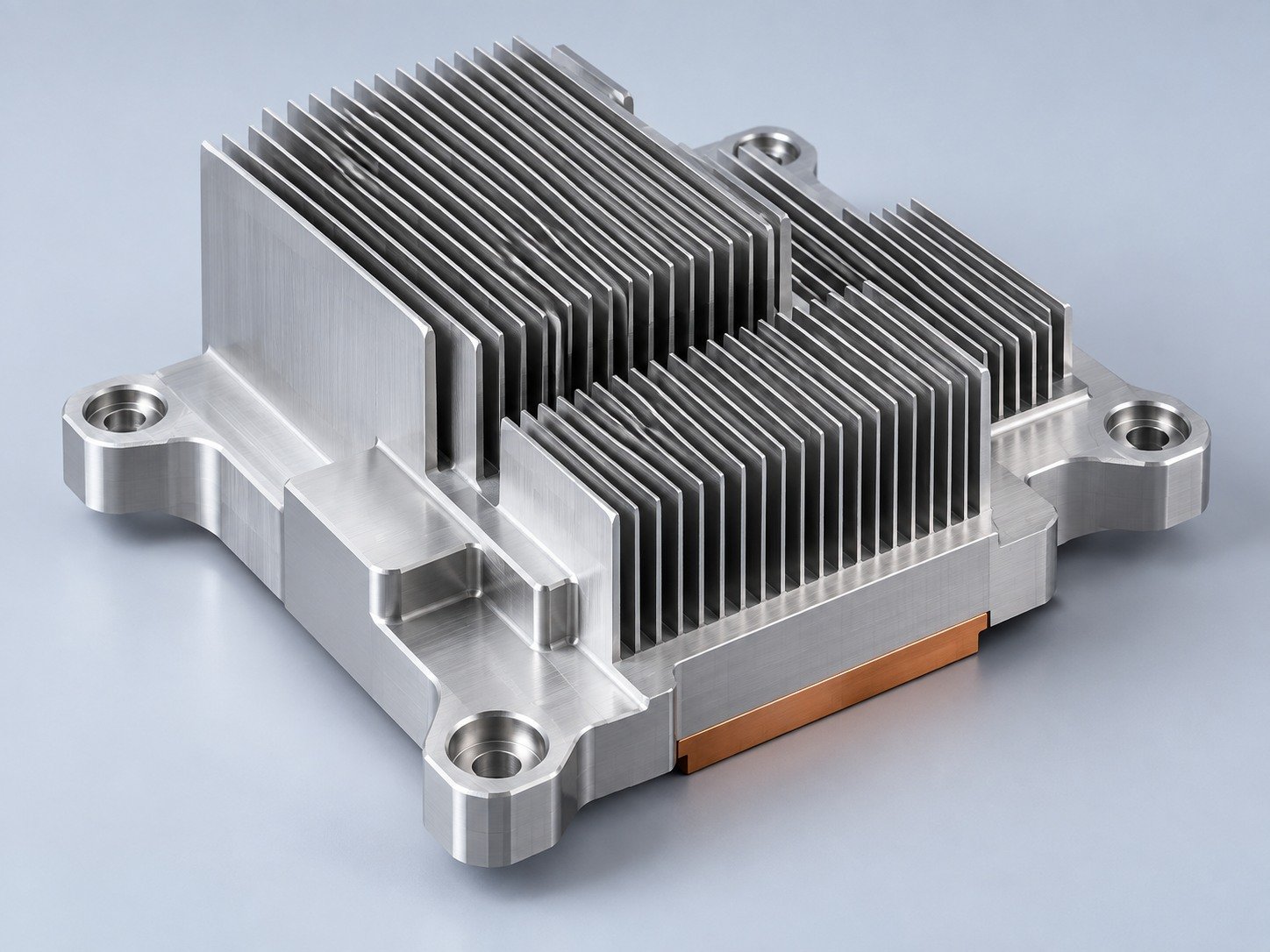
Manufacturing support for your cold plates, manifolds and cooling assemblies.
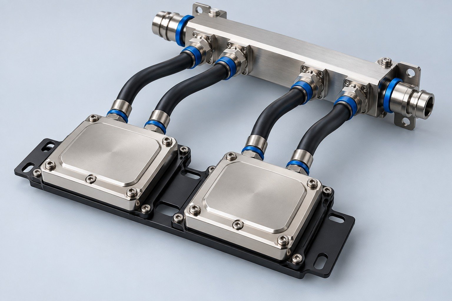
Find components for your power electronics, energy, laser and telecom application.
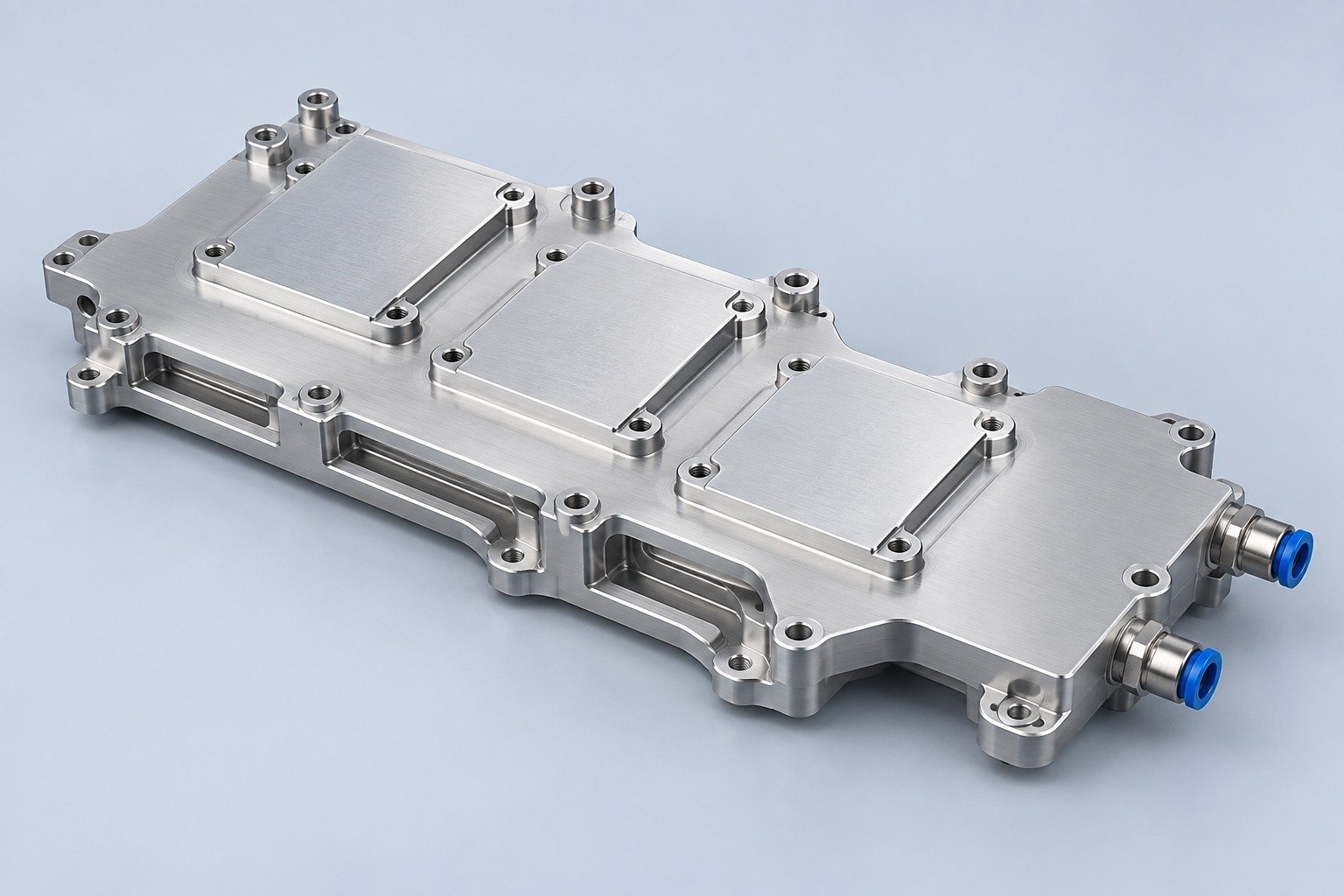
Components for your electronic systems.
Start with your functional and quality requirements.
Build around your operating environment.
From prototype to production, review material performance, manufacturability and cost for your part.
Review grade, temper and finish for your metal parts.
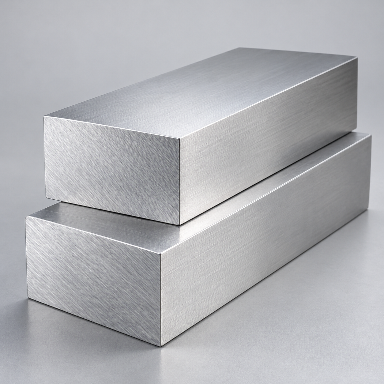 AluminumStrength, weight and machining›
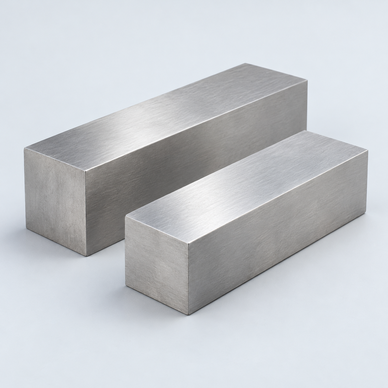 Stainless SteelCorrosion and finish requirements›
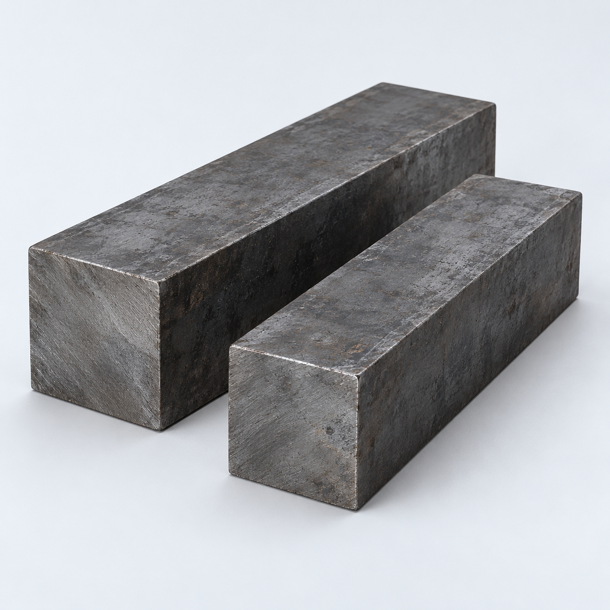 Carbon & Alloy SteelDiscuss grade and heat treatment›
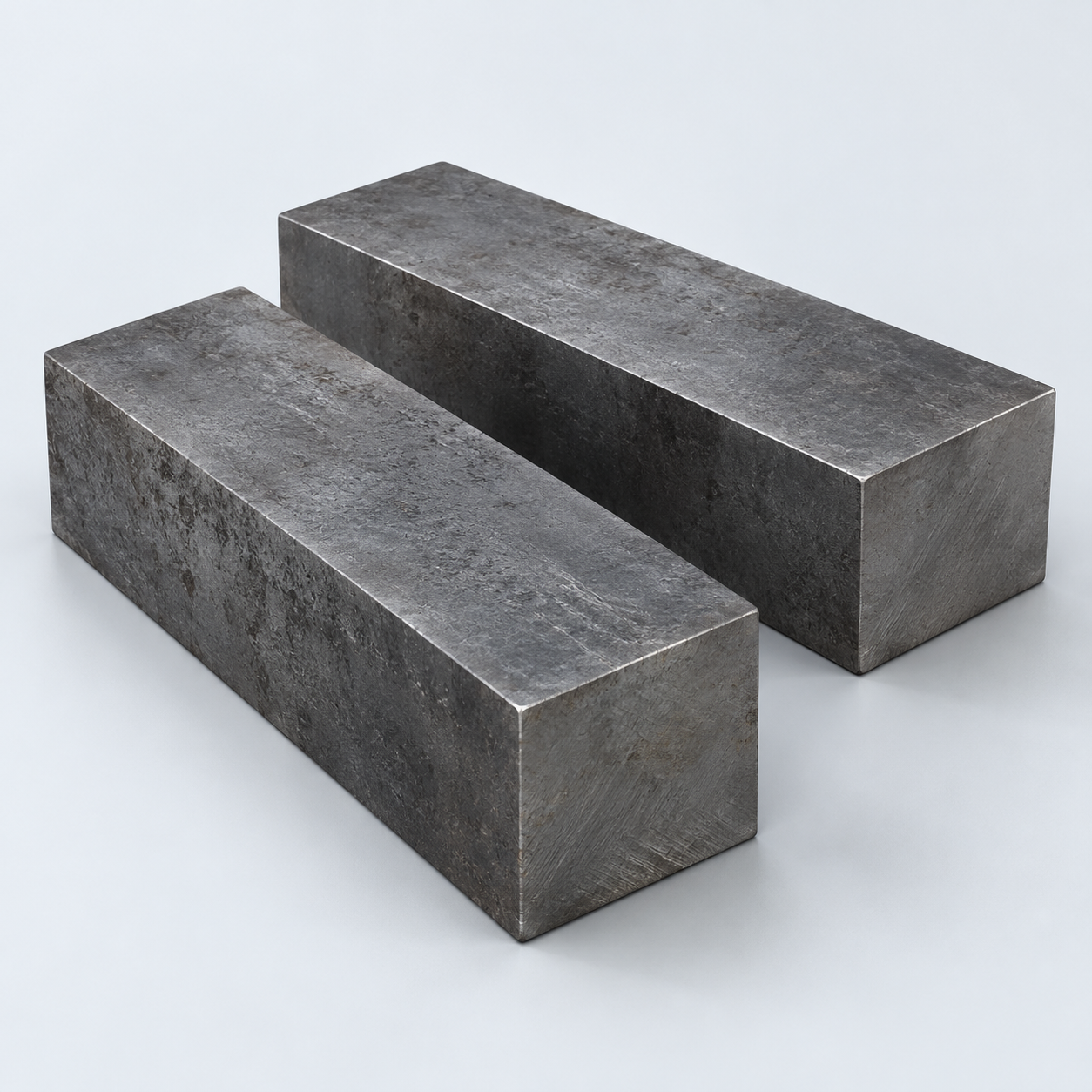 Tool SteelDiscuss tooling and wear needs›
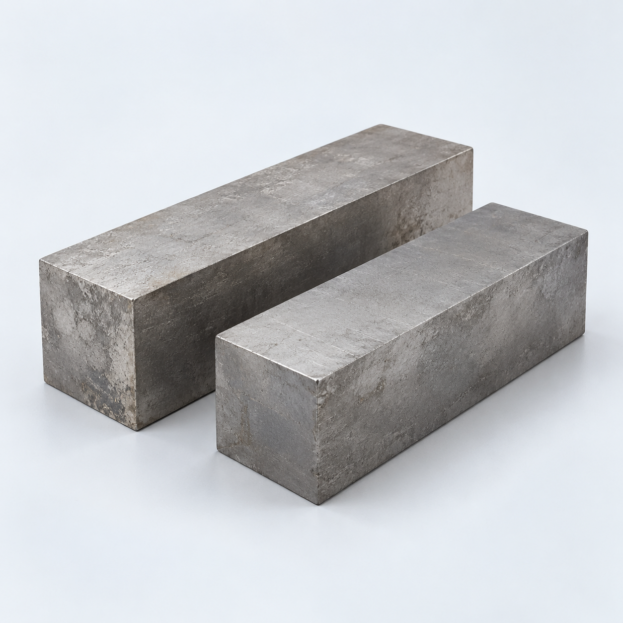 TitaniumReview grade and part geometry›
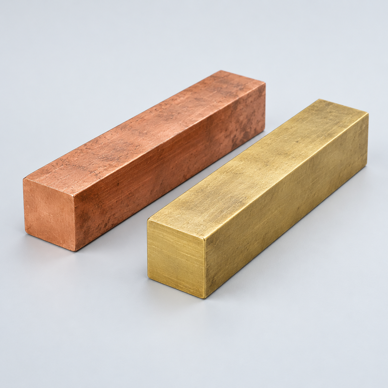 Copper & BrassDiscuss conductivity and machining›
Match your polymer to function, process and environment.
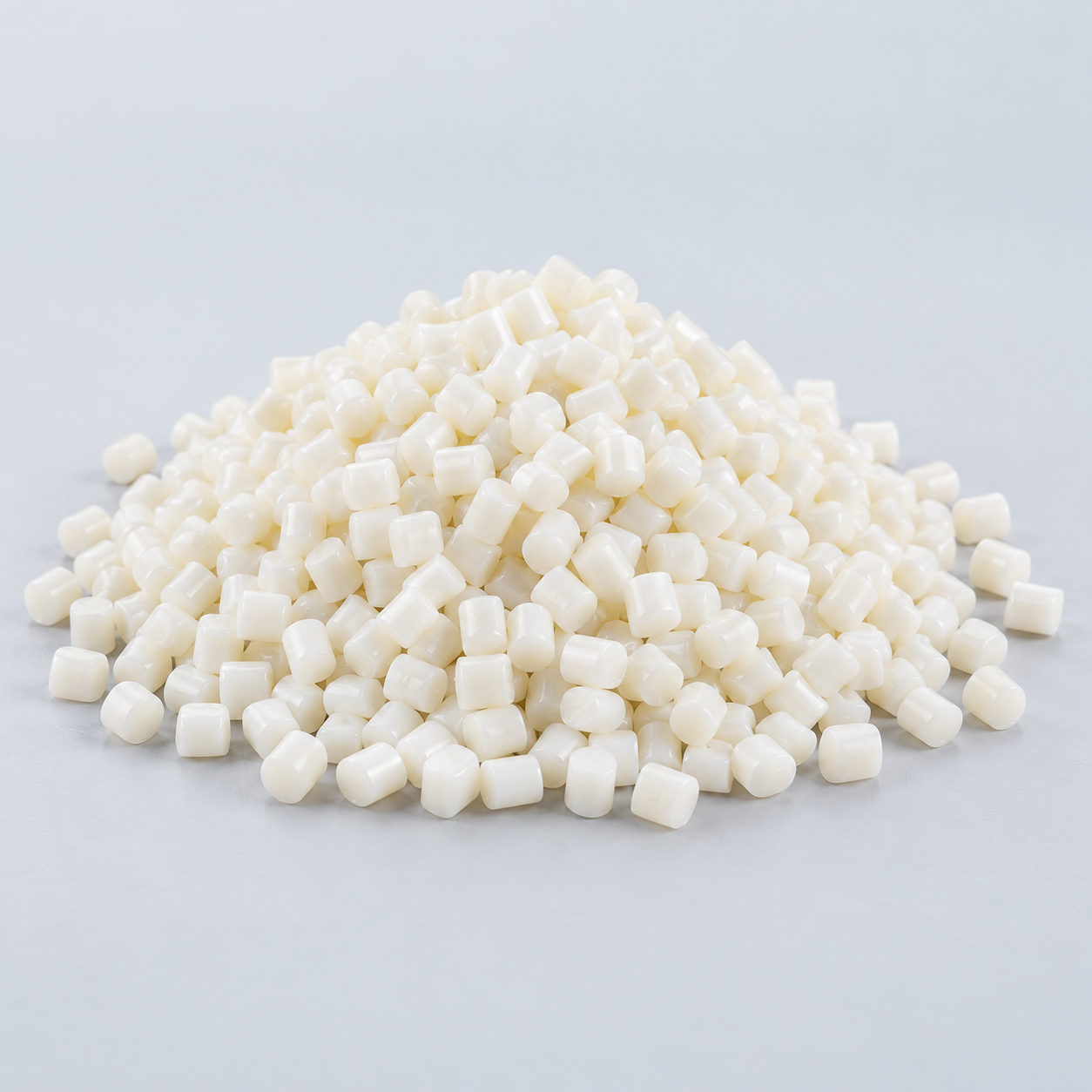 ABSReview enclosure and molding needs›
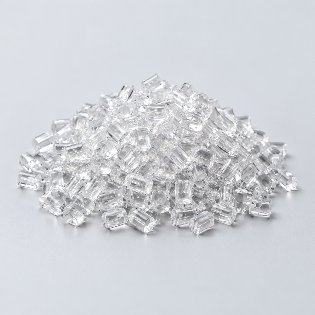 Polycarbonate (PC)Discuss clarity and impact needs›
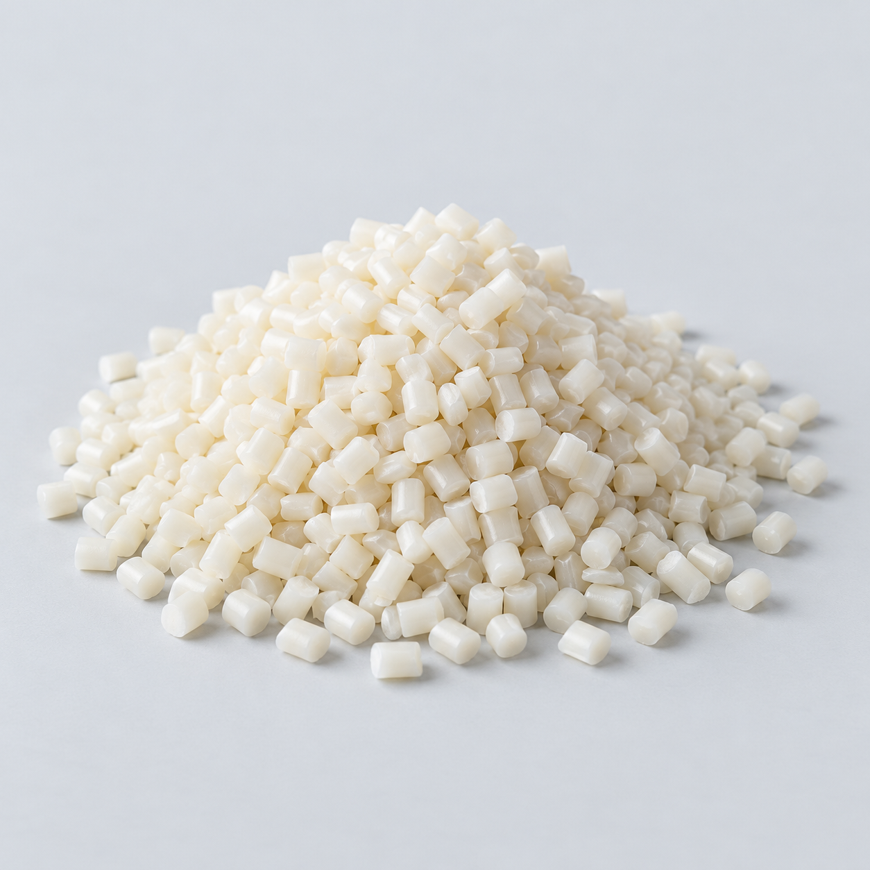 Nylon (PA)Review moisture and wear conditions›
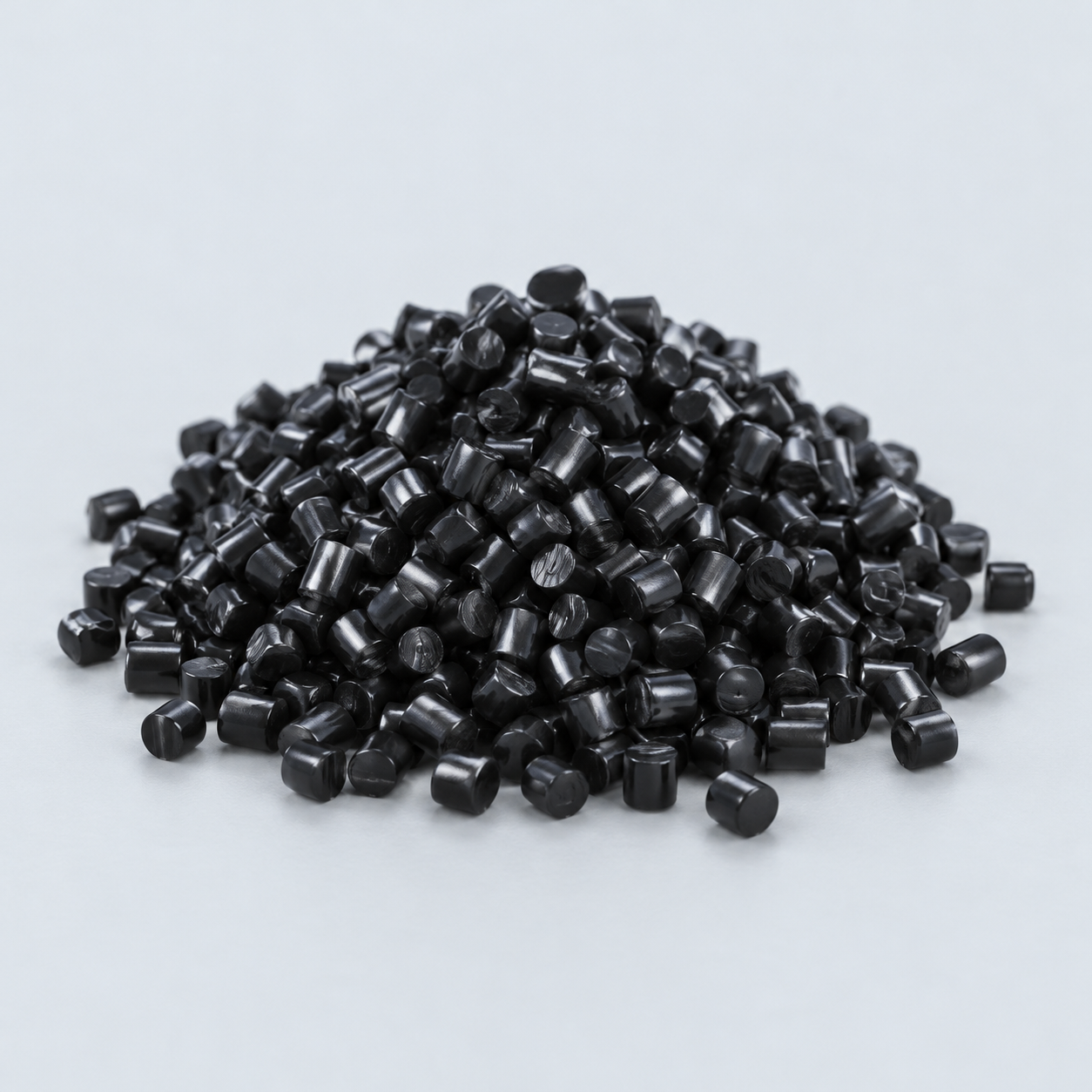 POM / AcetalReview fit and sliding features›
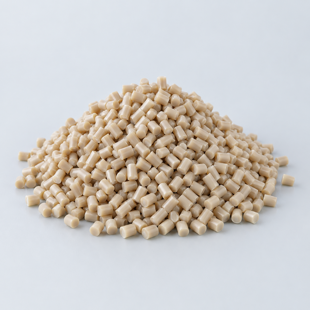 PEEKDiscuss operating conditions›
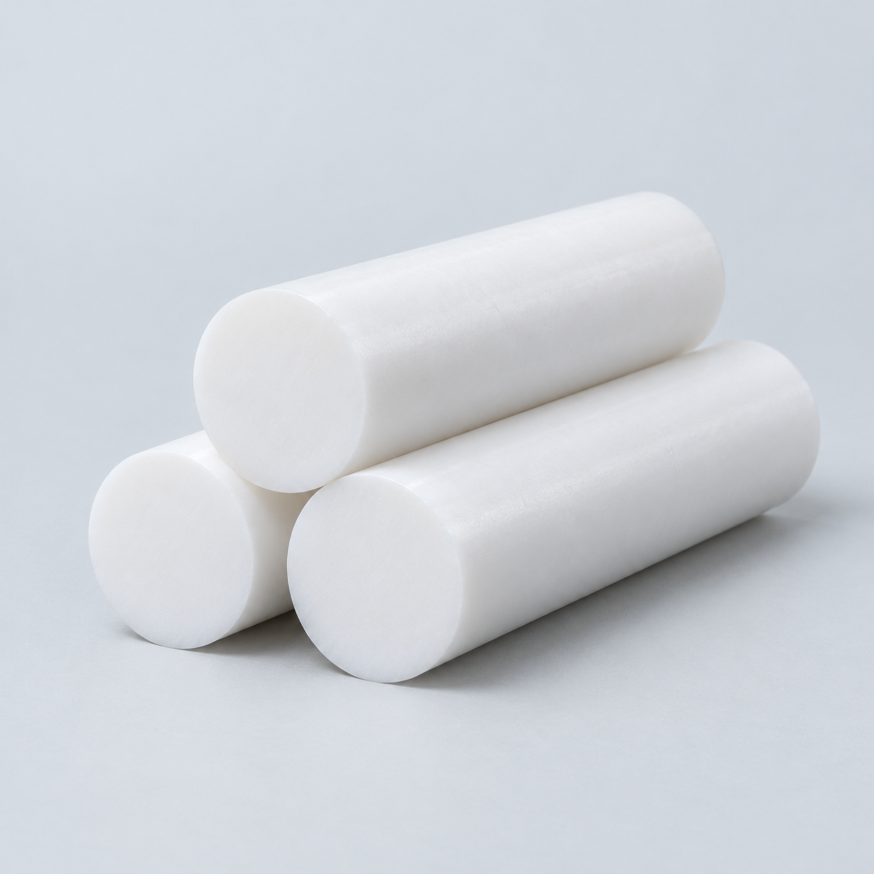 PTFEReview friction and chemical exposure›
 ULTEM / PEIDiscuss thermal and electrical needs›
Confirm grade availability and application requirements.
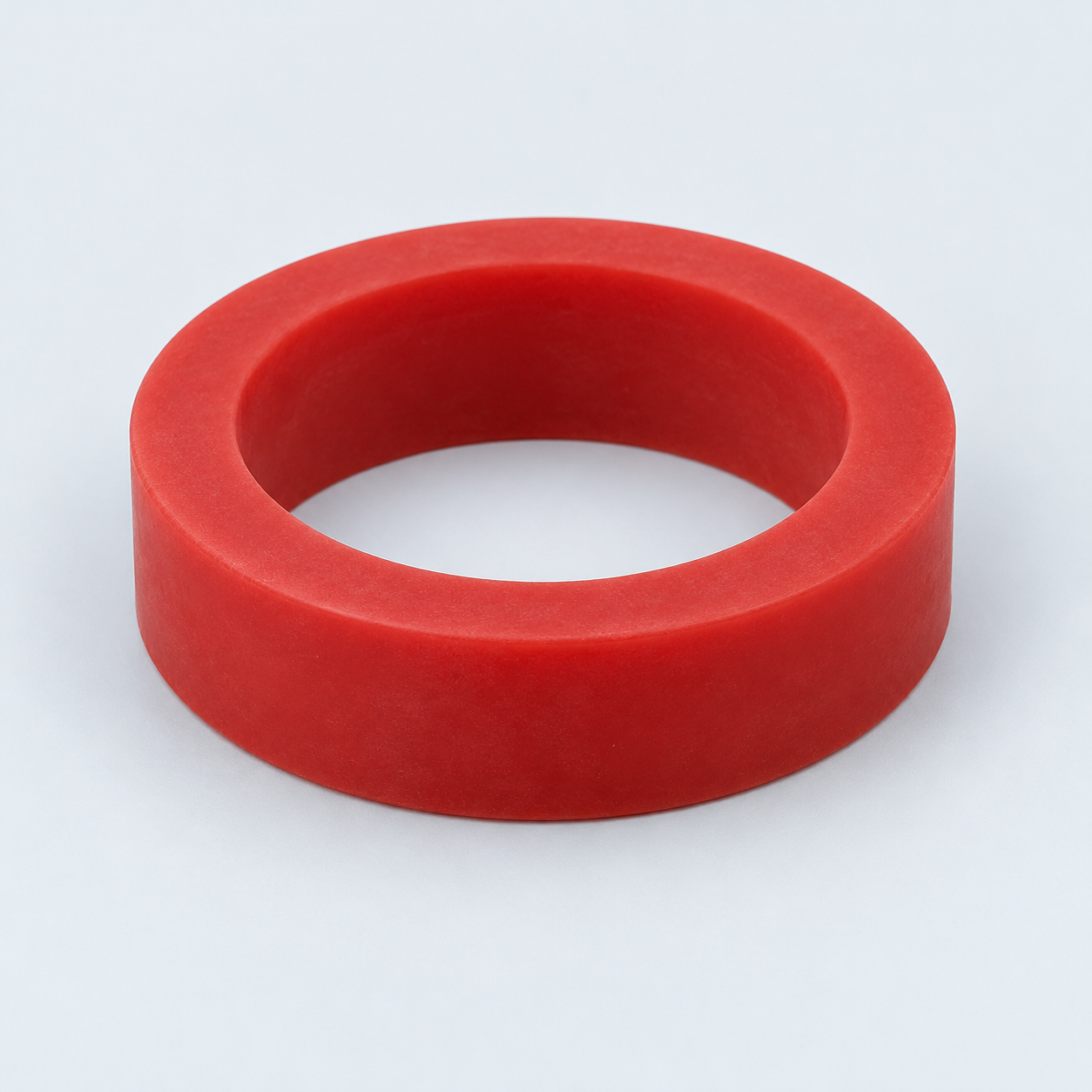 Silicone / LSRDiscuss flexible component needs›
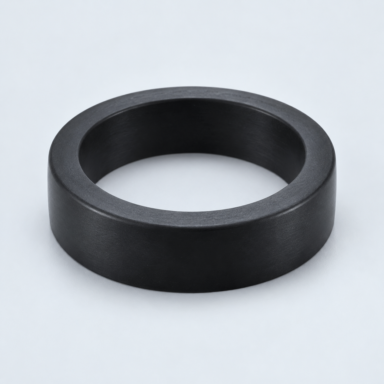 TPU / TPEReview flexibility and processing›
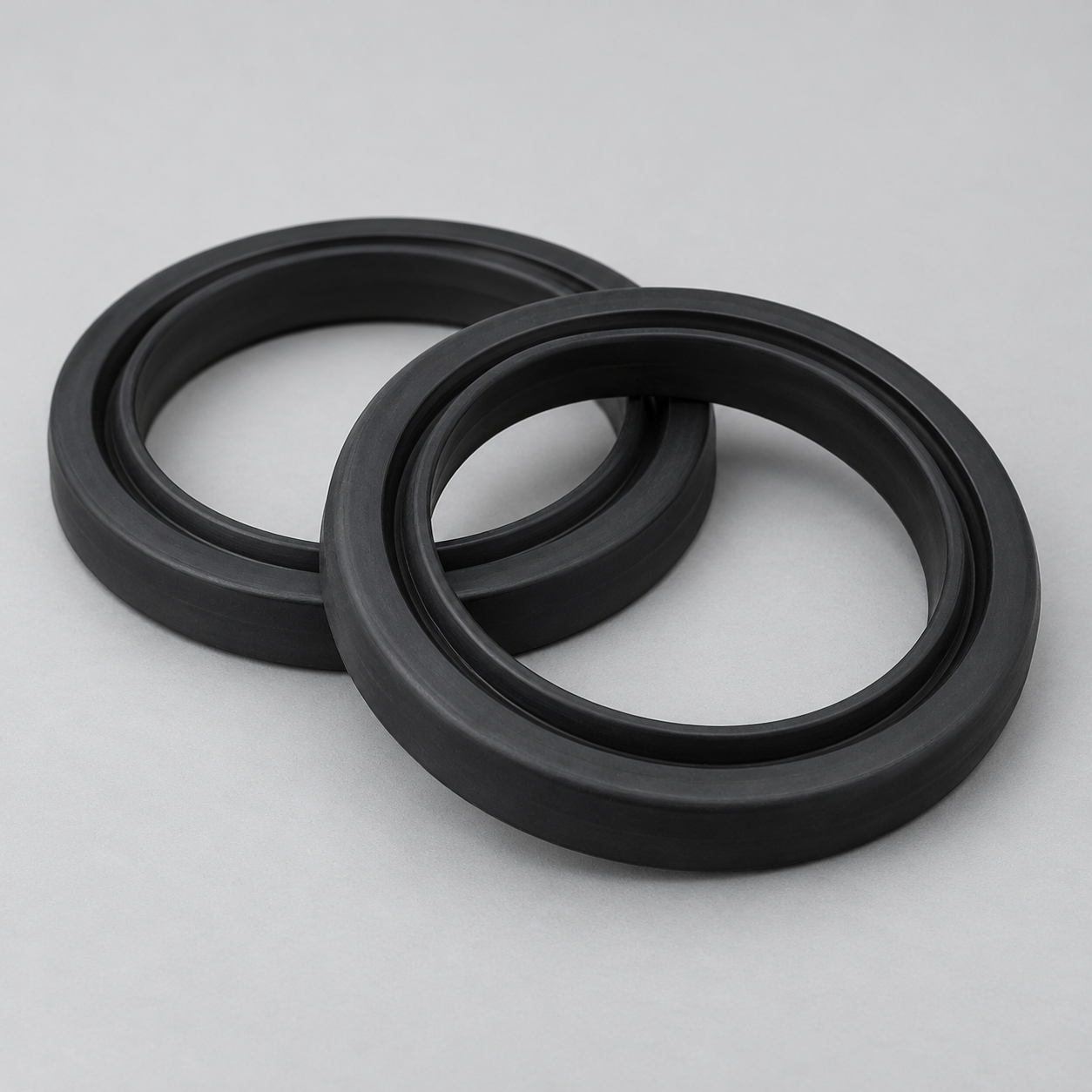 EPDMReview weathering and chemical exposure.›
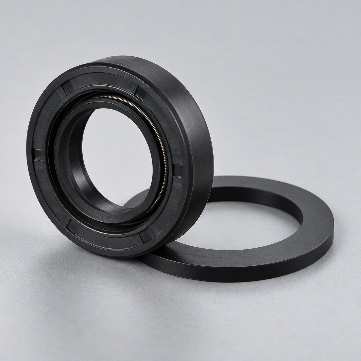 NBRReview oil and fuel exposure.›
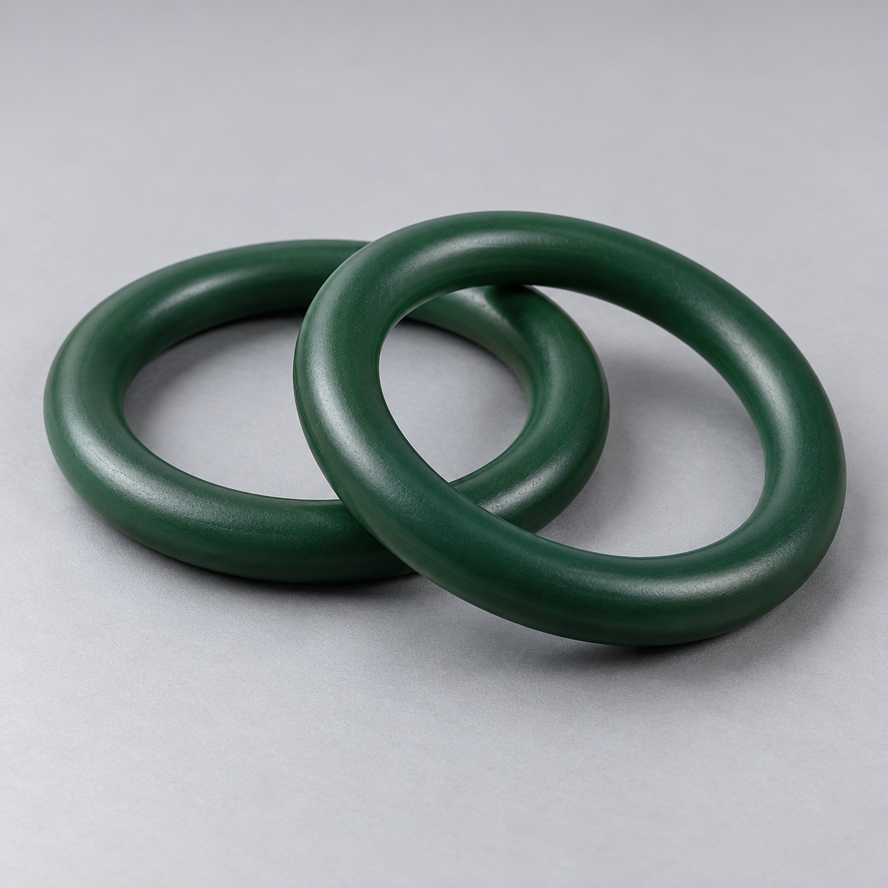 FKMReview temperature and chemical exposure.›
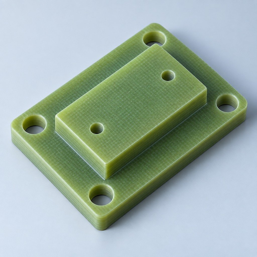 G10 / FR4Review insulation and laminate needs›
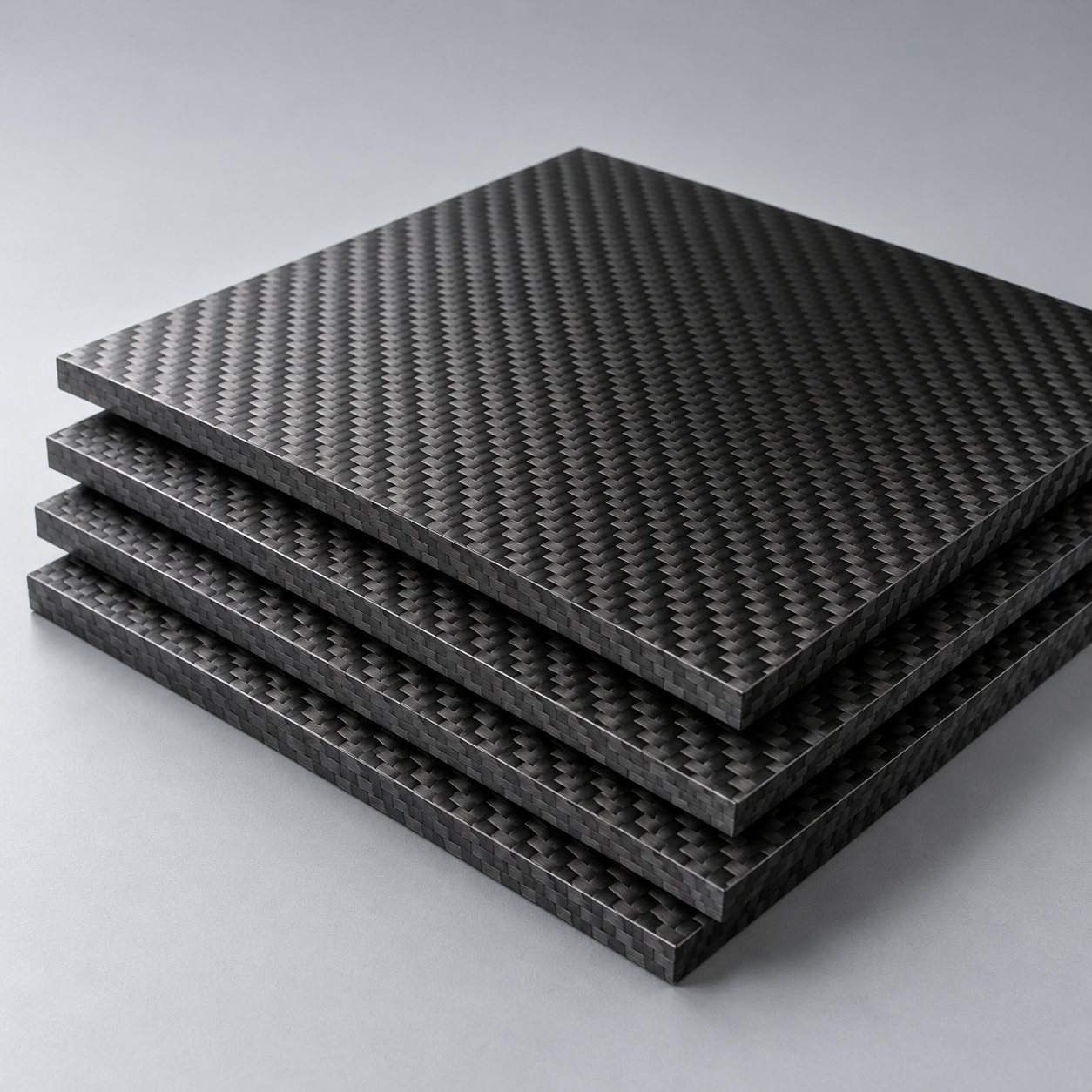 CompositesReview stiffness, weight and laminate.›Customer-Specified MaterialsConfirm your grade and requirements.›Other Specialty MaterialsDiscuss your application and grade.›
Practical guidance for your part geometry and material decisions.
Prepare your process, budget and sourcing questions.
Build your knowledge before production.
Learn who we are and how we operate.
Find our U.S. support team or start a conversation.
YOUR DRAWING. YOUR MATERIAL. YOUR ACCEPTANCE PLAN.
Plan your steel or iron casting around internal passages, machining stock and acceptance criteria. Review the pattern, core plan and final drawing before committing to production.
Start with CAD model + controlled 2D drawing.
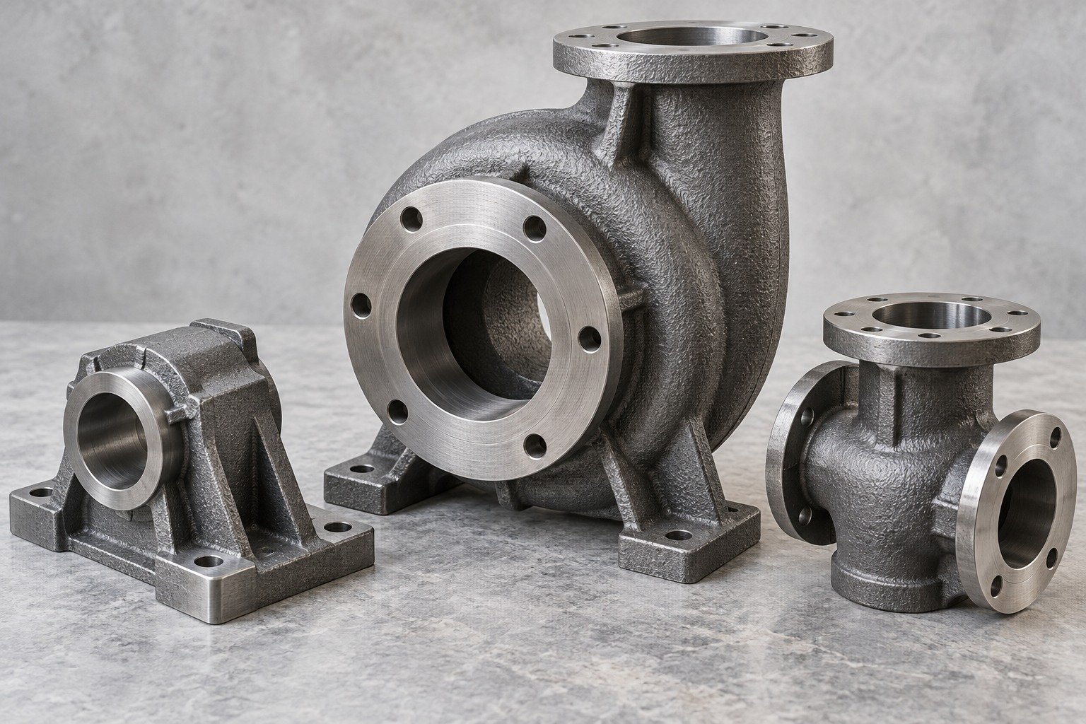
Casting grade and delivery condition.
Geometry and reusable tooling.
For your final fit.
Trial castings and validation.
Dallas-area project support.
Define the requirements that affect your material, tooling and acceptance plan.
Casting grade, condition and service environment.
Cored passages, machining datums and final fit.
Trial quantity, first order and repeat demand.
Sand casting forms metal in an expendable sand mold. Cores can create internal passages.
Mark bearing bores, sealing faces and assembly datums; keep the as-cast envelope separate from final machined features.
| For your function | Environment, mating parts and enclosure needs |
|---|---|
| For your fit | Datums, bores and machined sealing faces |
| For your approval | Surface zones and acceptance records |
Application concepts; geometry, grade and manufacturing scope are reviewed for your project.
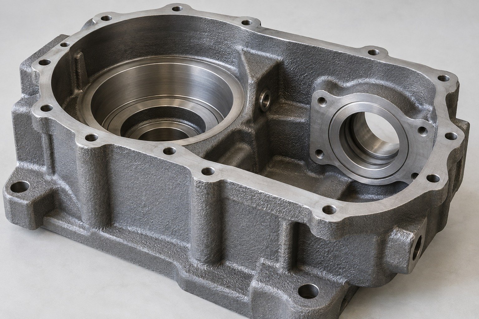
Match your sand casting materials to loads, temperature and required properties. Grade, availability, delivery condition and test scope are confirmed for your drawing.
| Your grade | Casting specification and delivery condition |
|---|---|
| Your use | Loads, temperature, fluids and exposure |
| Your records | Material lot and required property tests |
Application concepts; geometry, grade and manufacturing scope are reviewed for your project.
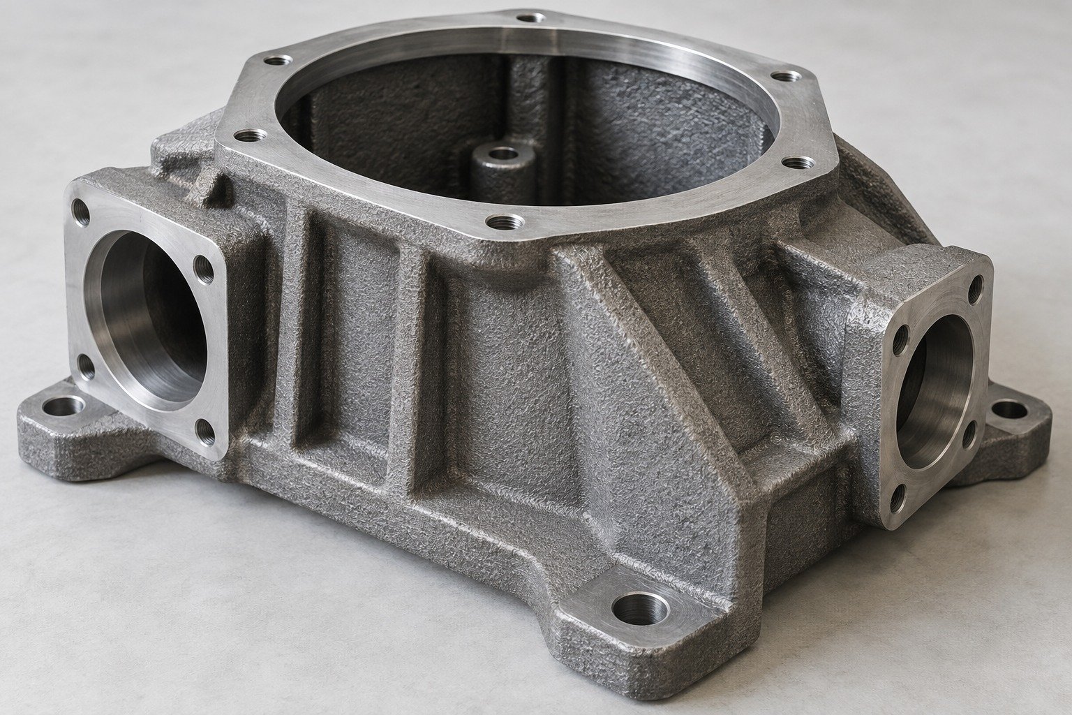
Sand casting pattern design must allow for shrinkage, release and specified machining stock. Confirm the mold and core system for your grade and geometry.
| Your pattern | Parting, draft and shrinkage compensation |
|---|---|
| Your cores | Core prints, support and removal access |
| Your final fit | Datums, stock and fixture access |
Application concepts; geometry, grade and manufacturing scope are reviewed for your project.
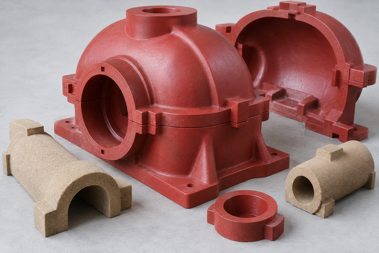
Use trial castings to confirm the agreed material, cored geometry and finished features. A CNC-only mockup does not validate as-cast quality.
| Your material | Grade, condition and traceability |
|---|---|
| Your casting | Core position, surfaces and specified tests |
| Your final fit | Machined dimensions and datum scheme |
Application concepts; geometry, grade and manufacturing scope are reviewed for your project.
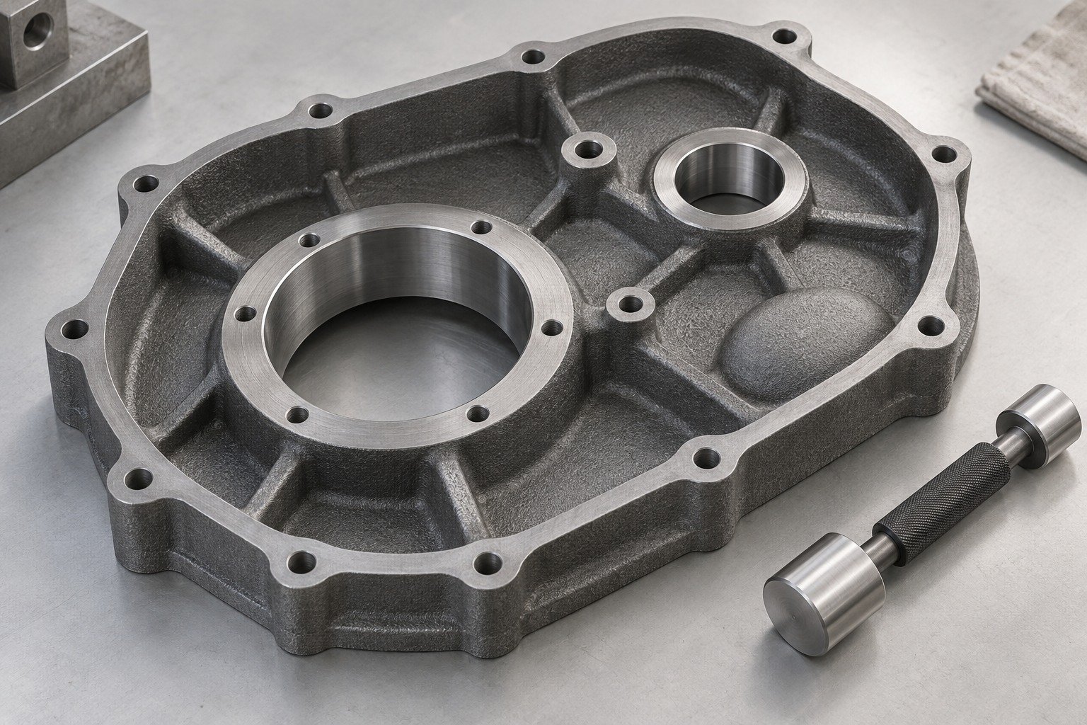
For sand casting for pumps and valves, identify flow passages, clean-out access and specified pressure or leak checks.
| For your flow | Passage geometry and clean-out access |
|---|---|
| For your fit | Core position, wall sections and machining datums |
| For your approval | Surface zones, records and specified tests |
Application concepts; geometry, grade and manufacturing scope are reviewed for your project.
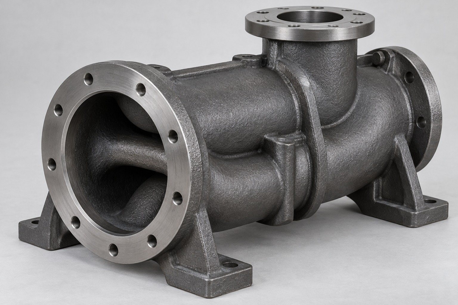
Match your sand casting materials to loads, temperature and required properties. Grade, availability, delivery condition and test scope are confirmed for your drawing.
| Your grade | Casting specification and delivery condition |
|---|---|
| Your use | Loads, temperature, fluids and exposure |
| Your records | Material lot and required property tests |
Application concepts; geometry, grade and manufacturing scope are reviewed for your project.
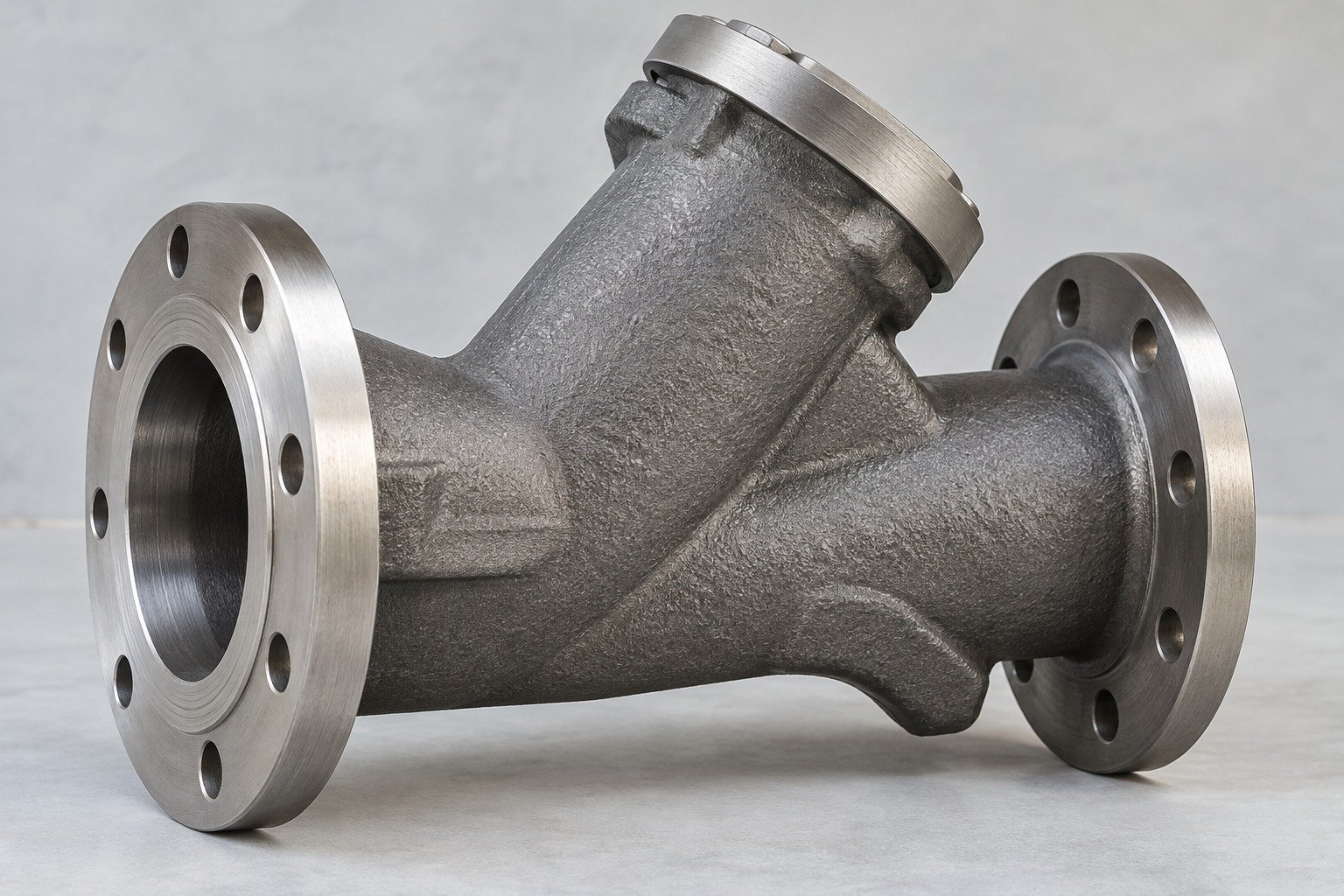
Sand casting pattern design must allow for shrinkage, release and specified machining stock. Confirm the mold and core system for your grade and geometry.
| Your pattern | Parting, draft and shrinkage compensation |
|---|---|
| Your cores | Core prints, support and removal access |
| Your final fit | Datums, stock and fixture access |
Application concepts; geometry, grade and manufacturing scope are reviewed for your project.
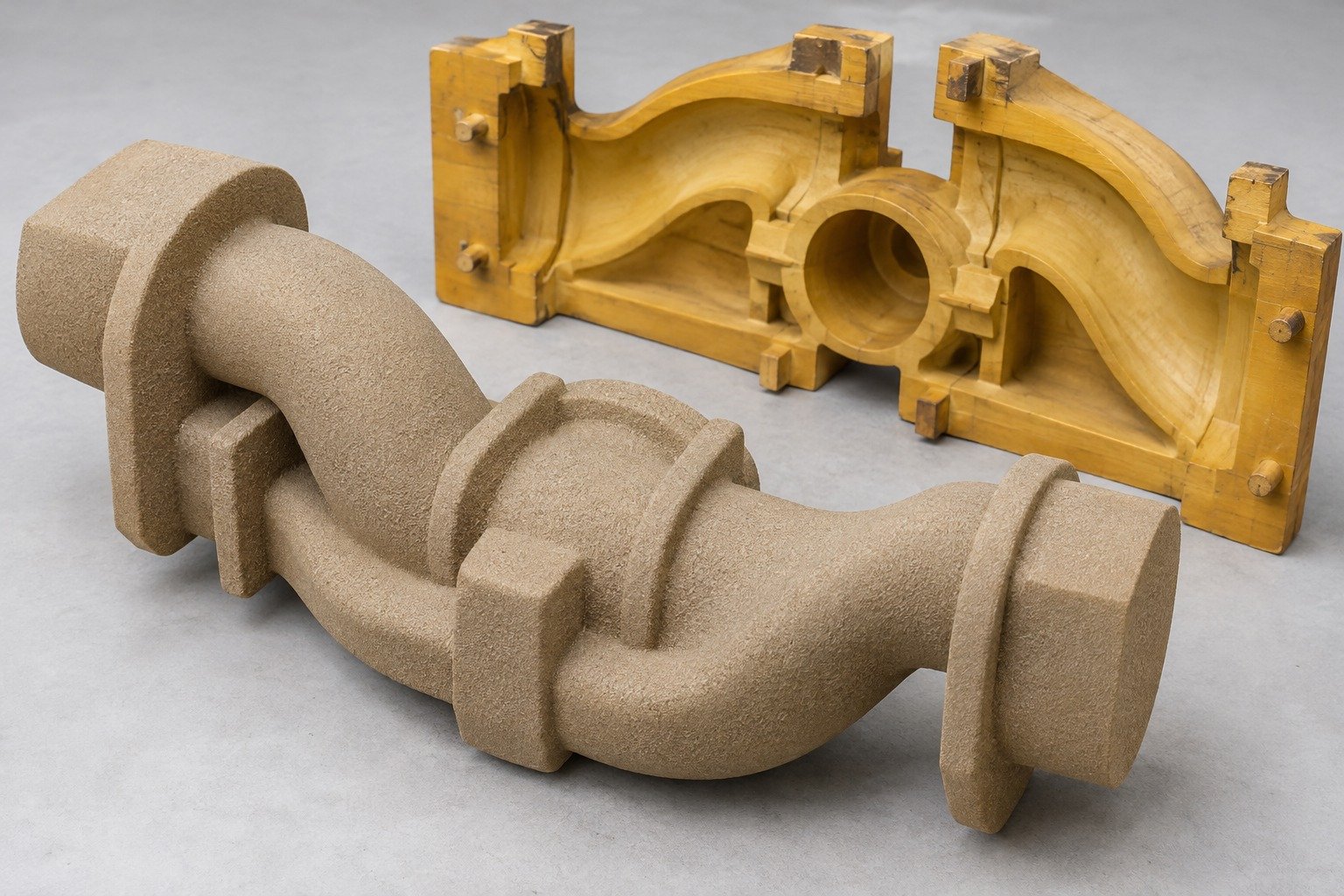
Use trial castings to confirm the agreed material, cored geometry and finished features. A CNC-only mockup does not validate as-cast quality.
| Your material | Grade, condition and traceability |
|---|---|
| Your casting | Core position, surfaces and specified tests |
| Your final fit | Machined dimensions and datum scheme |
Application concepts; geometry, grade and manufacturing scope are reviewed for your project.
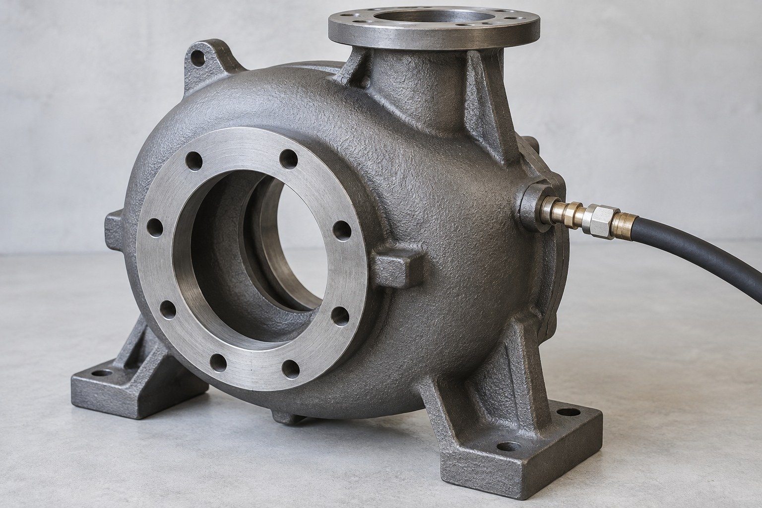
Define mounting pads, load direction, fillets and the machined faces that locate your assembly.
| For your loads | Direction, mounting and working conditions |
|---|---|
| For your fit | Machined pads, fasteners and locating features |
| For your approval | Drawing limits and specified load checks |
Application concepts; geometry, grade and manufacturing scope are reviewed for your project.
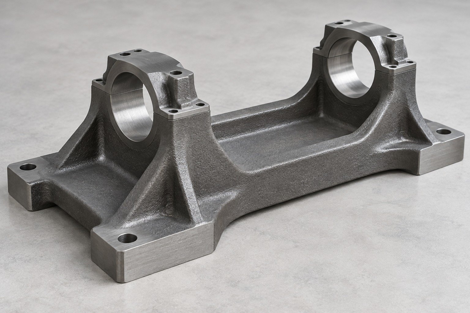
Match your sand casting materials to loads, temperature and required properties. Grade, availability, delivery condition and test scope are confirmed for your drawing.
| Your grade | Casting specification and delivery condition |
|---|---|
| Your use | Loads, temperature, fluids and exposure |
| Your records | Material lot and required property tests |
Application concepts; geometry, grade and manufacturing scope are reviewed for your project.
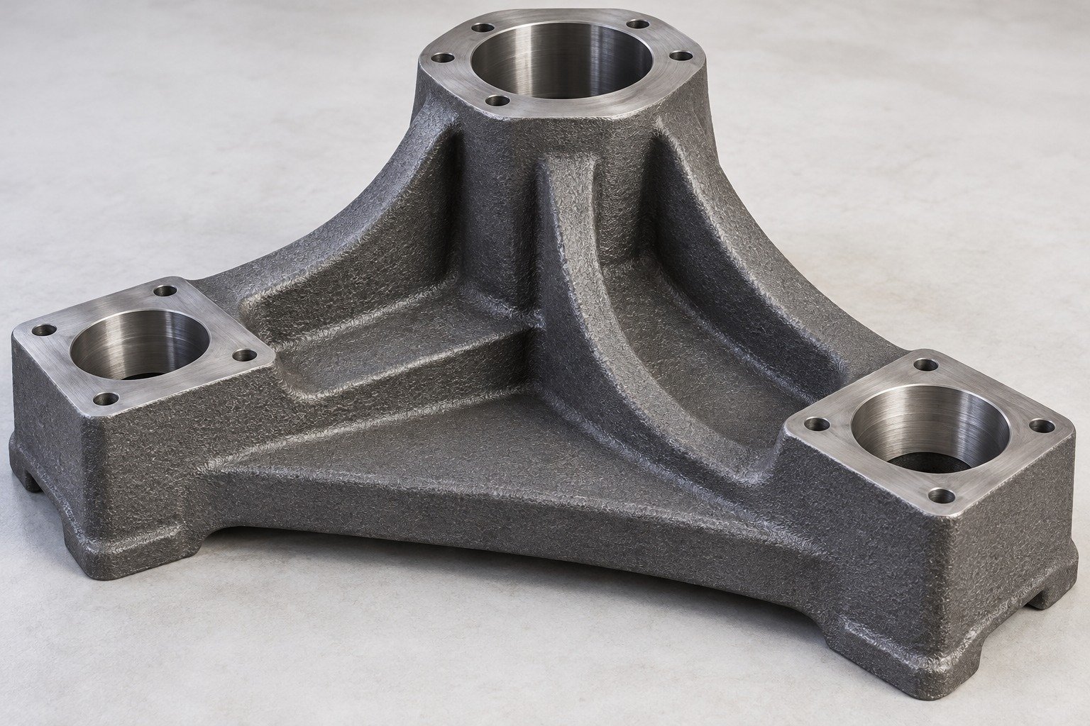
Sand casting pattern design must allow for shrinkage, release and specified machining stock. Confirm the mold and core system for your grade and geometry.
| Your pattern | Parting, draft and shrinkage compensation |
|---|---|
| Your cores | Core prints, support and removal access |
| Your final fit | Datums, stock and fixture access |
Application concepts; geometry, grade and manufacturing scope are reviewed for your project.
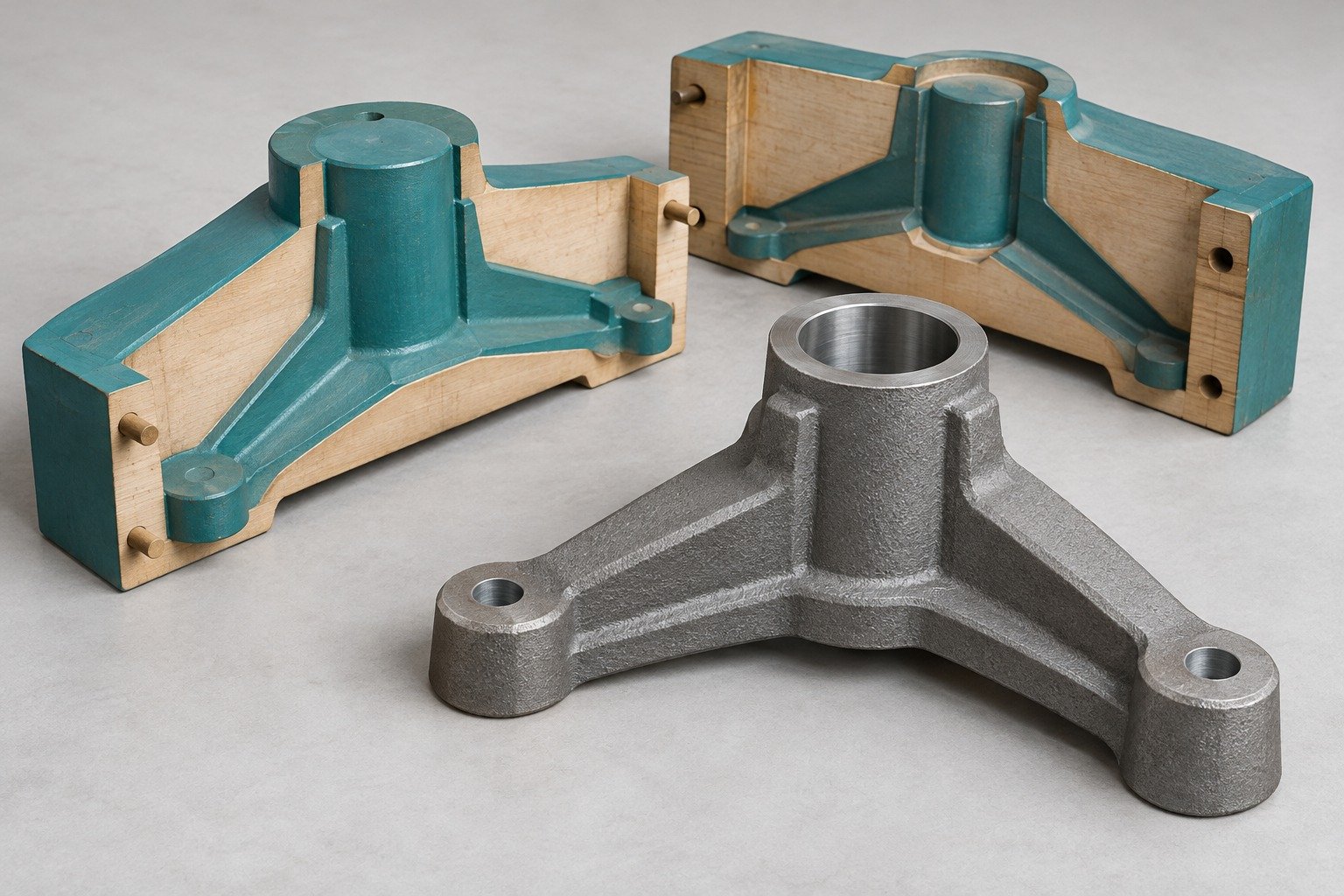
Use trial castings to confirm the agreed material, cored geometry and finished features. A CNC-only mockup does not validate as-cast quality.
| Your material | Grade, condition and traceability |
|---|---|
| Your casting | Core position, surfaces and specified tests |
| Your final fit | Machined dimensions and datum scheme |
Application concepts; geometry, grade and manufacturing scope are reviewed for your project.
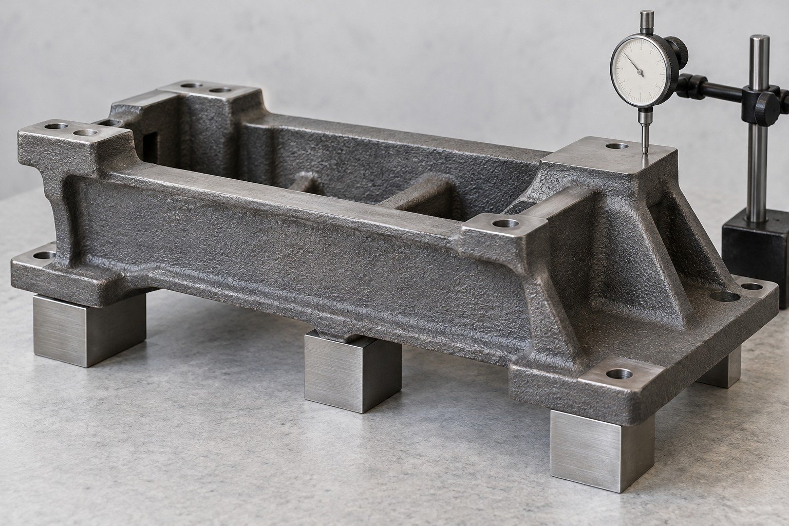
Share your drawing and use conditions so material, molding route, cores and secondary operations can be assessed together.
| For your function | Loads, environment and mating parts |
|---|---|
| For your fit | Cored geometry, datums and final dimensions |
| For your supply | Trial, first-order and annual demand |
Application concepts; geometry, grade and manufacturing scope are reviewed for your project.
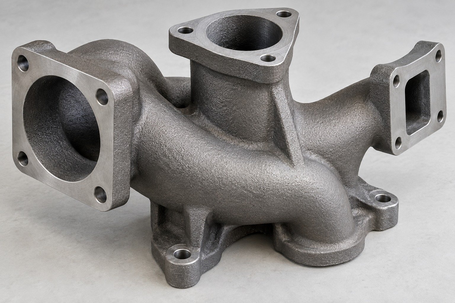
Match your sand casting materials to loads, temperature and required properties. Grade, availability, delivery condition and test scope are confirmed for your drawing.
| Your grade | Casting specification and delivery condition |
|---|---|
| Your use | Loads, temperature, fluids and exposure |
| Your records | Material lot and required property tests |
Application concepts; geometry, grade and manufacturing scope are reviewed for your project.
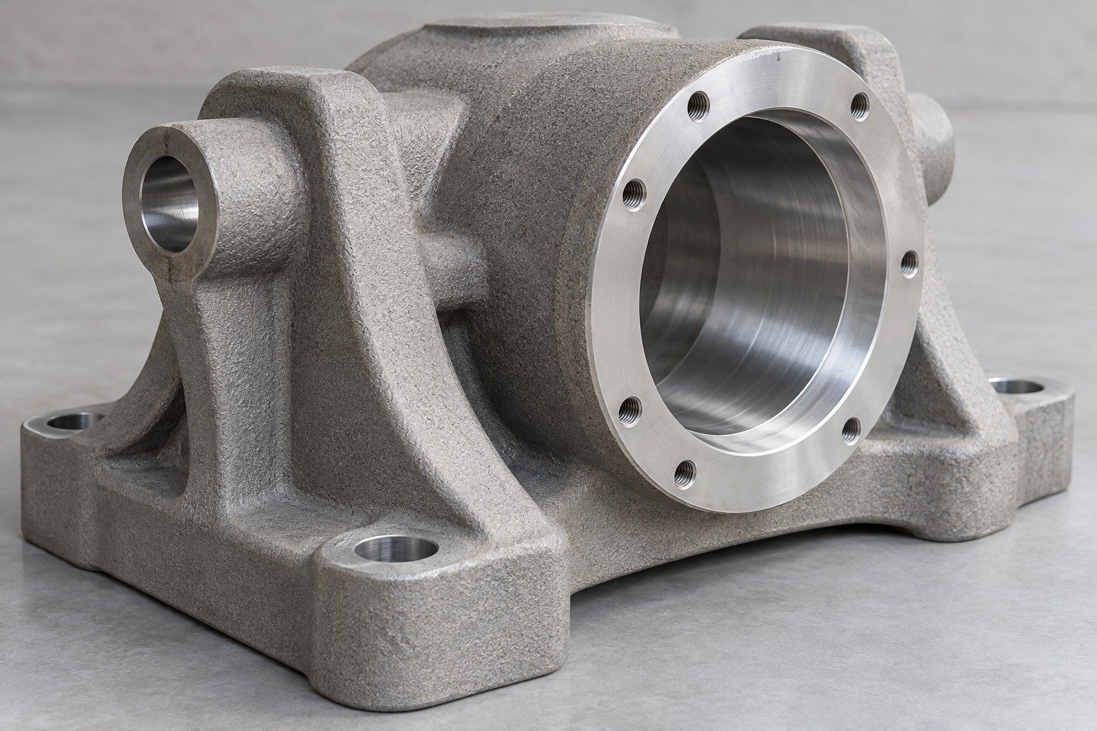
Sand casting pattern design must allow for shrinkage, release and specified machining stock. Confirm the mold and core system for your grade and geometry.
| Your pattern | Parting, draft and shrinkage compensation |
|---|---|
| Your cores | Core prints, support and removal access |
| Your final fit | Datums, stock and fixture access |
Application concepts; geometry, grade and manufacturing scope are reviewed for your project.
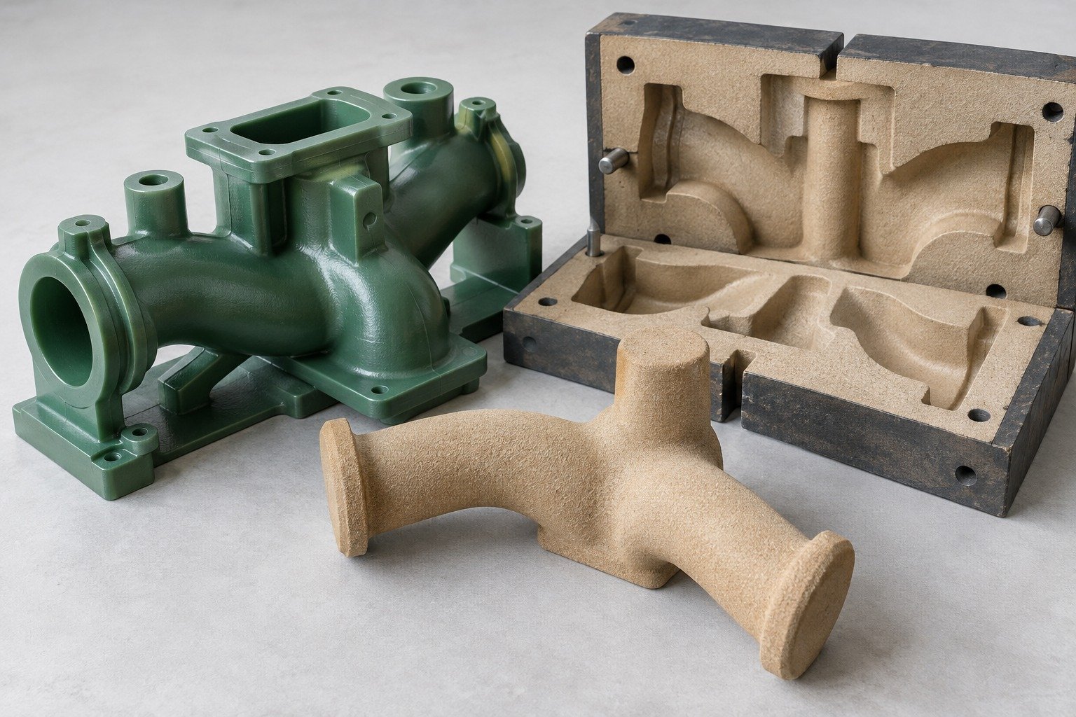
Use trial castings to confirm the agreed material, cored geometry and finished features. A CNC-only mockup does not validate as-cast quality.
| Your material | Grade, condition and traceability |
|---|---|
| Your casting | Core position, surfaces and specified tests |
| Your final fit | Machined dimensions and datum scheme |
Application concepts; geometry, grade and manufacturing scope are reviewed for your project.
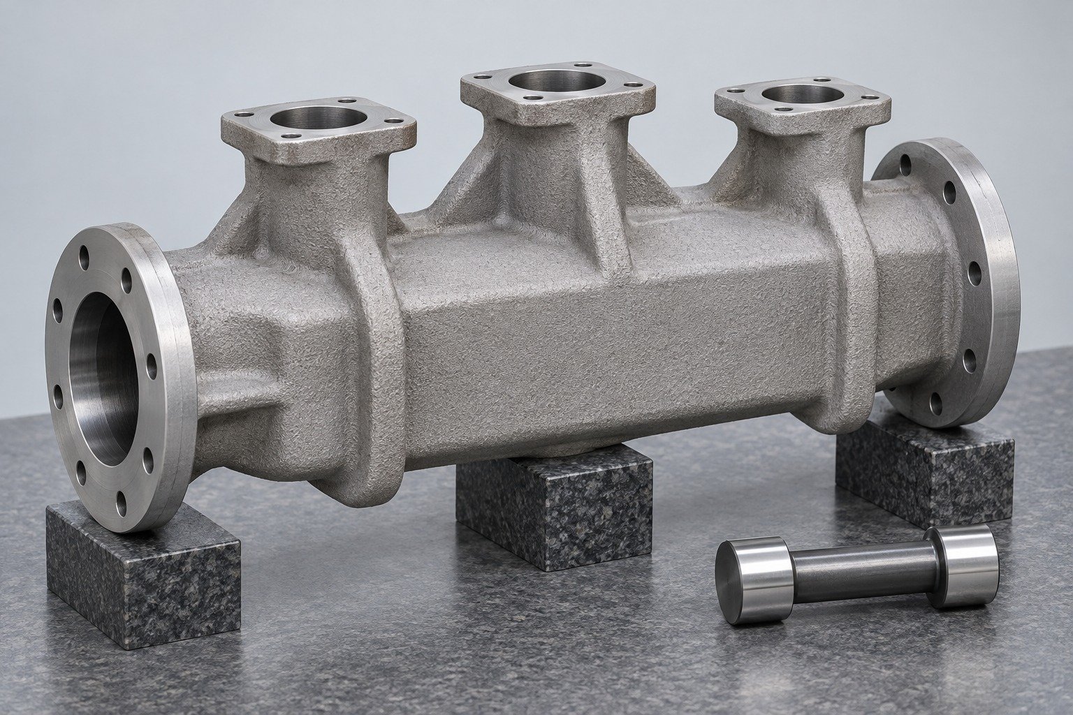
Select the material for your application, environment and performance needs.
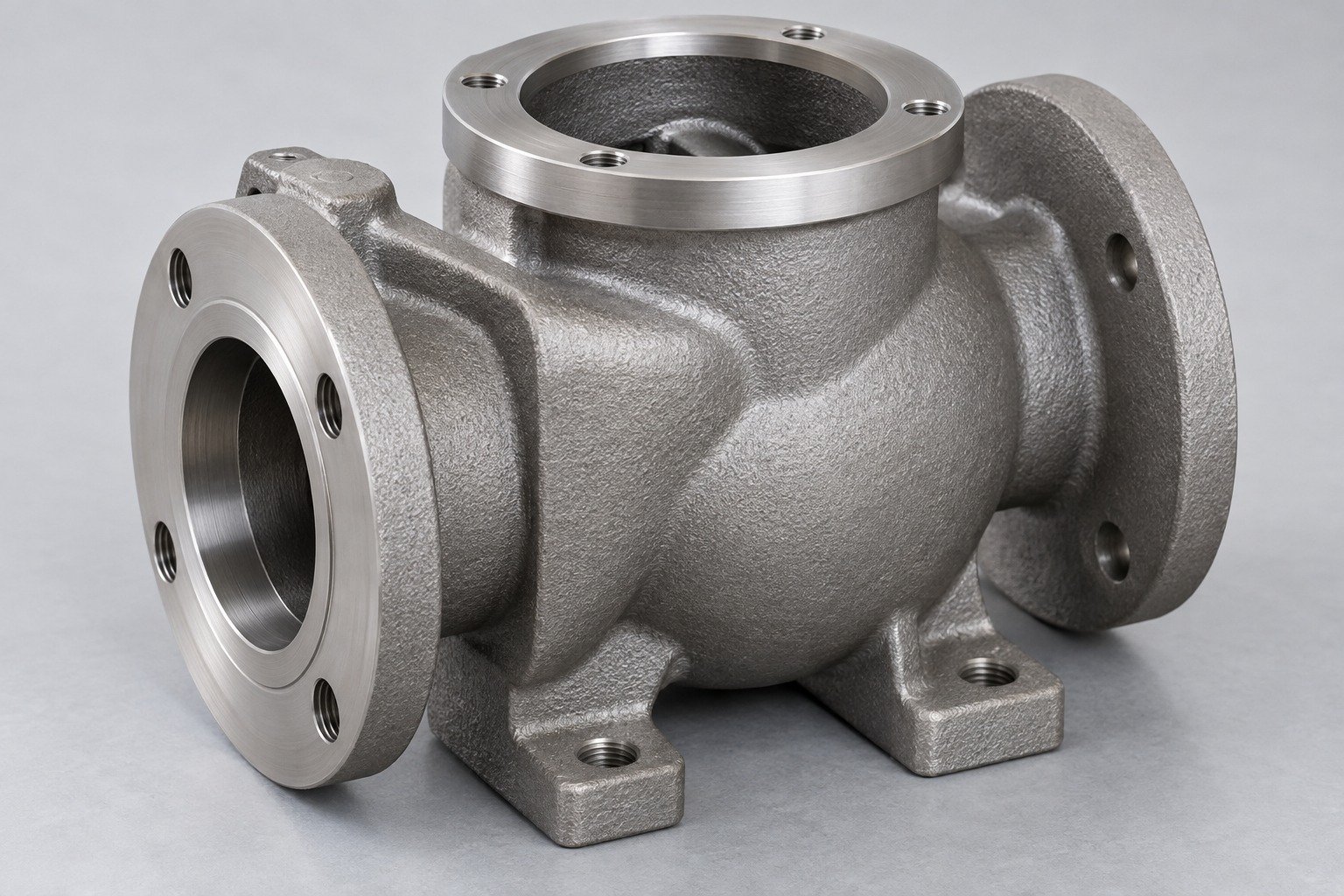
Specify the casting grade, heat-treatment condition and required properties.
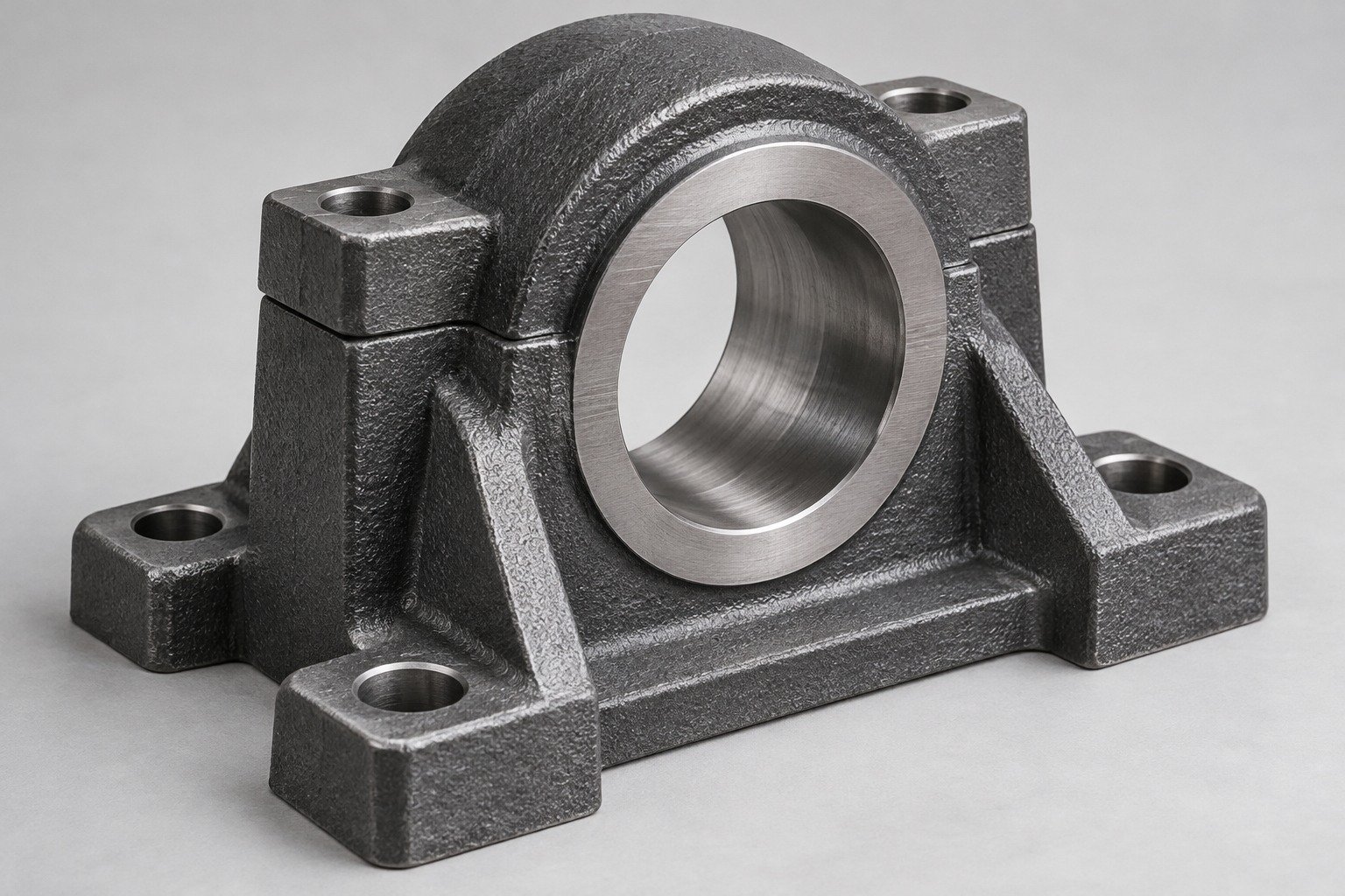
Identify iron type, casting grade and material acceptance requirements.
A sand casting pattern defines the external shape; a core box forms a core when internal features require one.
| Reusable tooling | Pattern and core box, where needed. |
|---|---|
| Expendable items | Sand mold and cores, where used, for each casting cycle. |
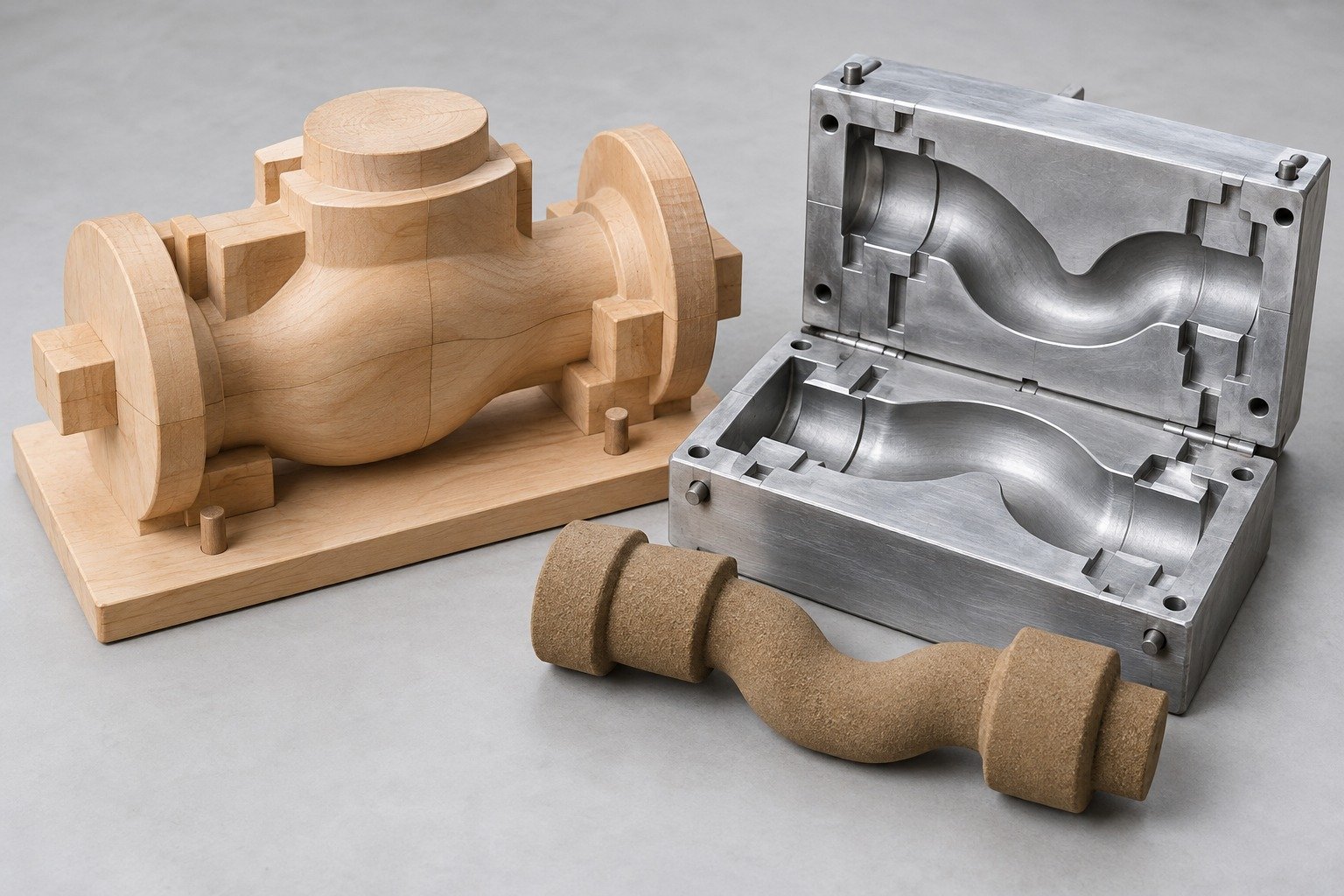
A clear sequence links your drawing, expendable mold, actual casting and final acceptance.
Design and review
Prepare sand mold
Controlled process
Remove sand and gates
CNC and finishing
Agreed evidence
Machining, heat treatment and finishing are included only when agreed in your project scope.
Use these sand casting design guidelines to identify your critical interfaces before tooling.
Review abrupt section changes and load-bearing fillets with the material and molding route. Avoid adopting a universal minimum wall.
Wall sections, loads and critical radii
Transitions, fillets and local cooling
Confirm methods, scope and acceptance limits for your part.
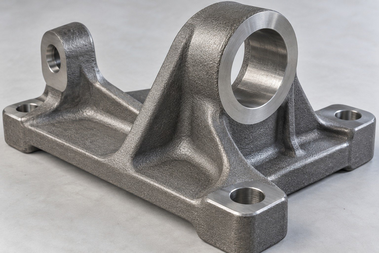
Define the draft angle for sand casting around pattern depth, withdrawal direction and your required surfaces.
Release direction and critical faces
Draft, parting and pattern withdrawal
Confirm methods, scope and acceptance limits for your part.
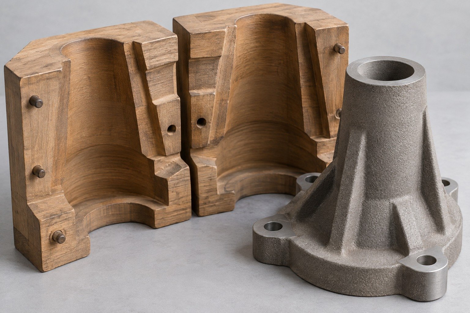
Identify core location, support, passage intersections and access for removing core material after casting.
Passages, intersections and clean-out zones
Core prints, support and removal access
Confirm methods, scope and acceptance limits for your part.
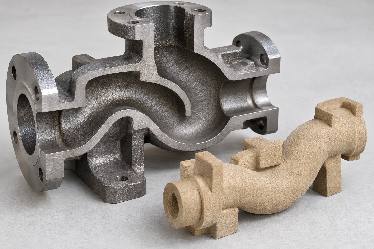
Review hot spots, section transitions and feeding access. Shrinkage compensation in the pattern does not replace soundness review.
Heavy sections and quality requirements
Feeding, hot spots and specified soundness checks
Confirm methods, scope and acceptance limits for your part.
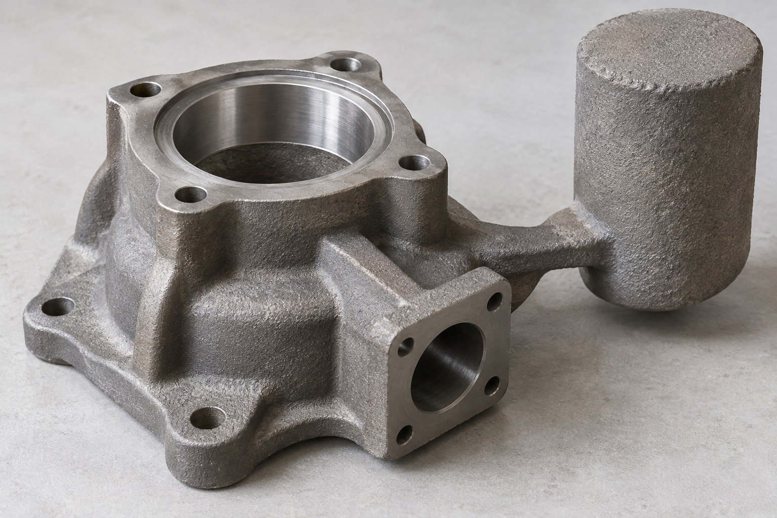
Identify the casting grade before setting the nominal casting geometry and machining stock.
EXAMPLE ONLY — NOT A RECOMMENDED ALLOWANCE
50.0 mm
2.0 mm
54.0 mm
Assumes stock on 2 opposite faces: 50.0 mm + (2 × 2.0 mm) = 54.0 mm. This is not a pattern dimension. Shrinkage compensation, draft and casting variation are reviewed separately.
Actual stock depends on grade, geometry, datums and the agreed molding route.
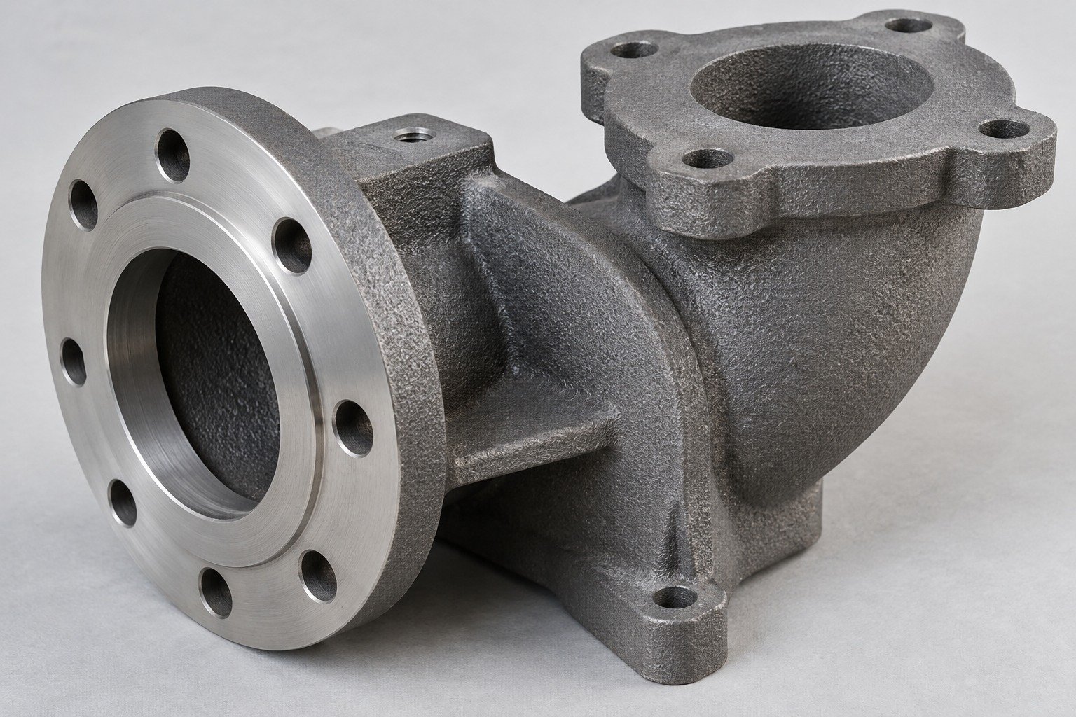
Review sand casting defects against your agreed limits. Surface discontinuities, porosity and internal indications need an inspection scope, not a zero-defect promise.
Surface limits and required internal tests
Acceptance zones, methods and repair permissions
Confirm methods, scope and acceptance limits for your part.
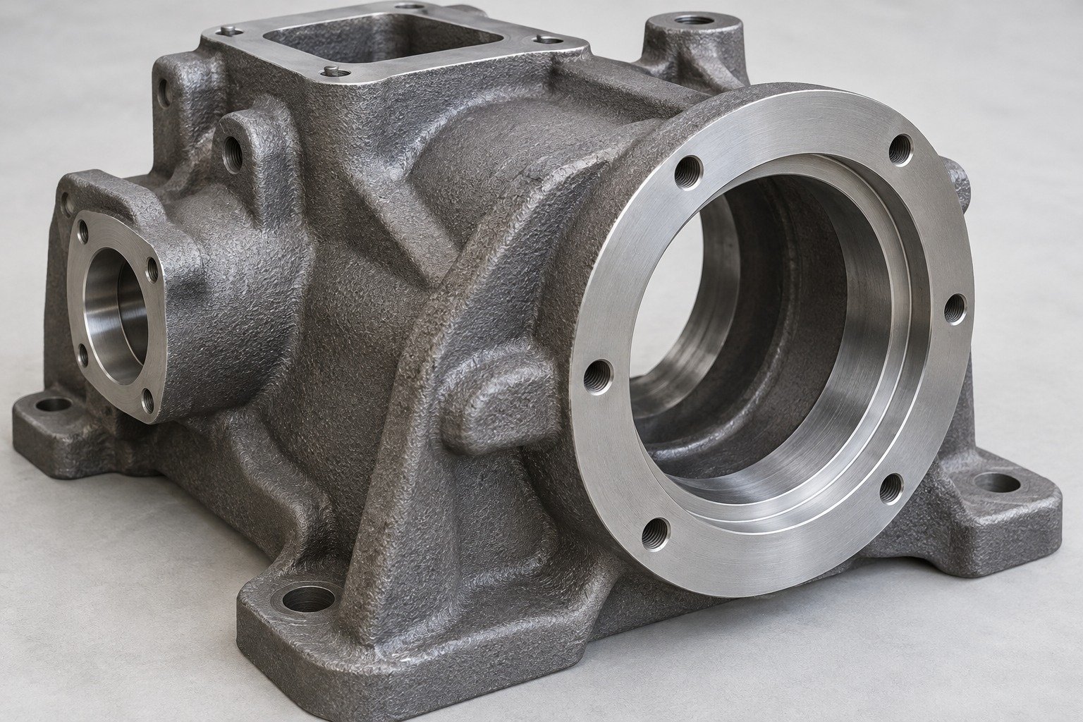
Set sand casting tolerances by feature, datum and delivery condition.
| Part state | Your key features | Review focus |
|---|---|---|
| As-cast | Walls, core position and locating stock | Agreed casting limits and inspection zones |
| Machined | Bores, threads and mating faces | Final drawing and datum scheme |
Specify sand casting surface finish on faces that remain unmachined. Approve texture, cleanup zones and machined surfaces separately; identify Ra or Rz and the measurement location when required.
Agree the records and acceptance limits you need before release.
Review the casting grade, delivery condition and material records against your controlled specification.
Assess sand casting defects by location, inspection method and acceptance limits. Agree special tests and repair permissions before production.
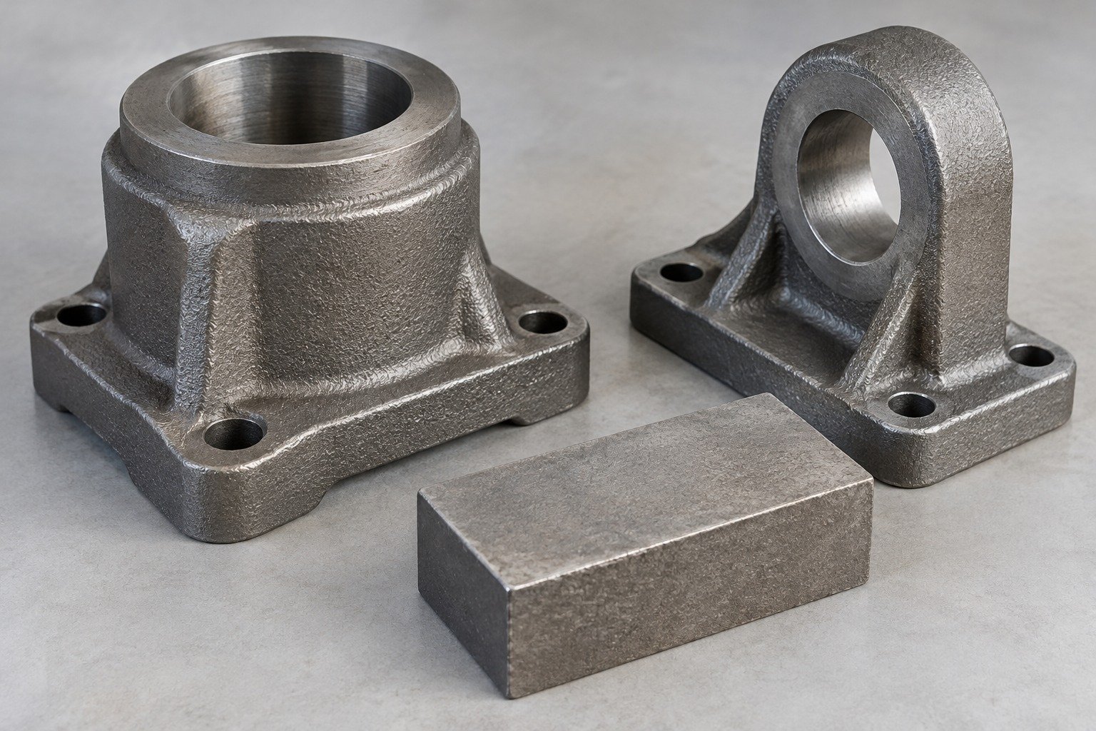
Plan prototype sand casting samples using the intended grade and molding route. A CNC-only model does not establish as-cast quality.
Assess sand casting defects by location, inspection method and acceptance limits. Agree special tests and repair permissions before production.
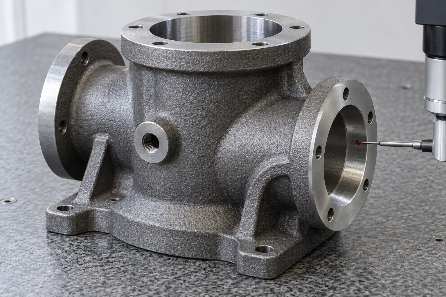
Check bores, threads, mating faces and datums after the specified secondary operations.
Assess sand casting defects by location, inspection method and acceptance limits. Agree special tests and repair permissions before production.
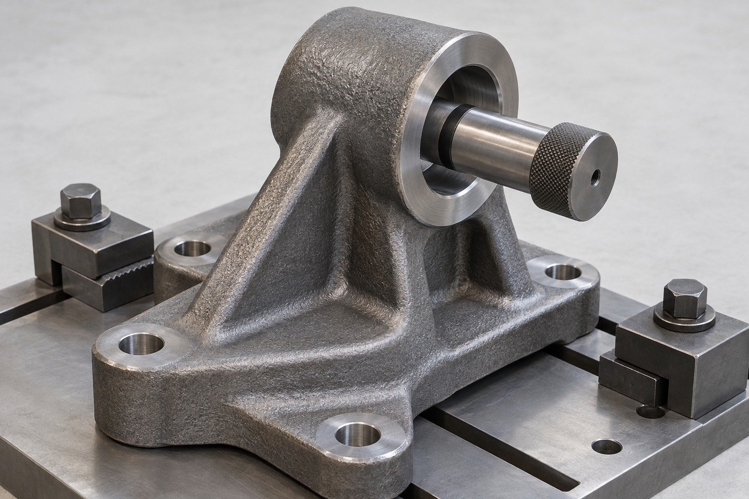
Review acceptance records, labels, part protection and shipping requirements before dispatch.
Assess sand casting defects by location, inspection method and acceptance limits. Agree special tests and repair permissions before production.
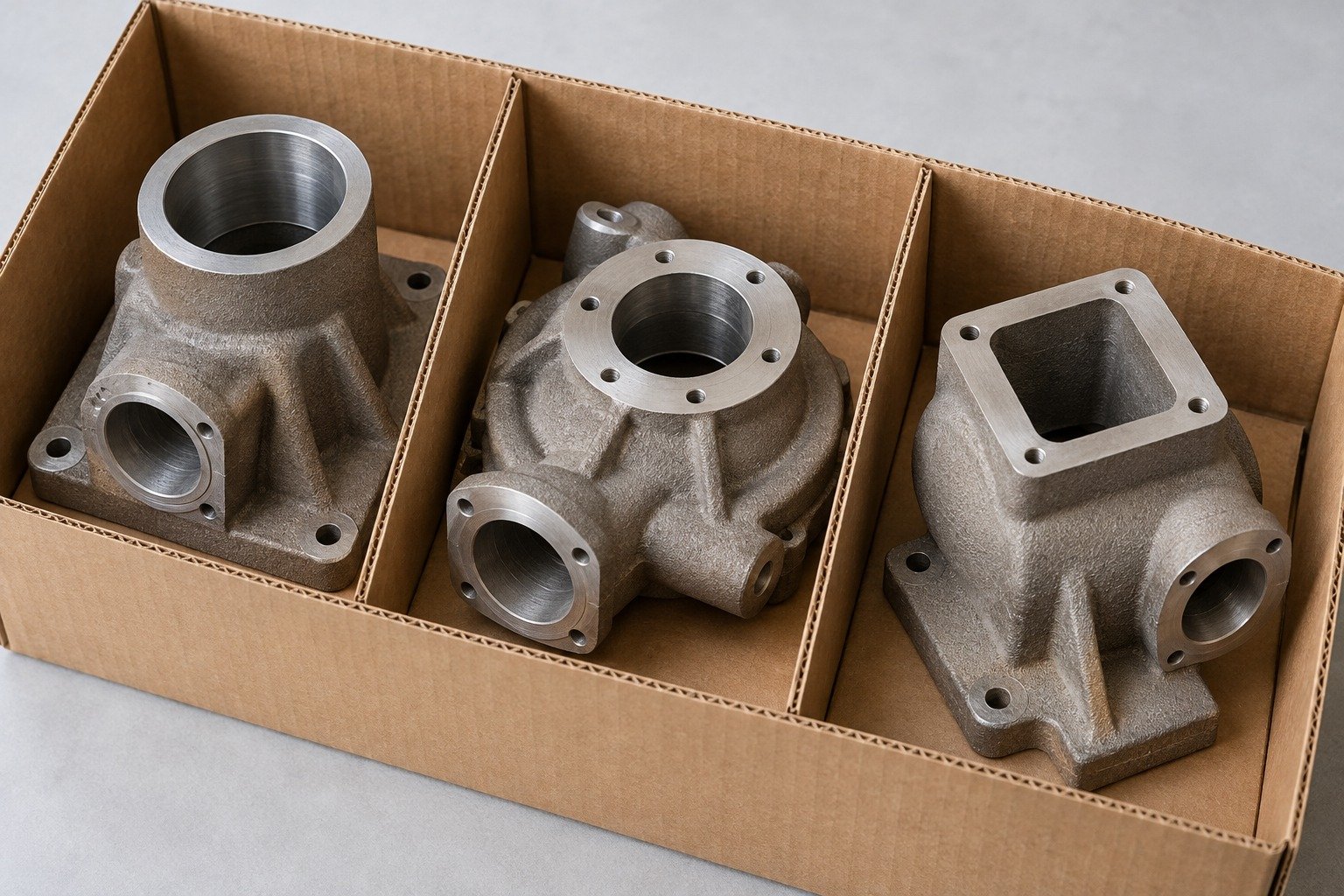
Review sand casting cost against the same drawing, material and acceptance scope.
EXAMPLE RFQ QUANTITIES — NOT MINIMUM ORDERS
Prototype / pilot comparison
Initial production comparison
Higher-volume comparison
Patterns & core boxes
Molds & cores
Metal & pouring
Secondary operations
Inspection
Delivery
Illustrative RFQ quantities, not minimum orders. Replace them with your actual demand; compare low volume sand casting against core-making and batch economics.
Review sand casting tooling cost, responsibilities and commercial terms with your sand casting supplier.
Who owns the pattern and core box, where it is stored and how it is protected.
Agree maintenance and expected service life for the actual tooling and route.
How design changes are charged, controlled and approved.
Conditions for future releases, tool transfer and replacement.
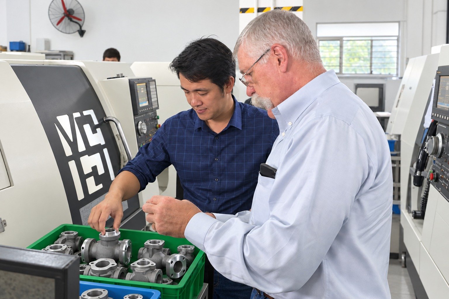
Coordinate drawing review, sample decisions and delivery with your project contact. Manufacturing scope and location are confirmed in your quotation.
Send the details that affect cost and acceptance.
Distinguish as-cast dimensions from machined features. Sand casting dimensional tolerances depend on size, grade, molding route and datum scheme. Confirm the agreed limits on your drawing before pattern release.
Share the tooling drawings, revision, condition and ownership records. Compatibility, wear, core prints and the intended molding route must be reviewed before accepting an existing tool.
Confirm separate milestones for drawing approval, patterns and core boxes, trial castings, any heat treatment, machining and sample acceptance. Production and transport follow the agreed release plan; timing is confirmed for your project.
The economic batch depends on tooling, grade, geometry, cores and acceptance scope. Request a comparison at your trial, first-order and repeat quantities. The example quantities on this page are not minimum orders.
As-cast texture, dimensional variation, core-making and cleanup can add work. Critical fits often need machining. Compare the total finished-part cost and acceptance plan rather than the casting price alone.
Yes, where the casting grade and geometry suit the operation. Identify stock, locating datums, bore and thread requirements, fixture access and the final inspection state. Include the specified machining in your quotation.
Compare alloy, cored geometry, part size, finished surface, tooling investment and demand. Sand molds are expendable; pressure die casting uses a reusable metal die. Review the finished-part requirements before choosing a route.