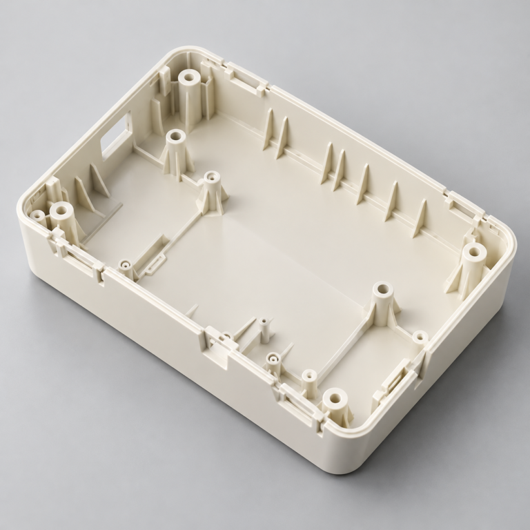
Injection Molding
Tooling and molding for your repeat plastic parts.
From prototype to production, coordinated manufacturing solutions for your custom parts.
View All Services →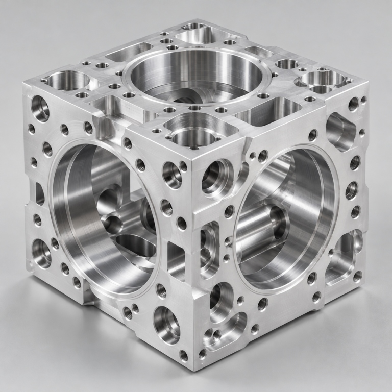
Precision parts for your tight tolerances and complex geometry.
Tooling and molding for your repeat plastic parts.
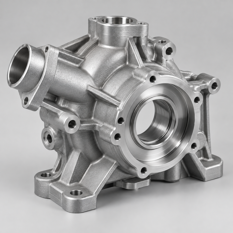
Metal casting options for your part and production volume.
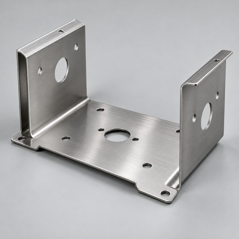
Cutting, forming and welding for your fabricated parts.
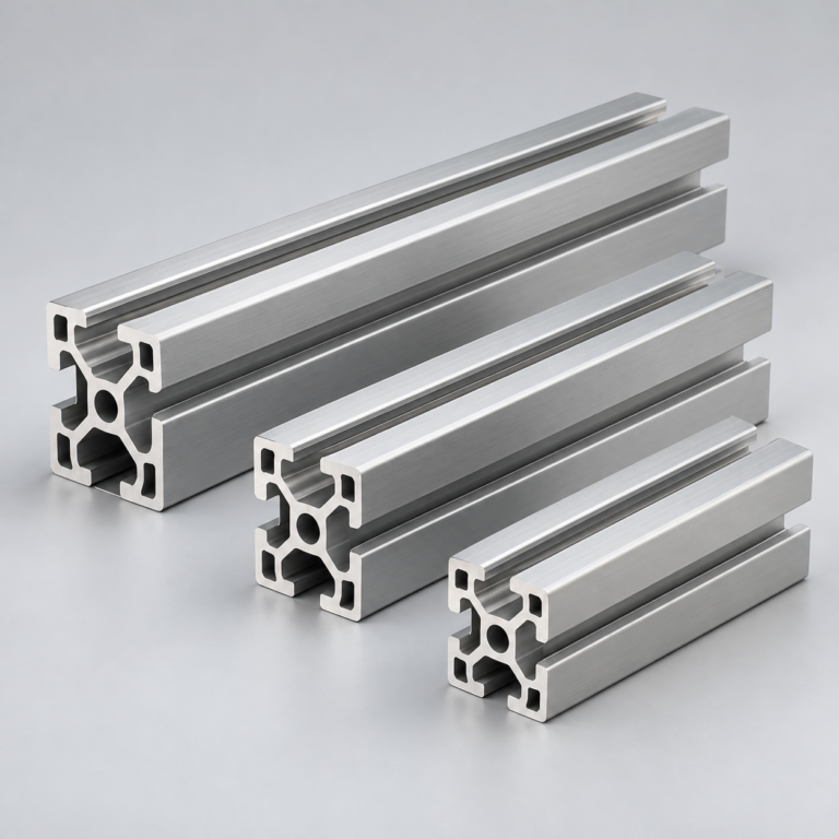
Custom profiles for your section, length and finish requirements.
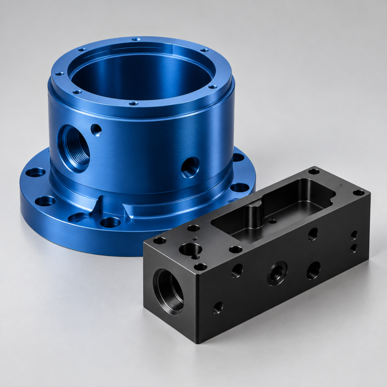
Finishes for your appearance, corrosion and wear requirements.
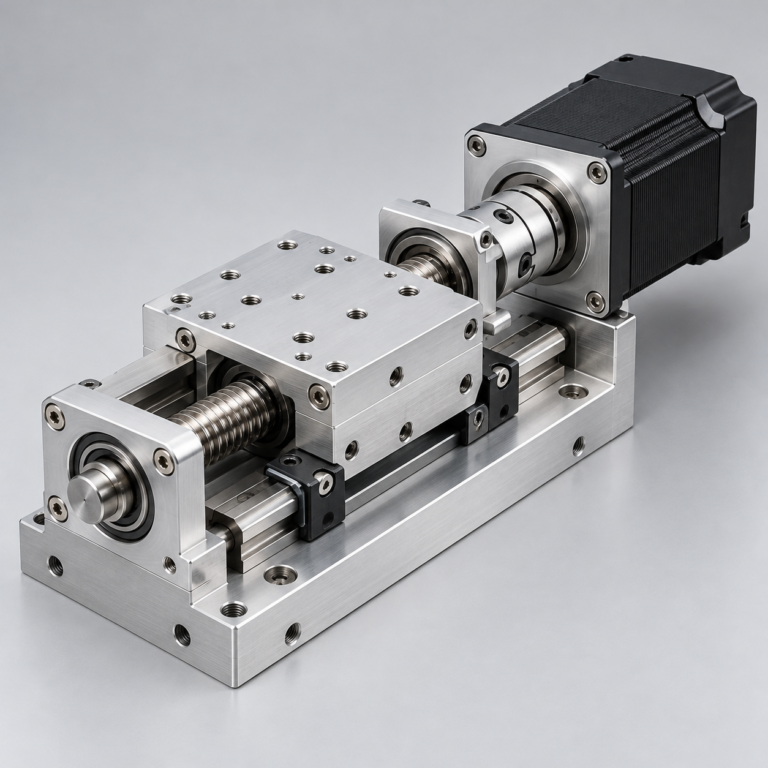
Sub-assemblies and final builds for your production program.
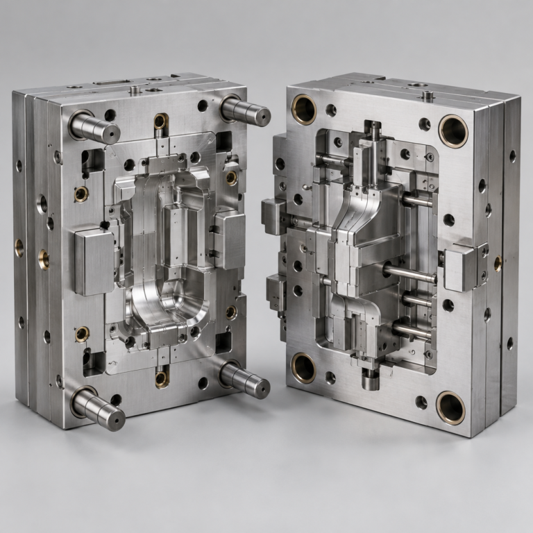
Production tooling built around your process and volume.
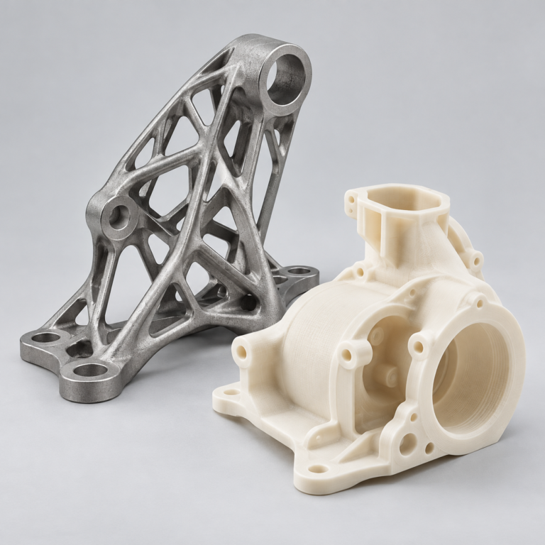
Prototype parts to check fit, function and design.
Choose air- or liquid-cooling components around your thermal and mechanical requirements.
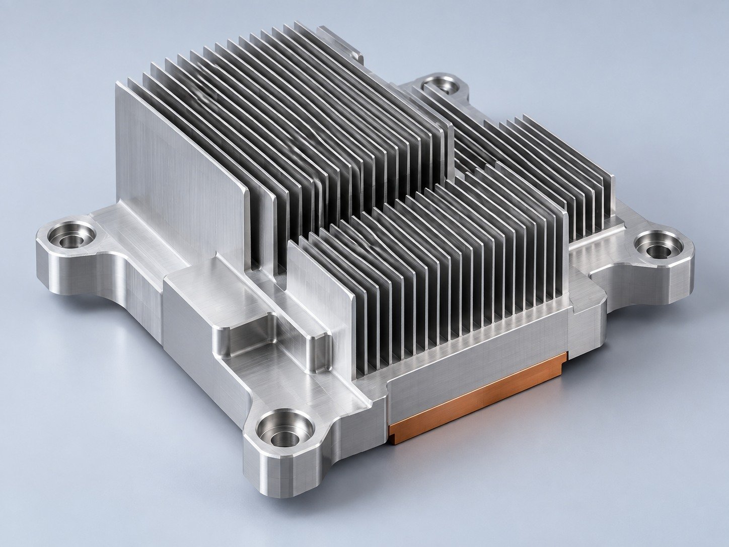
Manufacturing support for your cold plates, manifolds and cooling assemblies.
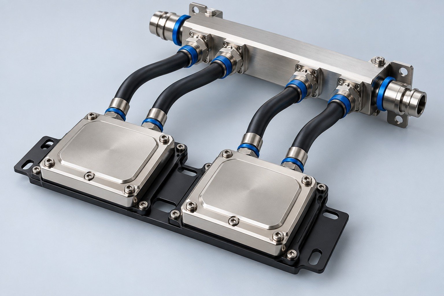
Find components for your power electronics, energy, laser and telecom application.
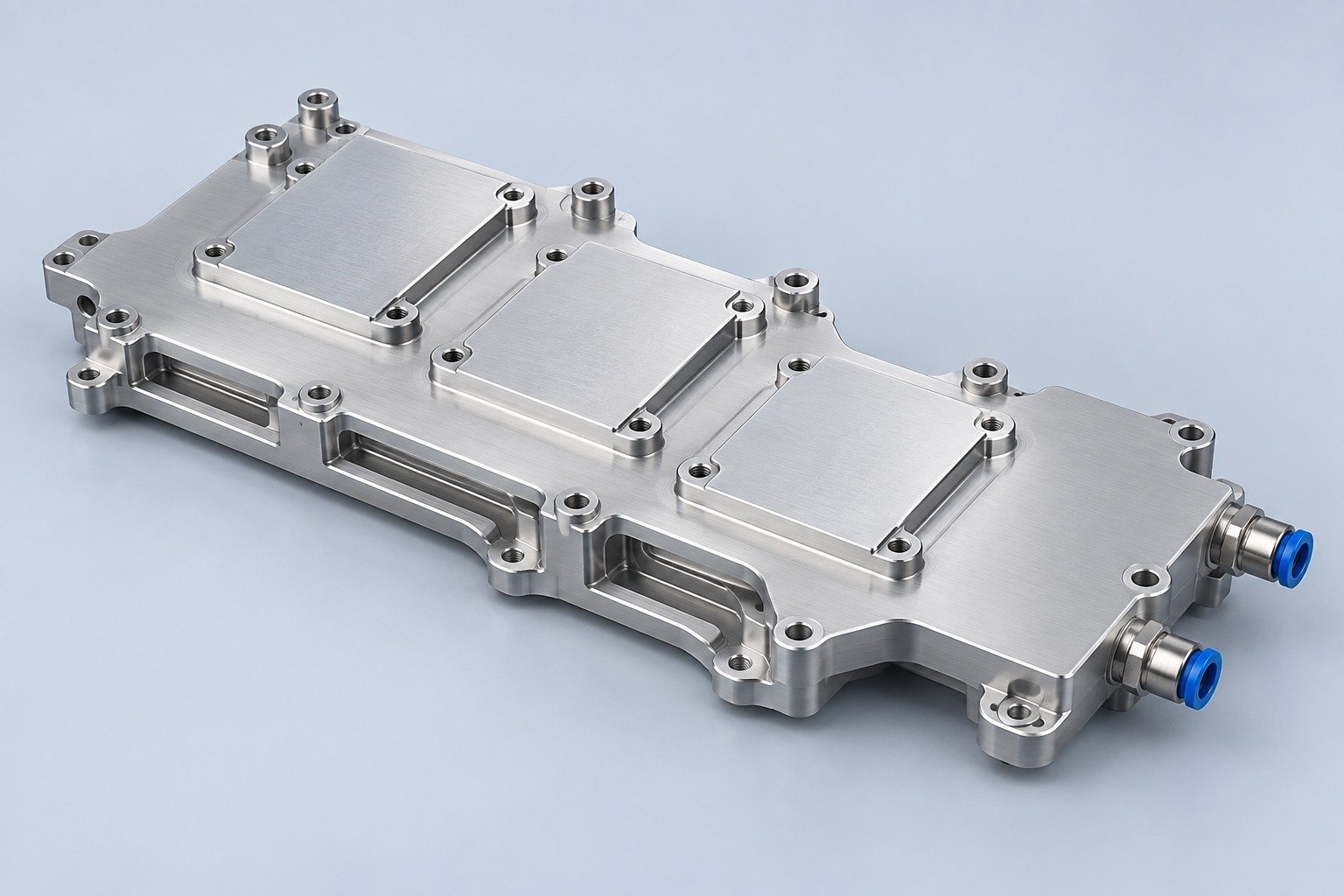
Components for your electronic systems.
Start with your functional and quality requirements.
Build around your operating environment.
From prototype to production, review material performance, manufacturability and cost for your part.
Review grade, temper and finish for your metal parts.
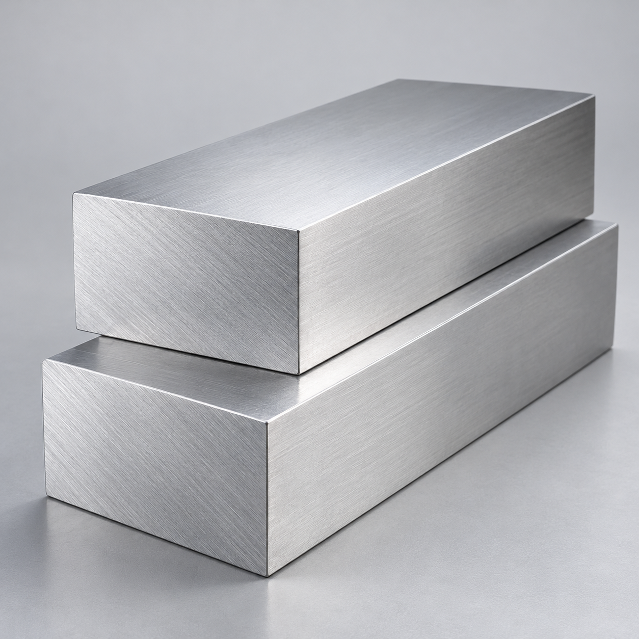 AluminumStrength, weight and machining›
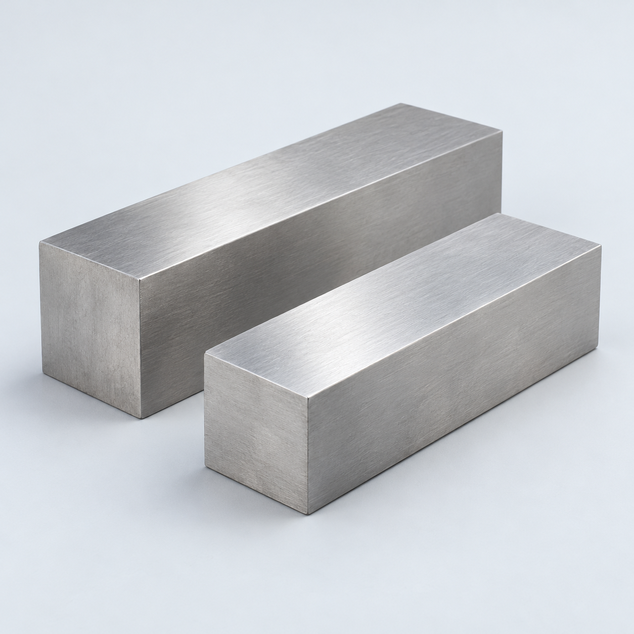 Stainless SteelCorrosion and finish requirements›
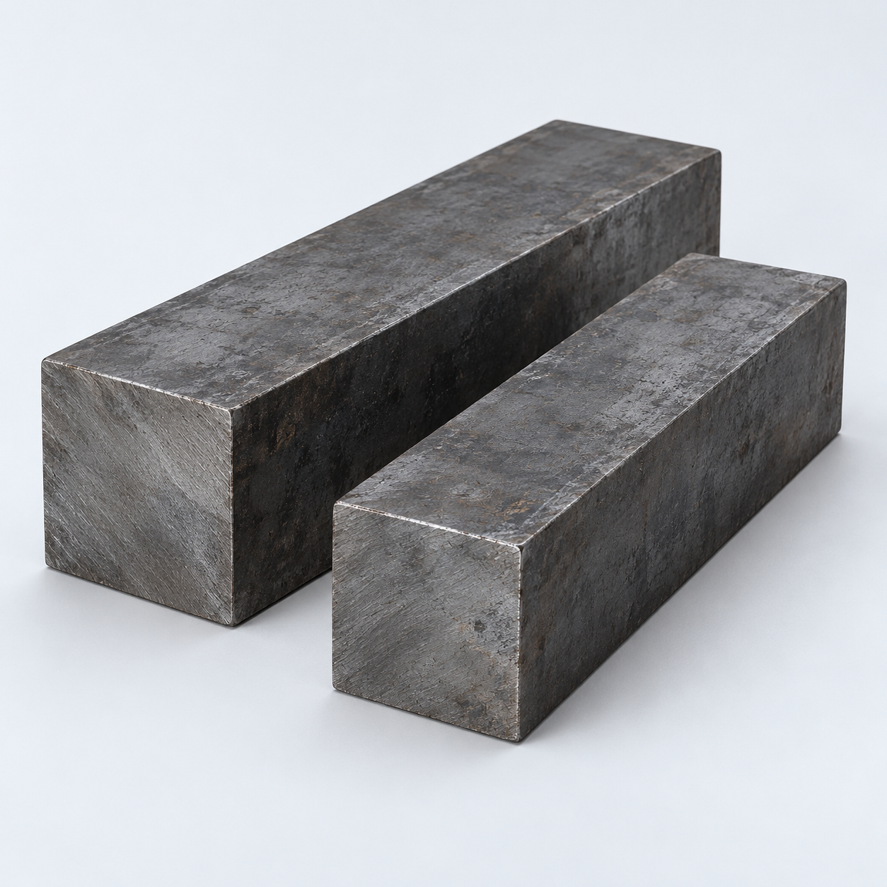 Carbon & Alloy SteelDiscuss grade and heat treatment›
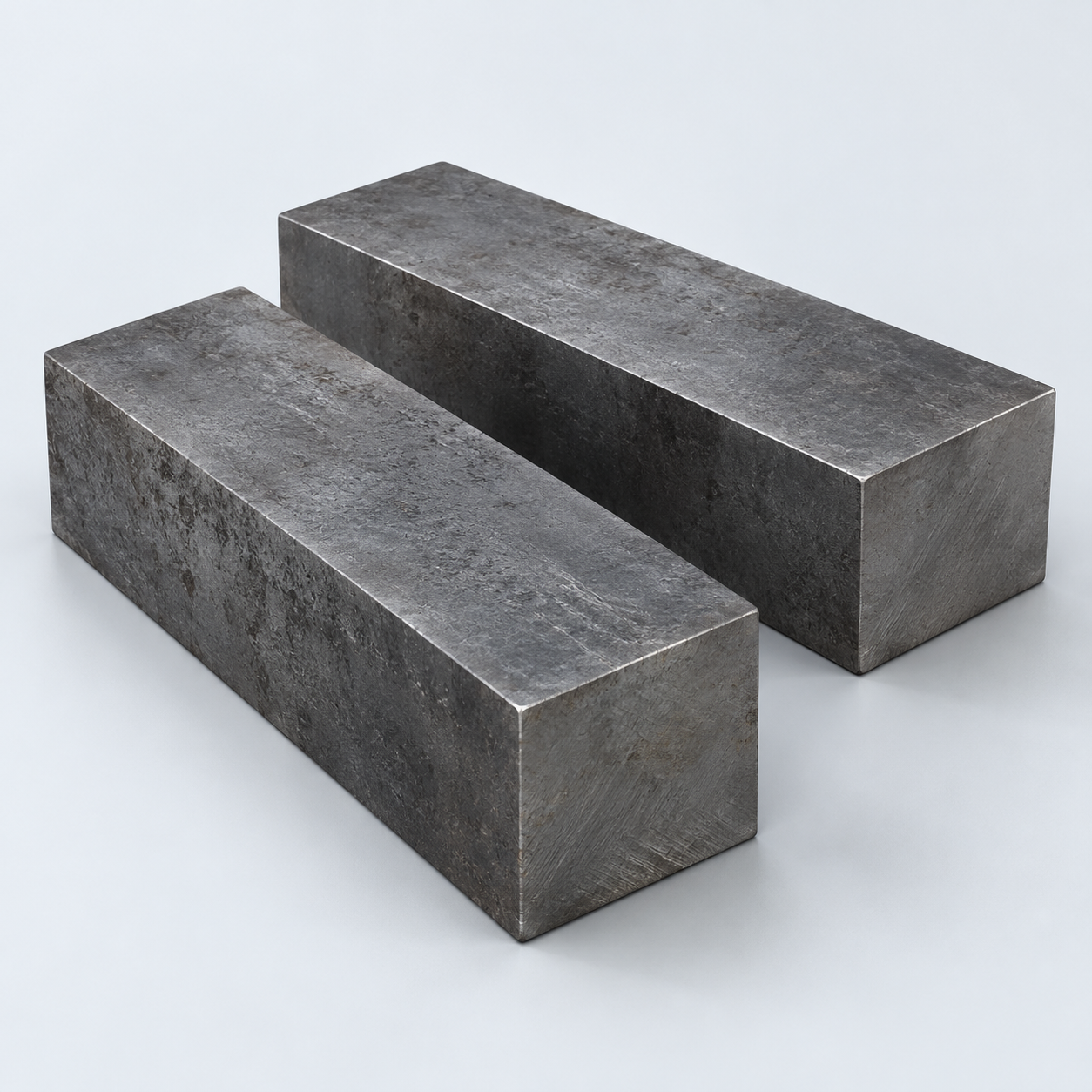 Tool SteelDiscuss tooling and wear needs›
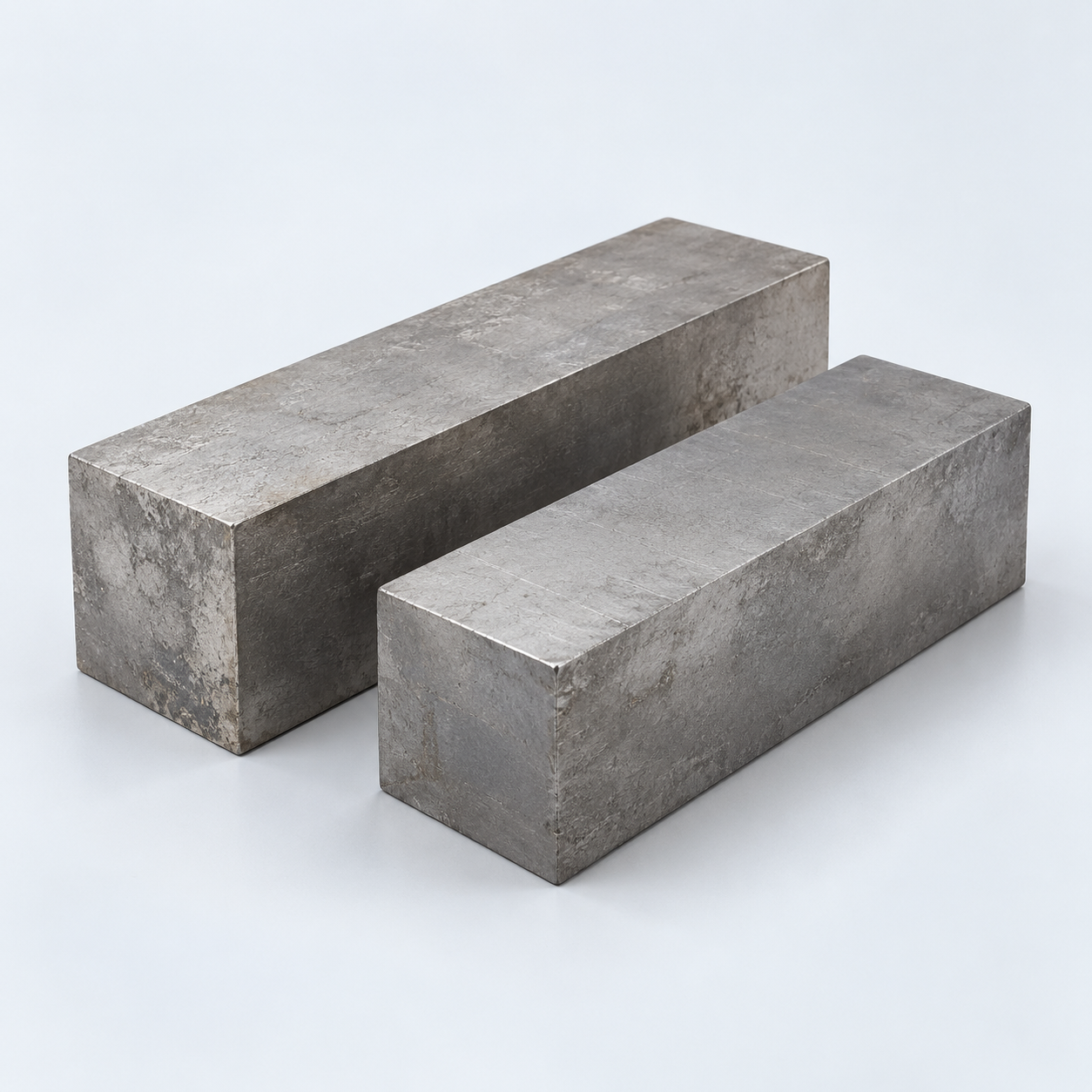 TitaniumReview grade and part geometry›
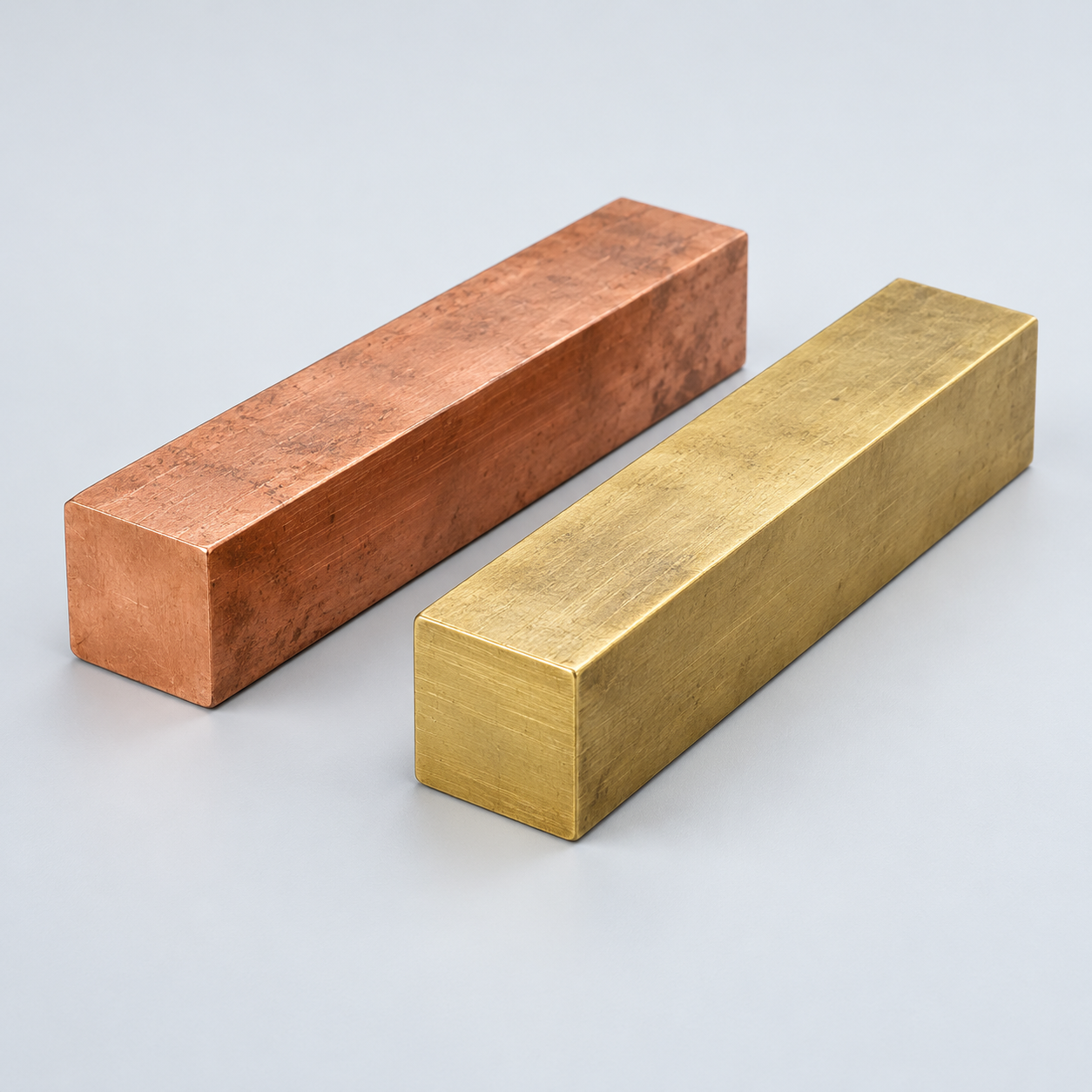 Copper & BrassDiscuss conductivity and machining›
Match your polymer to function, process and environment.
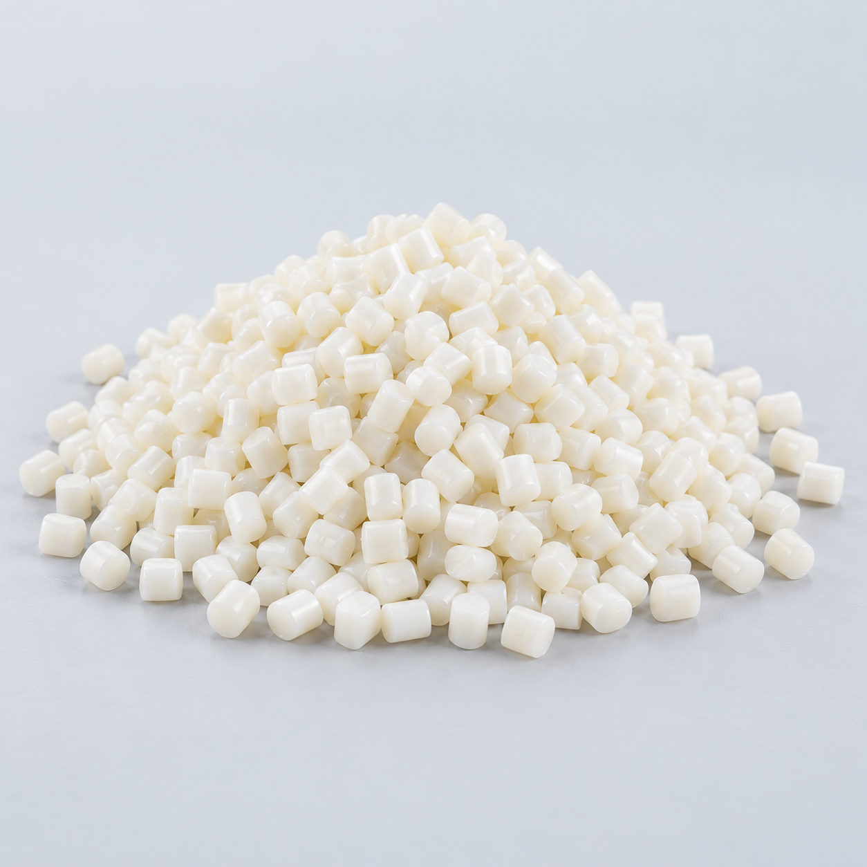 ABSReview enclosure and molding needs›
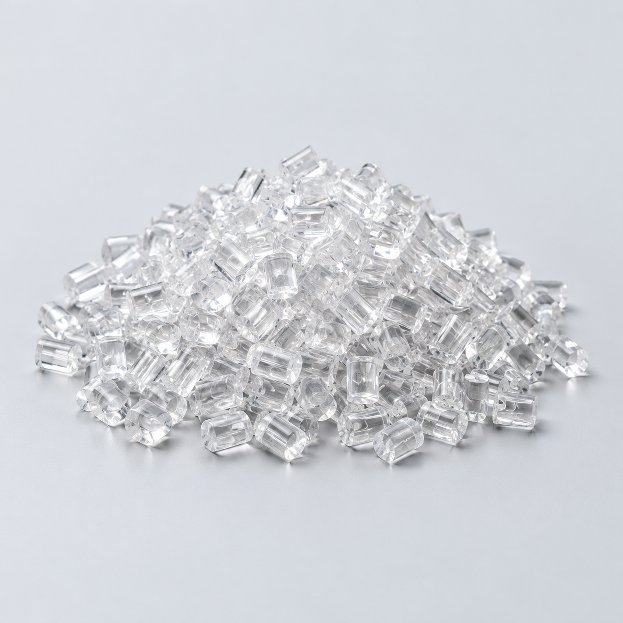 Polycarbonate (PC)Discuss clarity and impact needs›
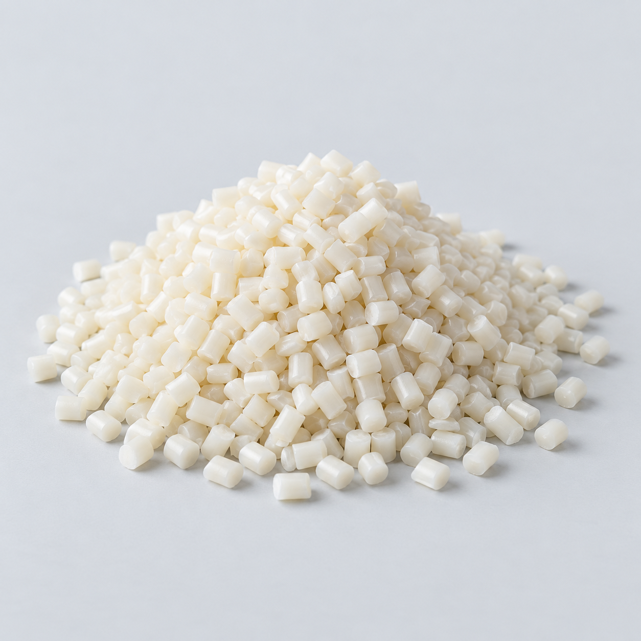 Nylon (PA)Review moisture and wear conditions›
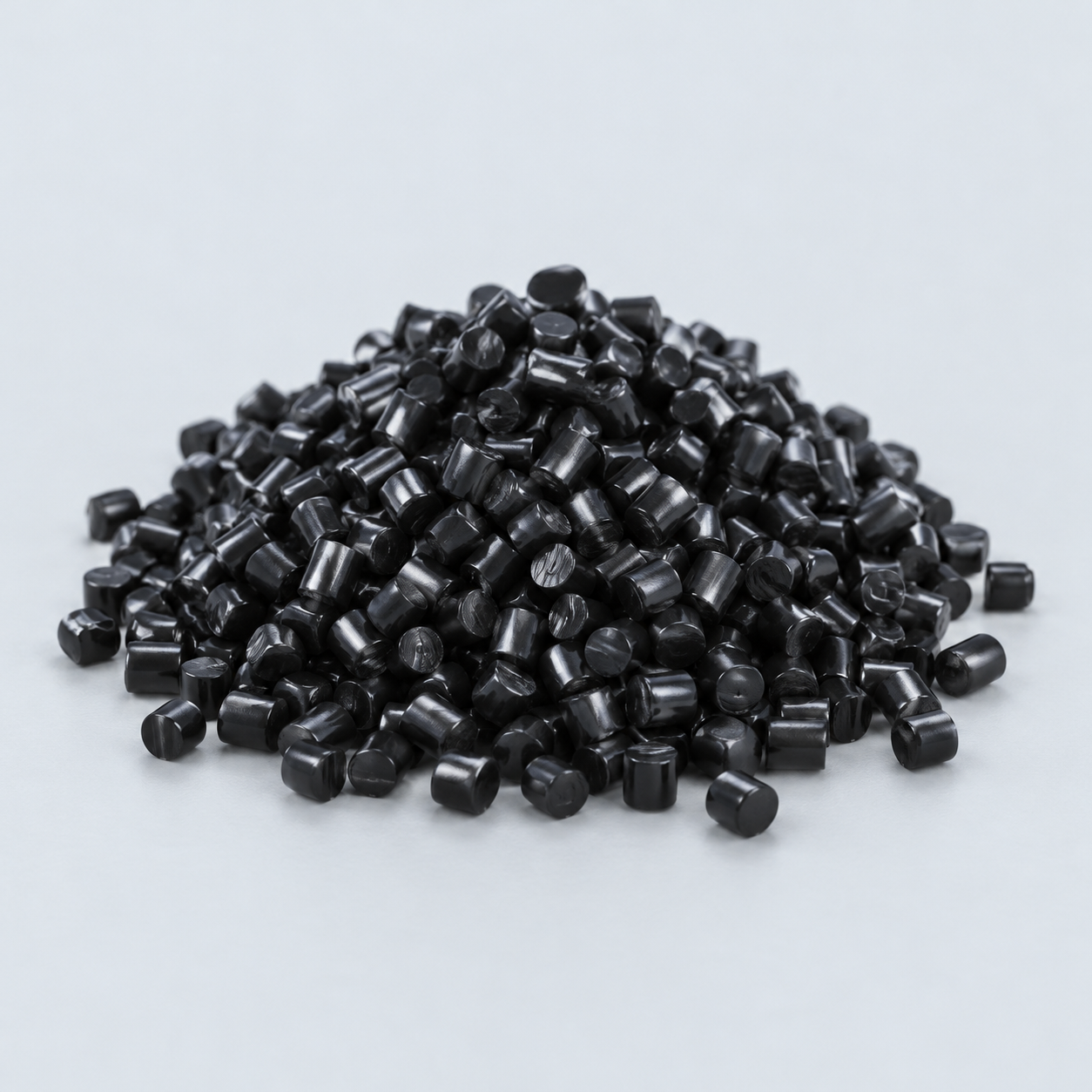 POM / AcetalReview fit and sliding features›
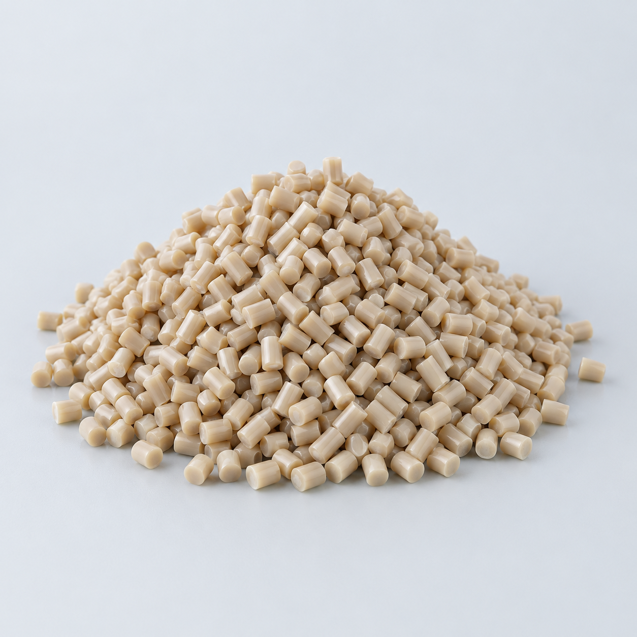 PEEKDiscuss operating conditions›
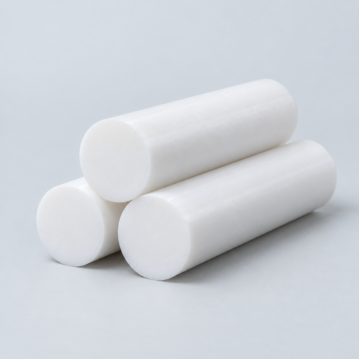 PTFEReview friction and chemical exposure›
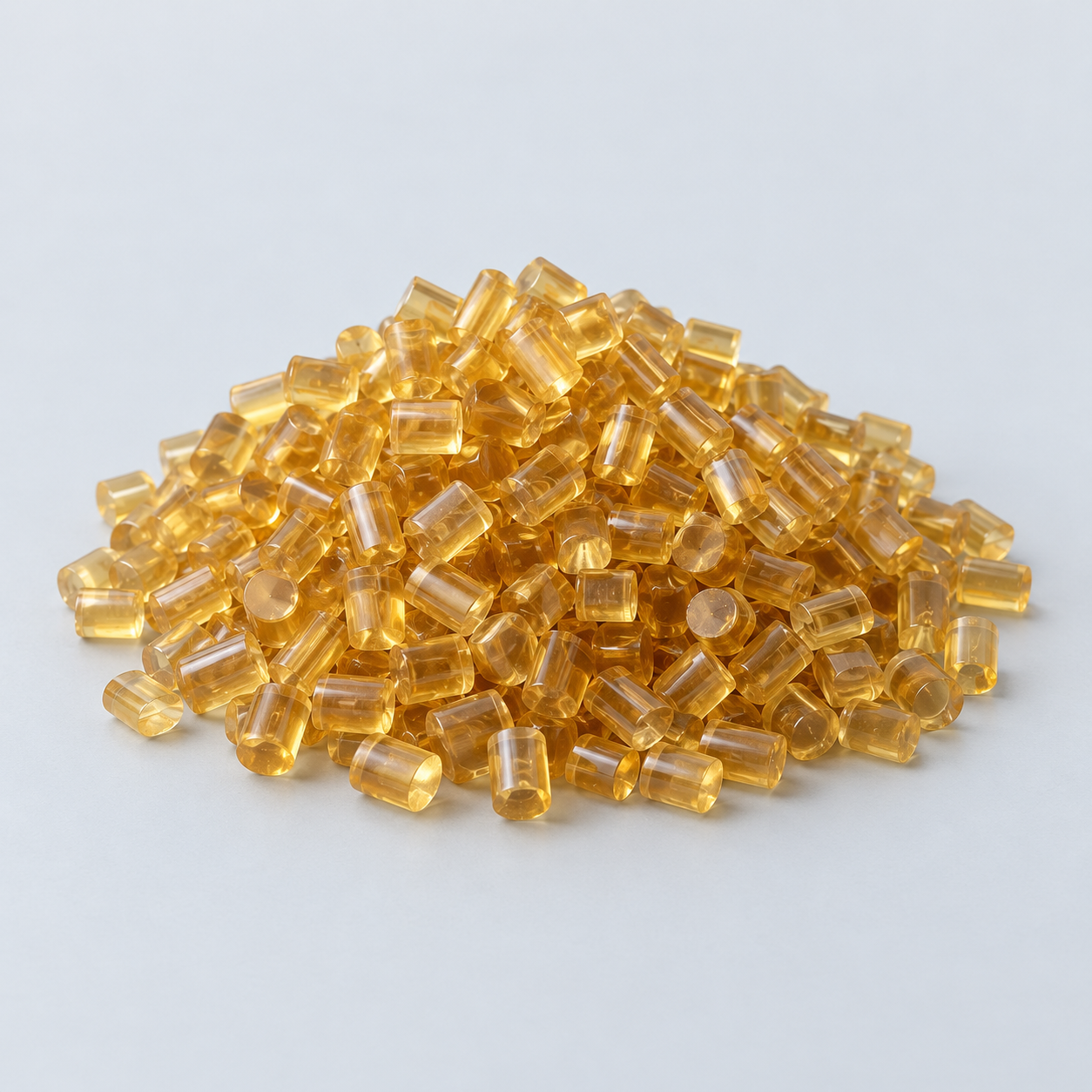 ULTEM / PEIDiscuss thermal and electrical needs›
Confirm grade availability and application requirements.
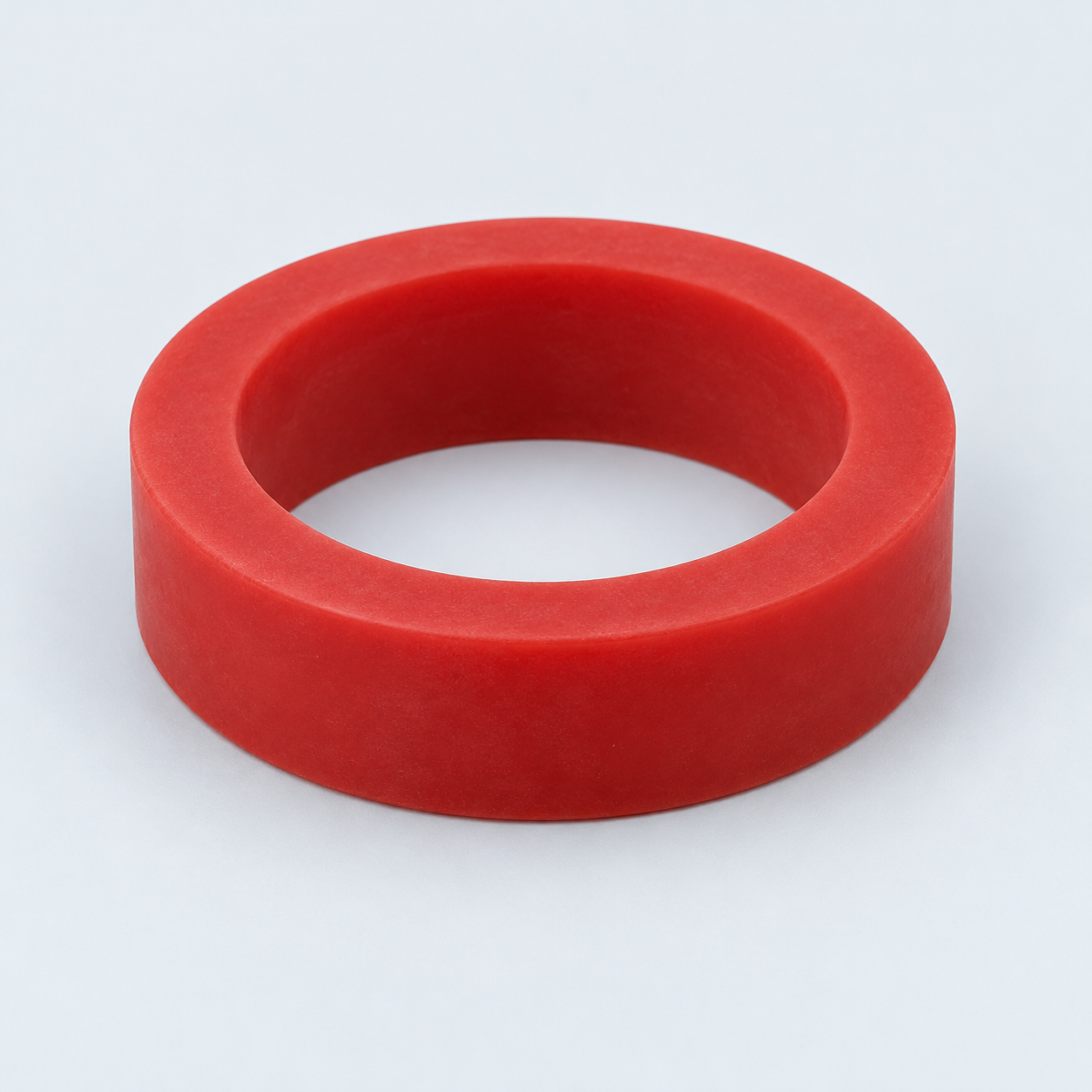 Silicone / LSRDiscuss flexible component needs›
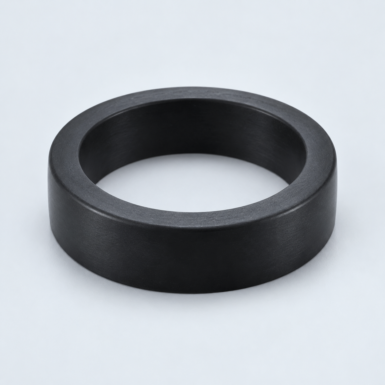 TPU / TPEReview flexibility and processing›
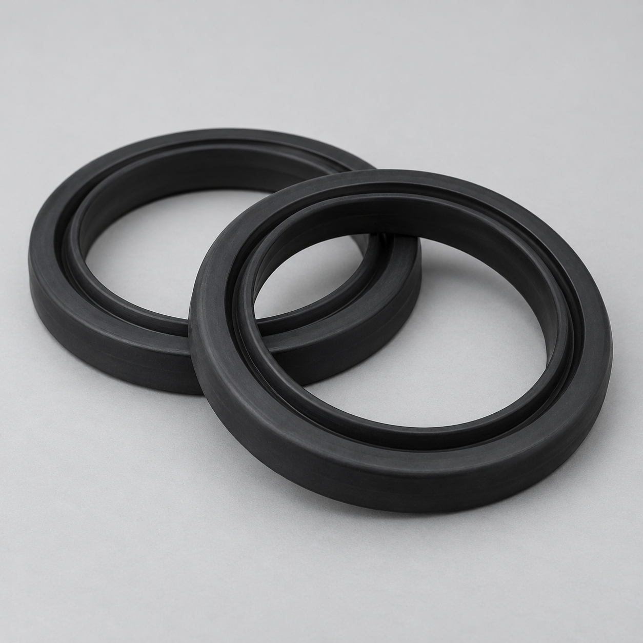 EPDMReview weathering and chemical exposure.›
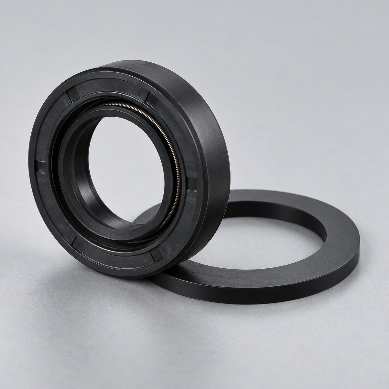 NBRReview oil and fuel exposure.›
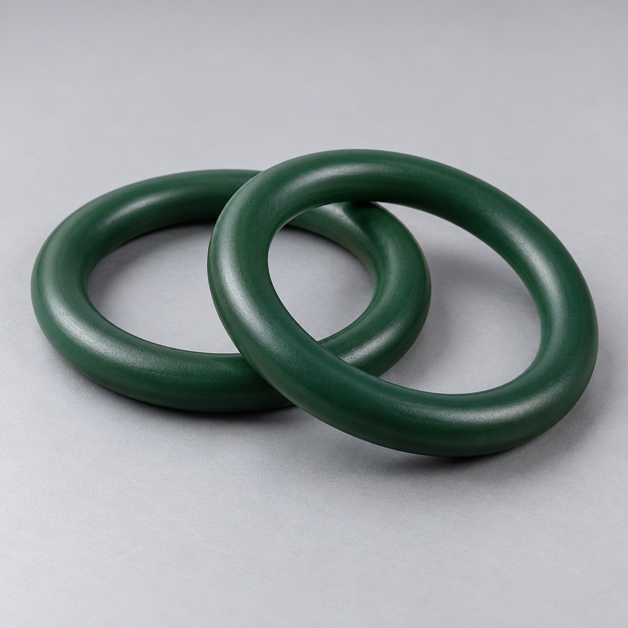 FKMReview temperature and chemical exposure.›
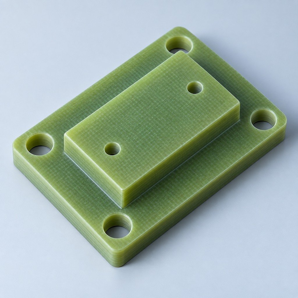 G10 / FR4Review insulation and laminate needs›
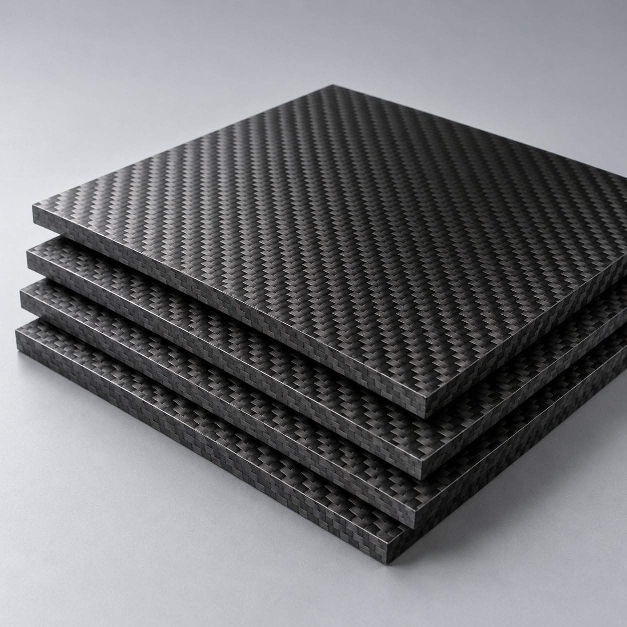 CompositesReview stiffness, weight and laminate.›Customer-Specified MaterialsConfirm your grade and requirements.›Other Specialty MaterialsDiscuss your application and grade.›
Practical guidance for your part geometry and material decisions.
Prepare your process, budget and sourcing questions.
Build your knowledge before production.
Learn who we are and how we operate.
Find our U.S. support team or start a conversation.
YOUR DRAWING. YOUR ALLOY. YOUR ACCEPTANCE PLAN.
Plan custom aluminum die casting parts around your alloy, critical interfaces and demand. Review tooling, machining and sample requirements before committing to production.
Start with CAD model + controlled 2D drawing.
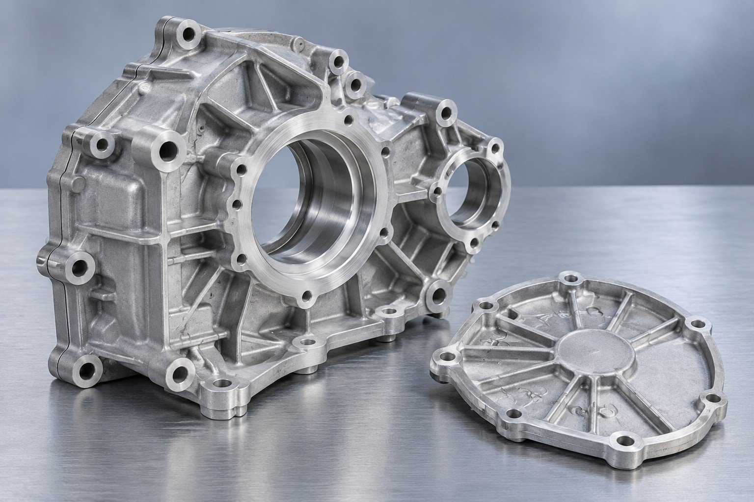
Find the grade for your requirements.
New tools or existing-tool review.
Critical dimensions and datums.
Trial parts and agreed checks.
Dallas-area project support.
Define your requirements early to reduce revisions, clarify cost and plan your release.
Grade, environment and finish.
Cast geometry versus machined features.
Trial quantity, first order and annual volume.
High pressure aluminum die casting injects molten alloy into a reusable steel die. Review the route around your geometry and order quantities.
Mark sealing faces, bores and threads on your controlled drawing.
| For your function | Environment and mating parts |
|---|---|
| For your fit | Datums and critical dimensions |
| For your supply | Trial, first order and annual demand |
Part geometry and manufacturing scope are reviewed with your drawing.
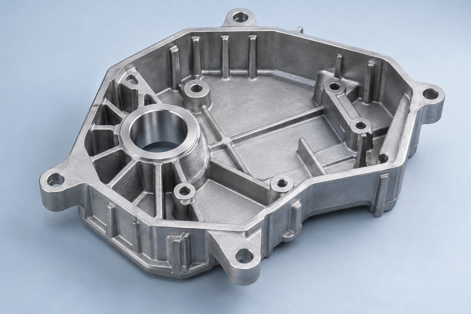
Compare aluminum die casting alloys with your corrosion, thermal, mechanical and finish requirements.
| Your specification | Grade, standard and required material records |
|---|---|
| Your environment | Temperature, fluids and exposure |
| Your finish | Surface sample, coating and masking |
Part geometry and manufacturing scope are reviewed with your drawing.
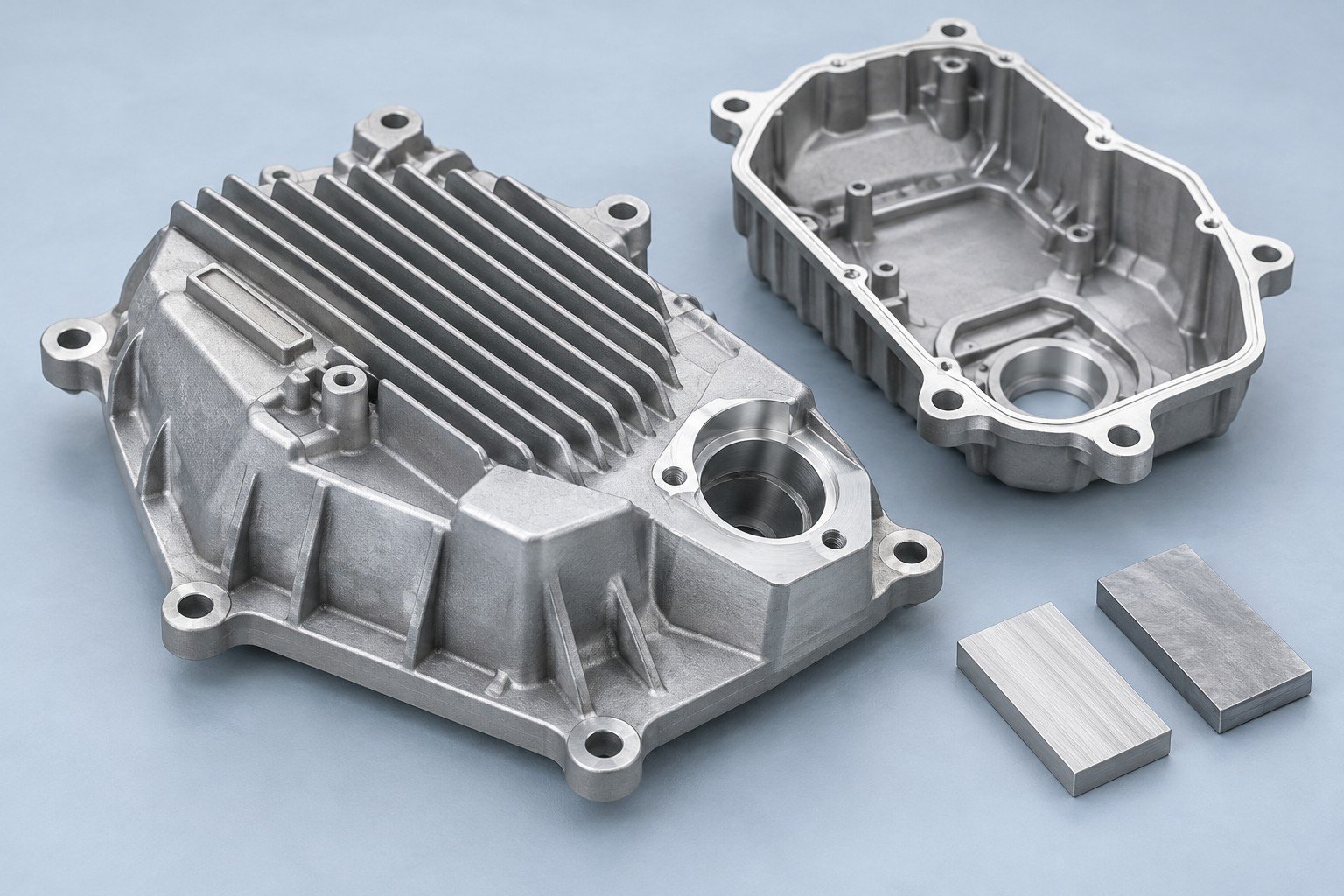
Plan aluminum die casting with secondary machining for your bores, threads and sealing faces.
| Your drawing | Datums, tolerances and machining symbols |
|---|---|
| Your allowance | Stock and access on machined features |
| Your check | Measurement method and support |
Part geometry and manufacturing scope are reviewed with your drawing.
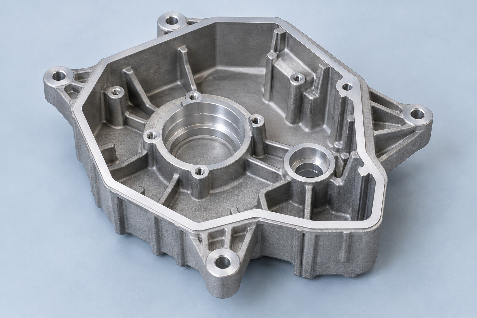
Agree dimensions, appearance and functional checks before the trial run.
| Your dimensions | Critical interfaces and measurement conditions |
|---|---|
| Your appearance | Finish sample and visible surface zones |
| Your function | Loads, leak conditions or assembly checks |
Part geometry and manufacturing scope are reviewed with your drawing.
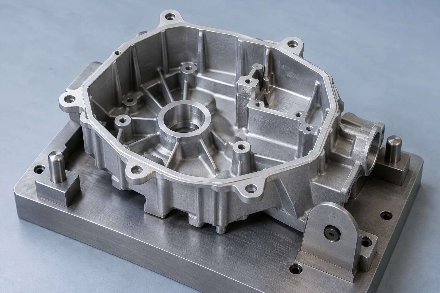
Define the heat path, mounting features and exposure for your lighting body.
| For your function | Heat path and working temperature |
|---|---|
| For your fit | Thermal contact and mounting faces |
| For your supply | Finish and exposure requirements |
Part geometry and manufacturing scope are reviewed with your drawing.
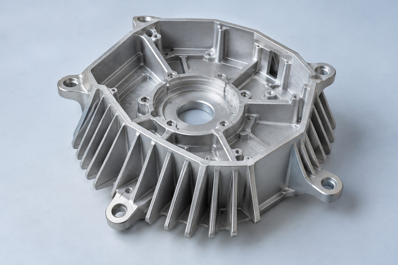
Compare aluminum die casting alloys with your corrosion, thermal, mechanical and finish requirements.
| Your specification | Grade, standard and required material records |
|---|---|
| Your environment | Temperature, fluids and exposure |
| Your finish | Surface sample, coating and masking |
Part geometry and manufacturing scope are reviewed with your drawing.
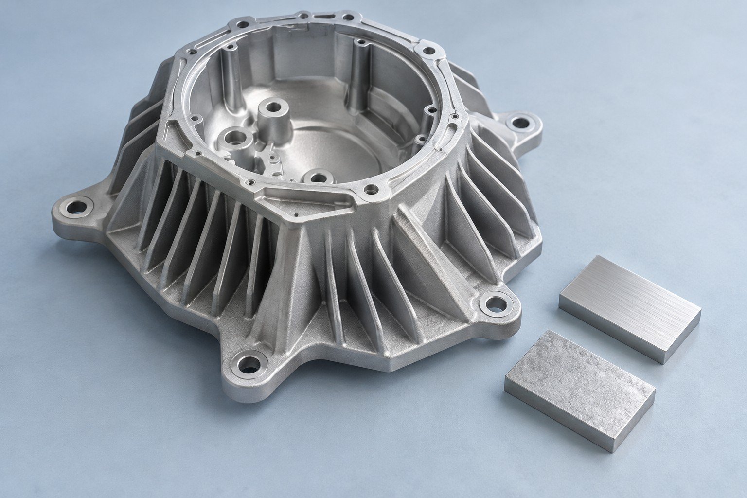
Plan aluminum die casting with secondary machining for your bores, threads and sealing faces.
| Your drawing | Datums, tolerances and machining symbols |
|---|---|
| Your allowance | Stock and access on machined features |
| Your check | Measurement method and support |
Part geometry and manufacturing scope are reviewed with your drawing.
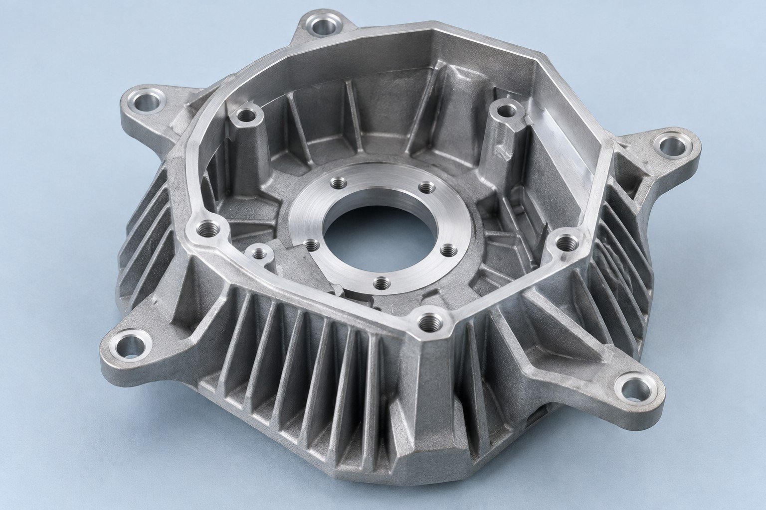
Agree dimensions, appearance and functional checks before the trial run.
| Your dimensions | Critical interfaces and measurement conditions |
|---|---|
| Your appearance | Finish sample and visible surface zones |
| Your function | Loads, leak conditions or assembly checks |
Part geometry and manufacturing scope are reviewed with your drawing.
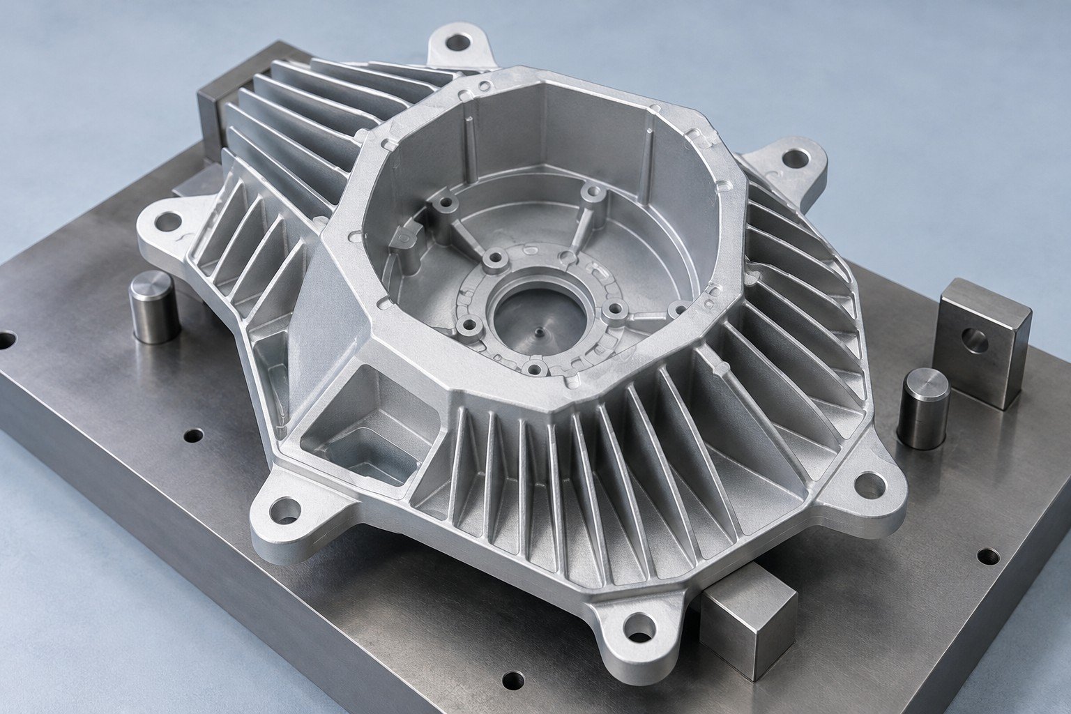
Identify bearing bores, mounting datums and assembly clearances.
| For your function | Motor load and operating environment |
|---|---|
| For your fit | Bearing alignment and mounting datums |
| For your supply | Sample checks and repeat-order needs |
Part geometry and manufacturing scope are reviewed with your drawing.
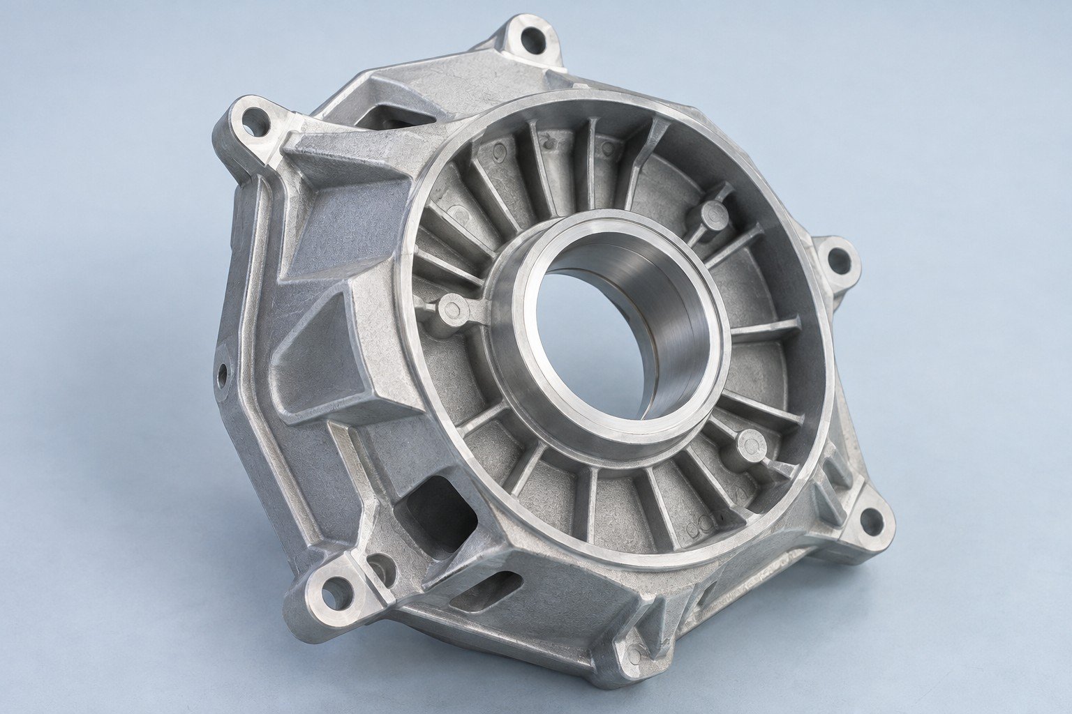
Compare aluminum die casting alloys with your corrosion, thermal, mechanical and finish requirements.
| Your specification | Grade, standard and required material records |
|---|---|
| Your environment | Temperature, fluids and exposure |
| Your finish | Surface sample, coating and masking |
Part geometry and manufacturing scope are reviewed with your drawing.
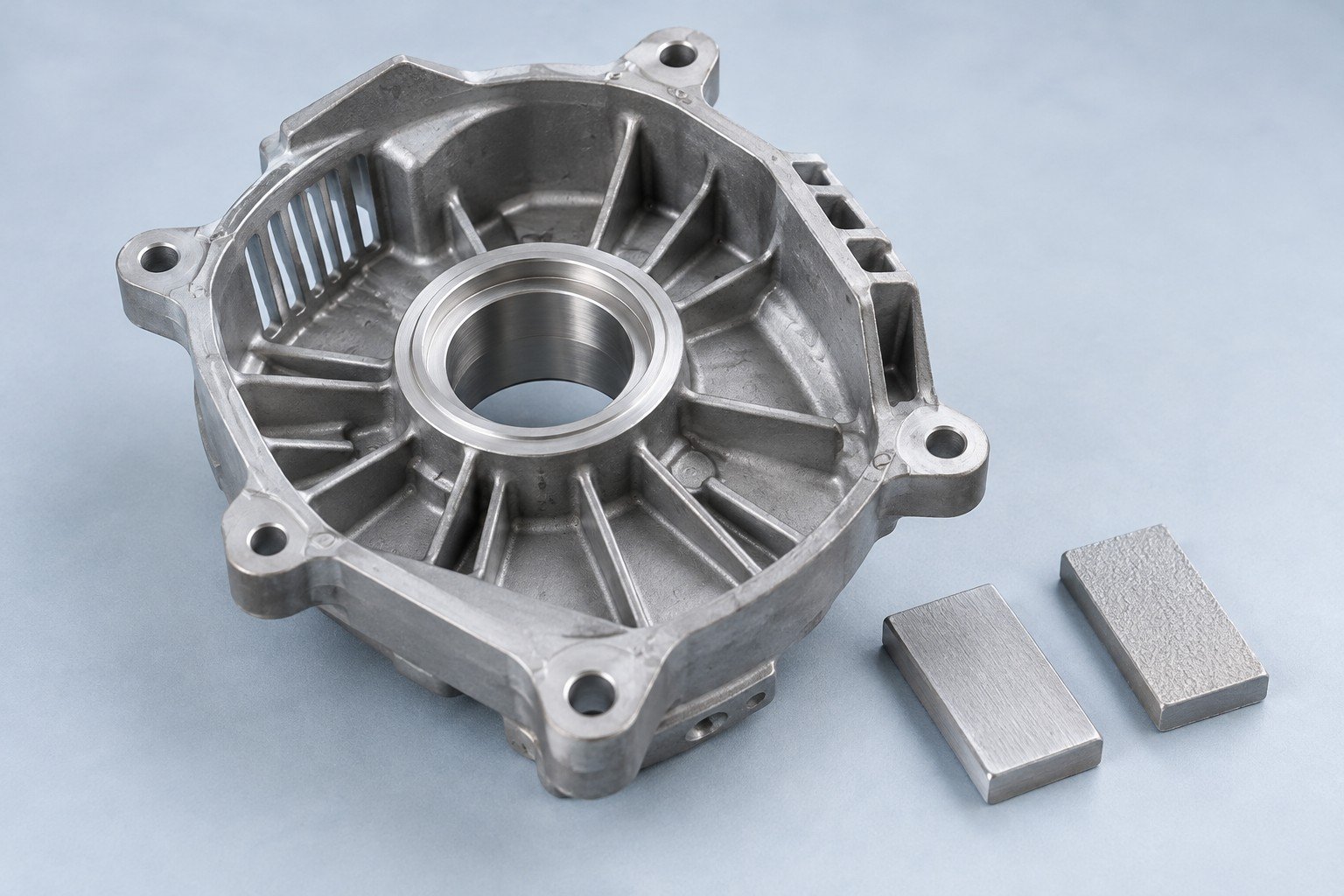
Plan aluminum die casting with secondary machining for your bores, threads and sealing faces.
| Your drawing | Datums, tolerances and machining symbols |
|---|---|
| Your allowance | Stock and access on machined features |
| Your check | Measurement method and support |
Part geometry and manufacturing scope are reviewed with your drawing.
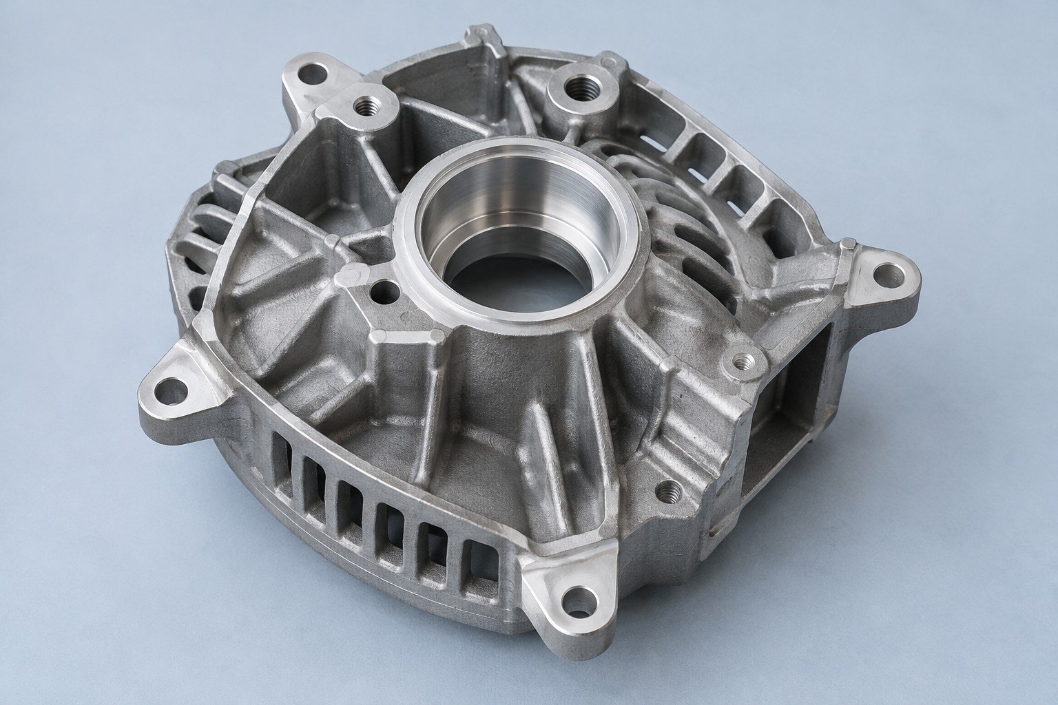
Agree dimensions, appearance and functional checks before the trial run.
| Your dimensions | Critical interfaces and measurement conditions |
|---|---|
| Your appearance | Finish sample and visible surface zones |
| Your function | Loads, leak conditions or assembly checks |
Part geometry and manufacturing scope are reviewed with your drawing.
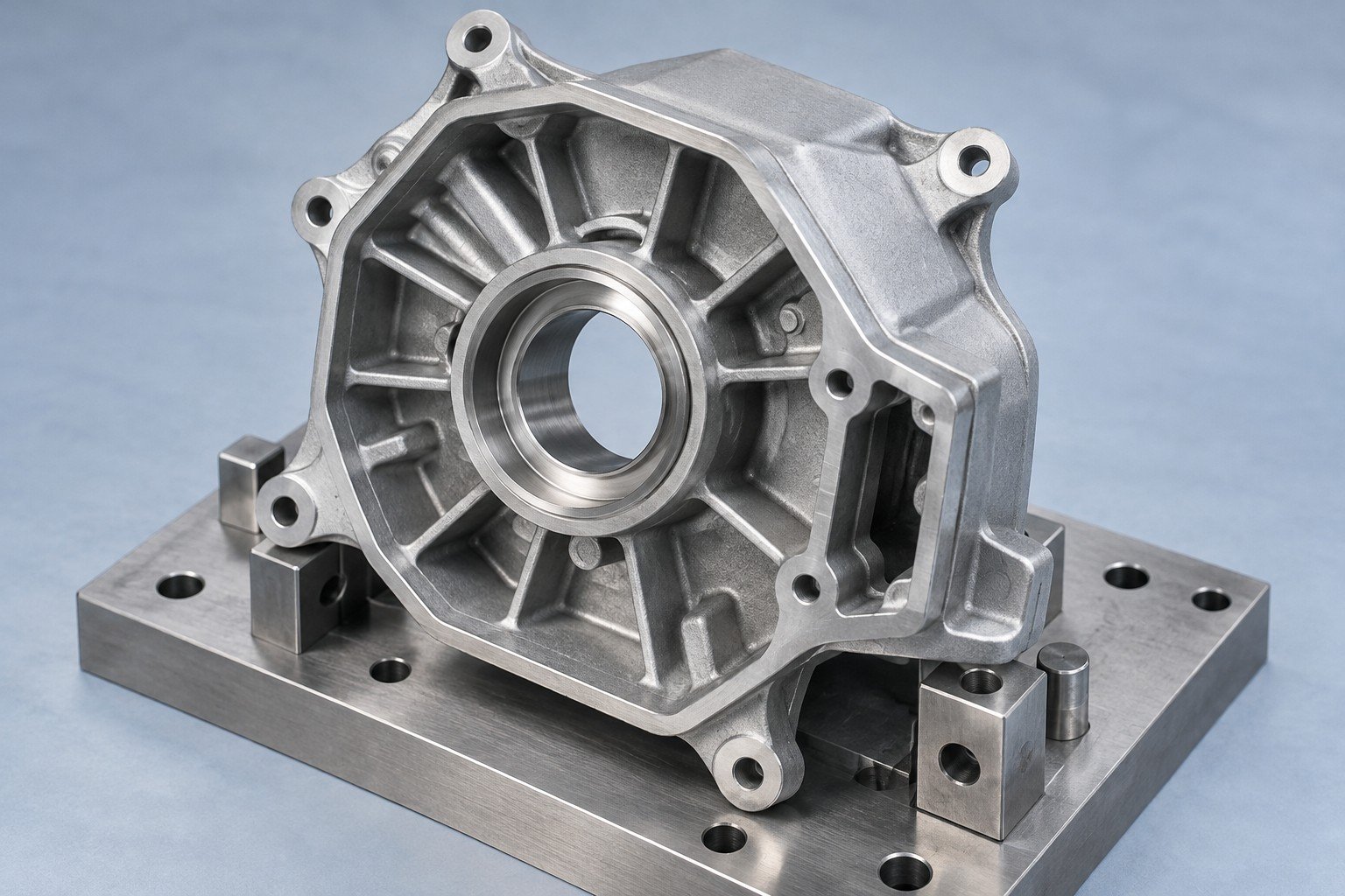
Share the load direction, mating components and fastener details.
| For your function | Joint loads and mating parts |
|---|---|
| For your fit | Fastener access and locating faces |
| For your supply | Quantity and required acceptance records |
Part geometry and manufacturing scope are reviewed with your drawing.
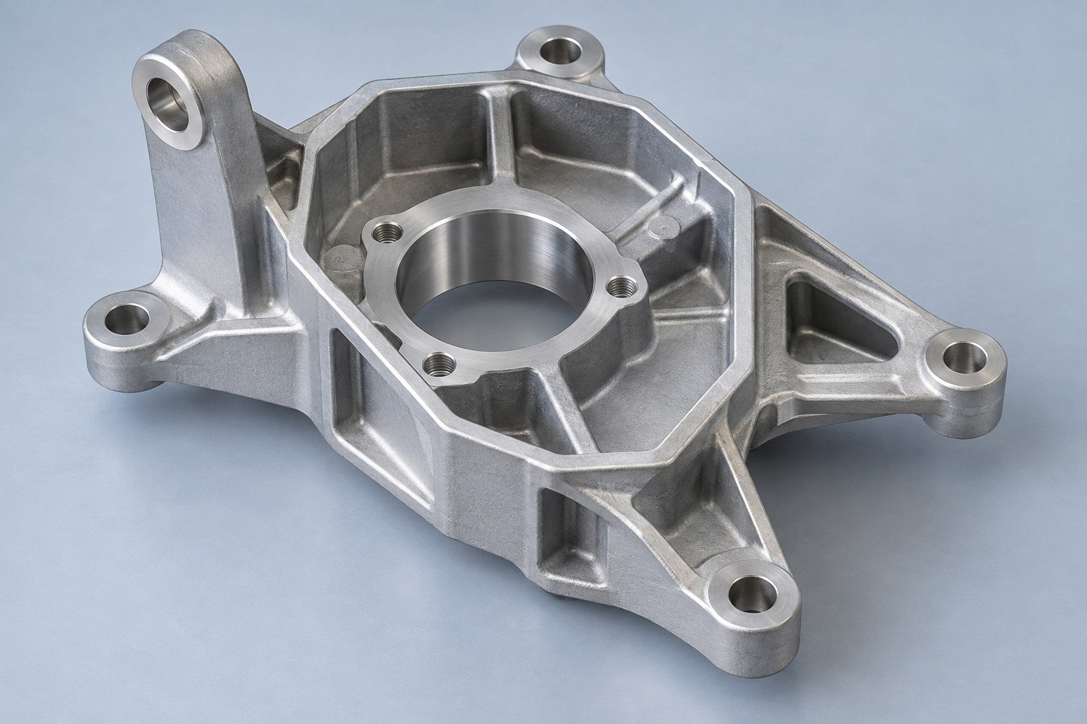
Compare aluminum die casting alloys with your corrosion, thermal, mechanical and finish requirements.
| Your specification | Grade, standard and required material records |
|---|---|
| Your environment | Temperature, fluids and exposure |
| Your finish | Surface sample, coating and masking |
Part geometry and manufacturing scope are reviewed with your drawing.
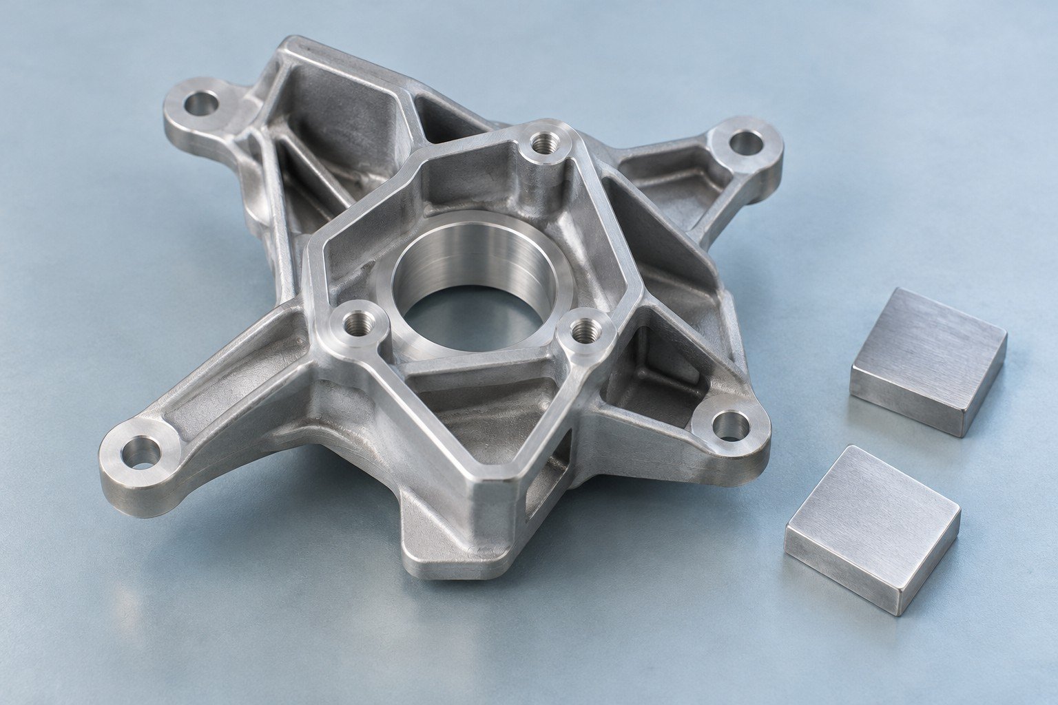
Plan aluminum die casting with secondary machining for your bores, threads and sealing faces.
| Your drawing | Datums, tolerances and machining symbols |
|---|---|
| Your allowance | Stock and access on machined features |
| Your check | Measurement method and support |
Part geometry and manufacturing scope are reviewed with your drawing.
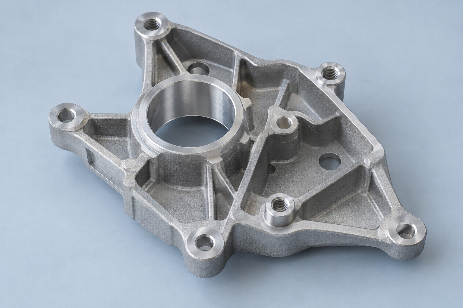
Agree dimensions, appearance and functional checks before the trial run.
| Your dimensions | Critical interfaces and measurement conditions |
|---|---|
| Your appearance | Finish sample and visible surface zones |
| Your function | Loads, leak conditions or assembly checks |
Part geometry and manufacturing scope are reviewed with your drawing.
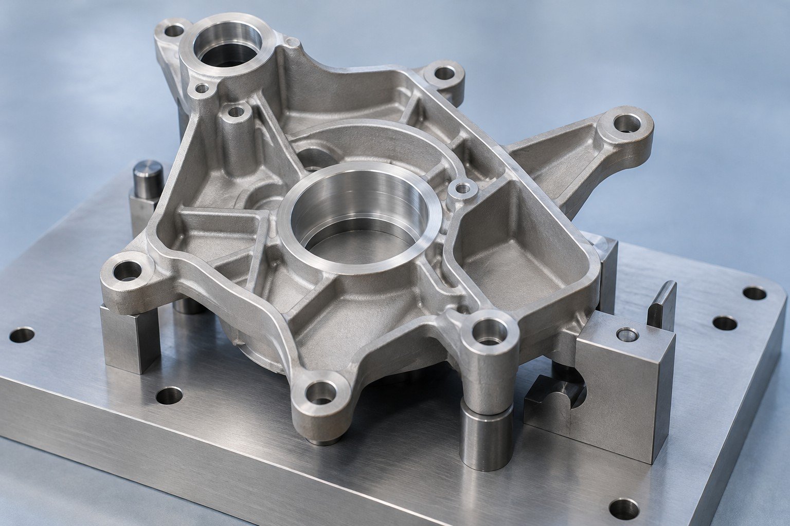
Compare aluminum die casting materials against your finish, geometry and service conditions.
| Grade | Starting point for your review | What to confirm |
|---|---|---|
| A380 | General housings | Corrosion protection and machining |
| ADC12 | Detailed geometry | Standard, composition and surface appearance |
| A360 | Pressure-related requirements | Trial, first article and agreed tests |
These are review starting points, not interchangeable specifications. Confirm grade, standard and lot records for your project.
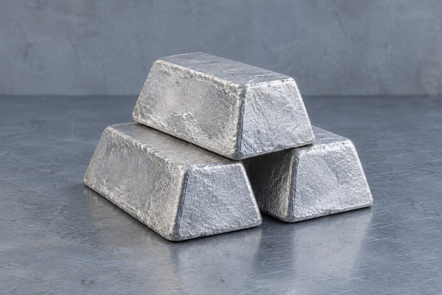
ALUMINUM DIE CASTING DESIGN GUIDELINES
Review the features that can add tool complexity, rework or assembly risk.
Review wall transitions, hollow bosses and rib intersections around your alloy and flow length.
Thick-to-thin changes
Fillets and local thickness
Core and fastener geometry
Alloy and flow length
Agree the method, units, fixture and inspection stage. Feasibility and acceptance limits are confirmed for your project.
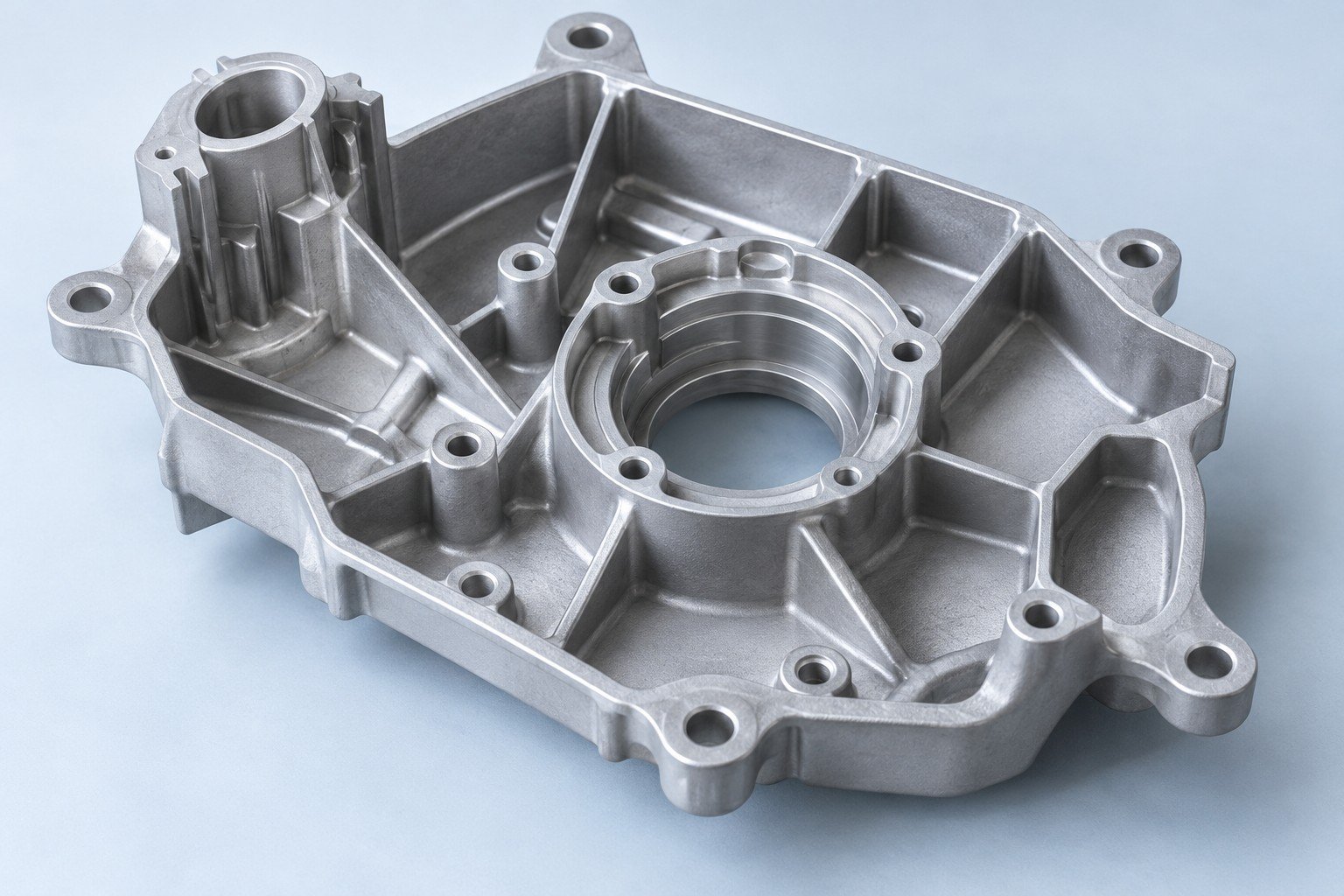
Agree aluminum die casting draft angle around depth, texture and release direction.
Parting line and movement
Feature depth and draft
Texture and finish
Undercuts and slides
Agree the method, units, fixture and inspection stage. Feasibility and acceptance limits are confirmed for your project.
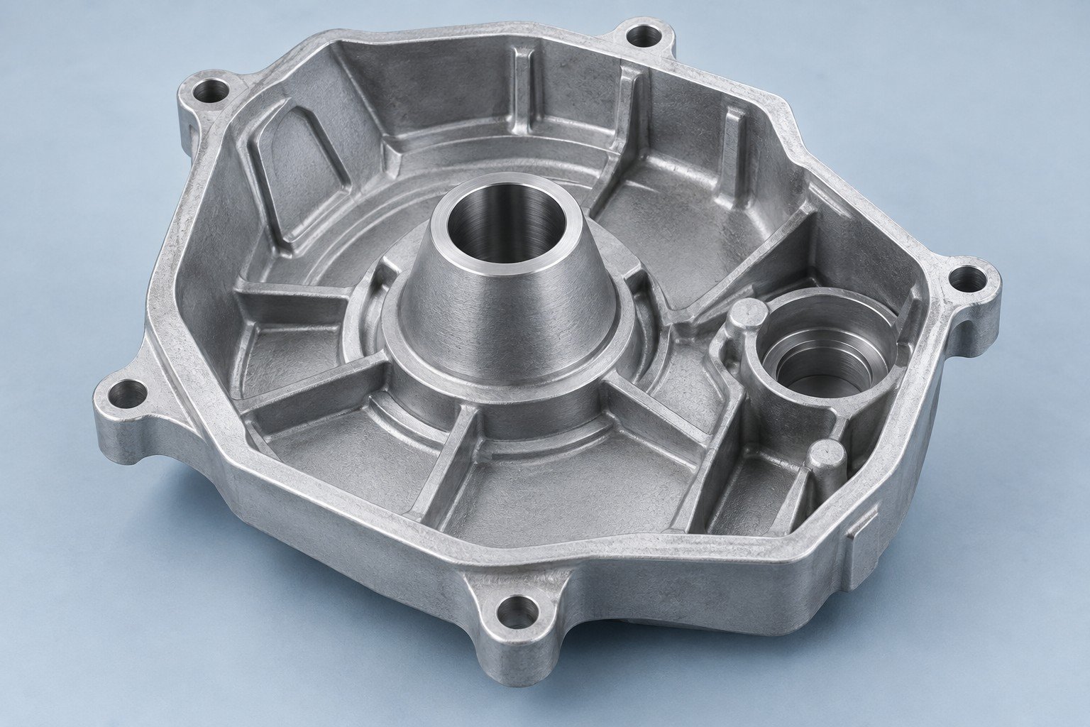
Review gate witnesses, venting and overflow access before the steel is cut.
Witness and trimming
Trapped-air risk
Access and clean-up
Analysis when specified
Agree the method, units, fixture and inspection stage. Feasibility and acceptance limits are confirmed for your project.
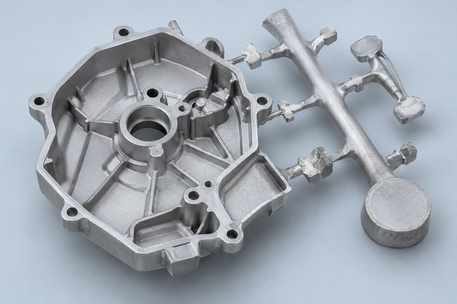
Mark datum faces and machining stock to protect your mating dimensions.
Locating and clamping
Feature allowance
Bores and threads
Support and conditions
Agree the method, units, fixture and inspection stage. Feasibility and acceptance limits are confirmed for your project.
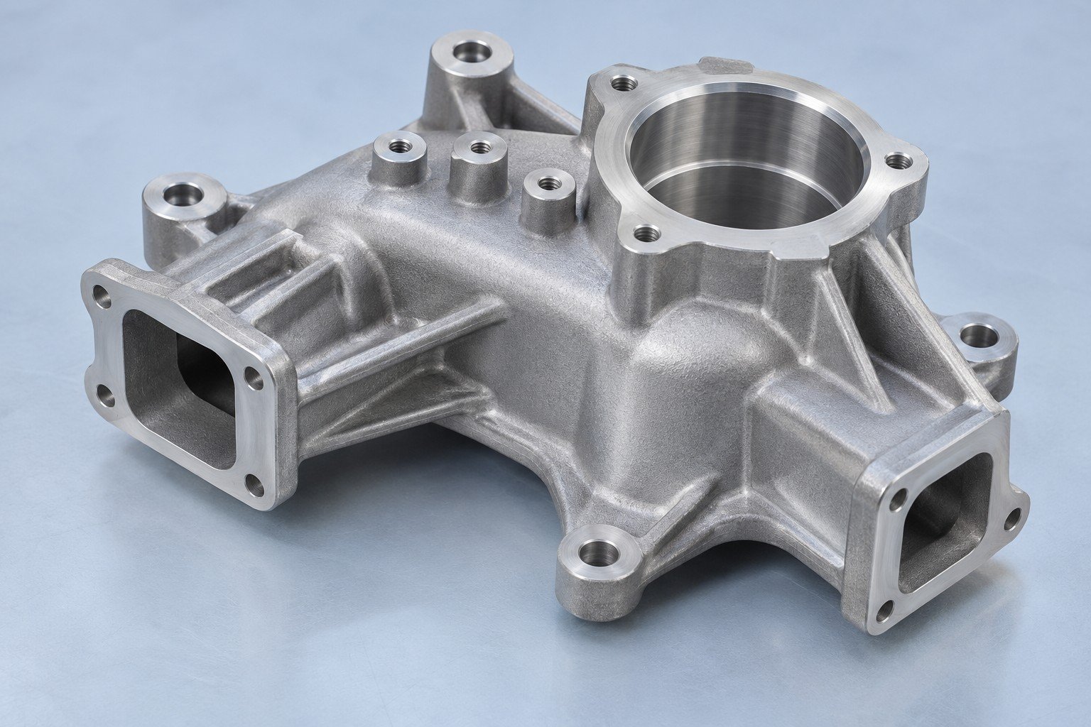
Assess aluminum die casting porosity around your machined walls and sealing faces.
Fluid or gas
Agreed pressure
Agreed duration
Acceptance limit
Agree the method, units, fixture and inspection stage. Feasibility and acceptance limits are confirmed for your project.
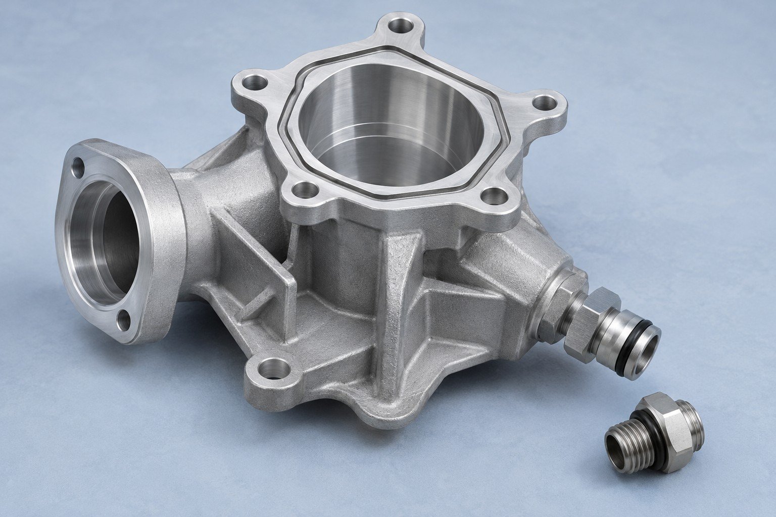
Review aluminum die casting surface finishing options around your alloy, appearance and coating thickness.
Approved finish sample
Threads and sealing faces
Thickness and fit
Finish suitability
Agree the method, units, fixture and inspection stage. Feasibility and acceptance limits are confirmed for your project.
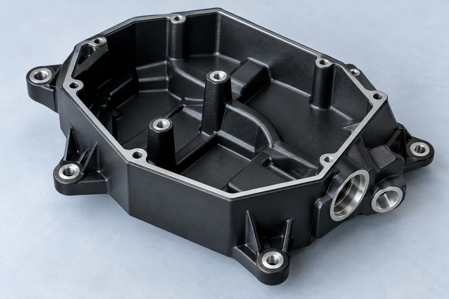
Define aluminum die casting tolerances by feature—not one number for the whole part.
| Feature state | What your drawing identifies | Review focus |
|---|---|---|
| As-cast | Walls, ribs and locating stock | Draw direction and parting lines |
| Finished | Bores, threads and seal faces | Datums, machining allowance and measurement |
Required values belong on your controlled drawing. Confirm feasibility before tooling.
Aluminum die casting with secondary machining keeps your cast geometry and final interfaces in one plan.
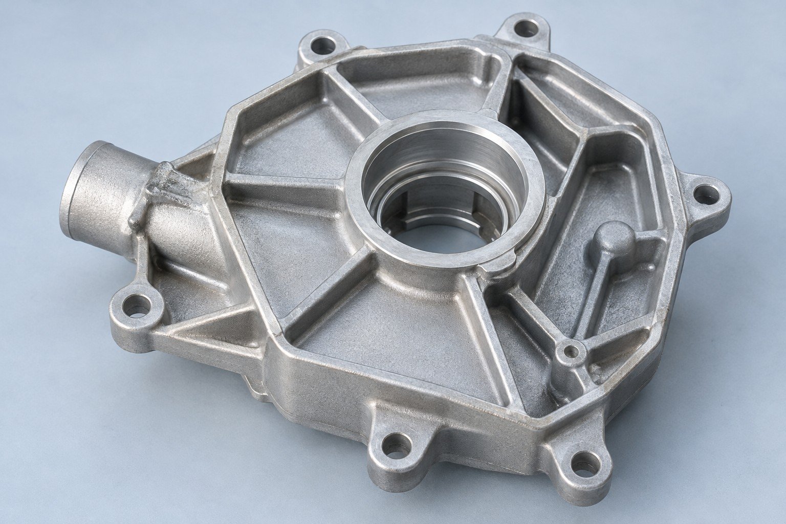
Casting geometry and gate clean-up
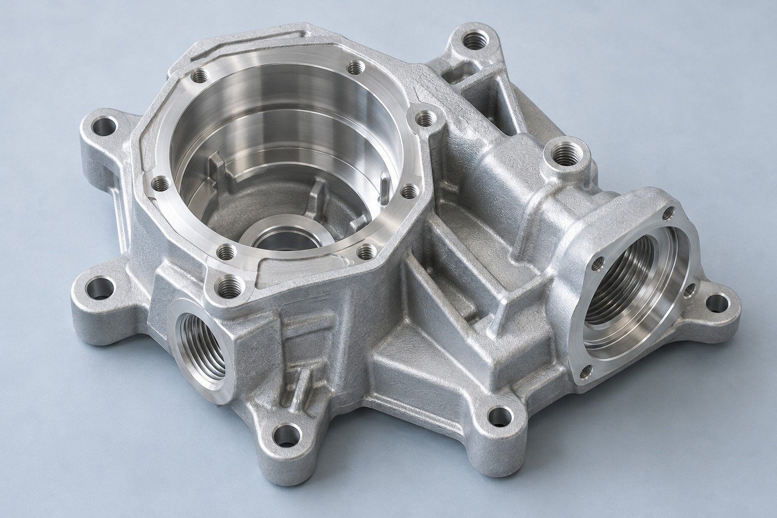
Bores, threads and sealing faces
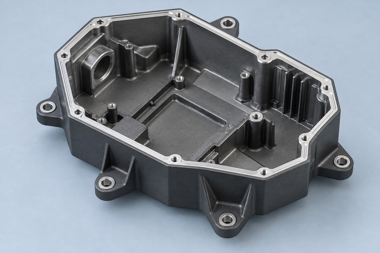
Masking, appearance and final checks
Secondary operations are included only when specified in your quotation.
CNC machining →Agree the records your team will use for release.
Confirm the alloy specification, incoming lot and records before the casting run.
Document scope, sampling and special tests are agreed in your quote.
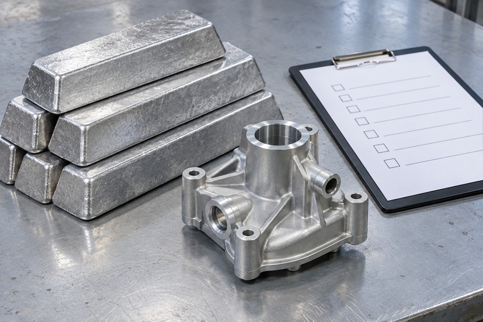
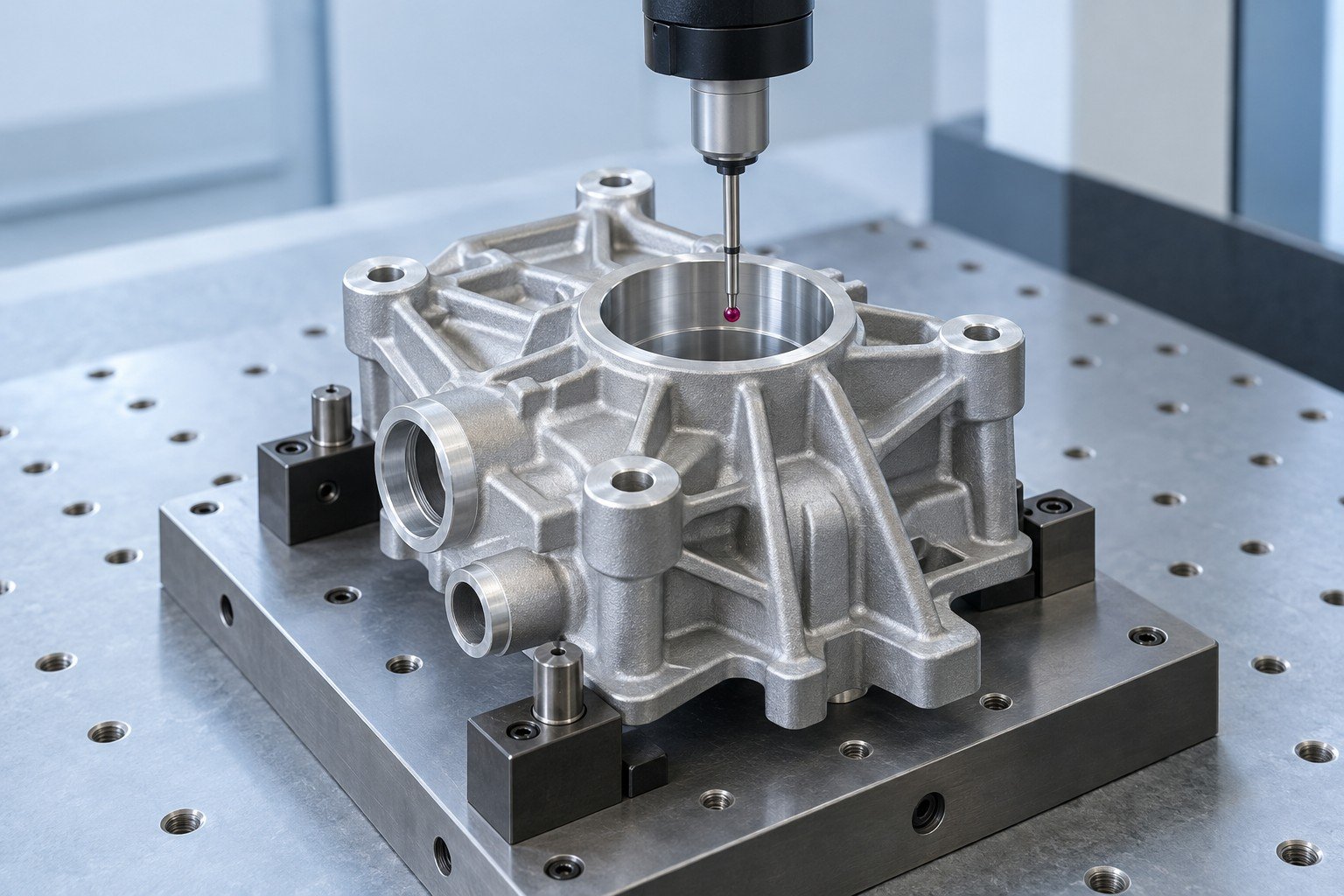
Review sample results, open issues and approval status before release.
Document scope, sampling and special tests are agreed in your quote.
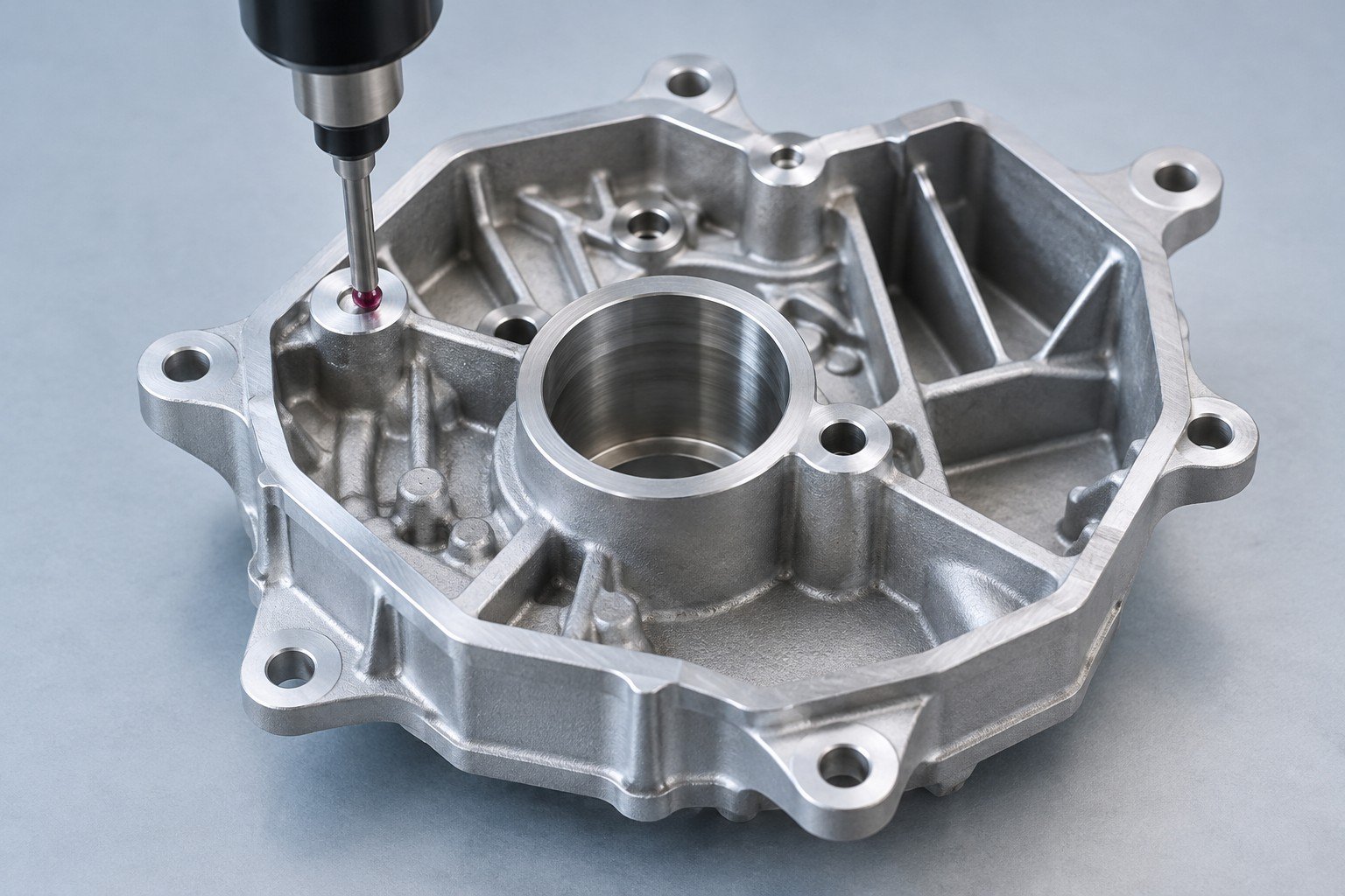
Agree sampling, critical features and actions when a check falls outside the limit.
Document scope, sampling and special tests are agreed in your quote.
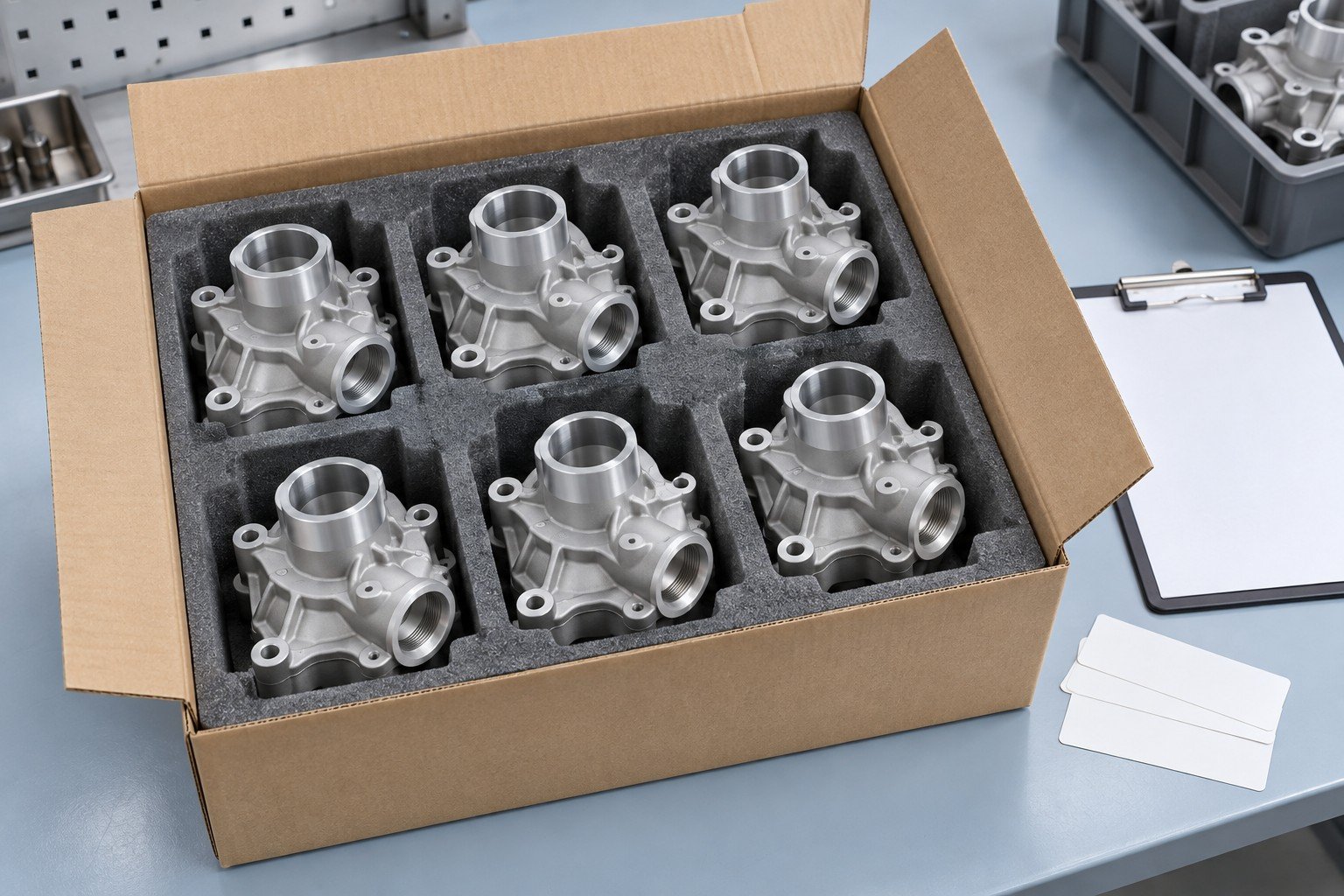
Review final checks, labels, part protection and shipment records before dispatch.
Document scope, sampling and special tests are agreed in your quote.
Separate aluminum die casting cost into tooling and recurring production items.
ILLUSTRATIVE RFQ QUANTITIES — NOT MINIMUM ORDERS
Pilot comparison
Initial production comparison
Higher-volume comparison
Tooling
Casting
CNC machining
Finishing
Inspection
Delivery
Replace these example quantities with your actual demand. Compare the same drawing revision, alloy and acceptance scope at every quantity.
For your aluminum die casting mold cost, confirm the separate commercial terms.
Who owns the tool and where it is stored.
Maintenance plan and expected tool life.
How design changes are approved and charged.
Conditions for repeat orders or tool transfer.
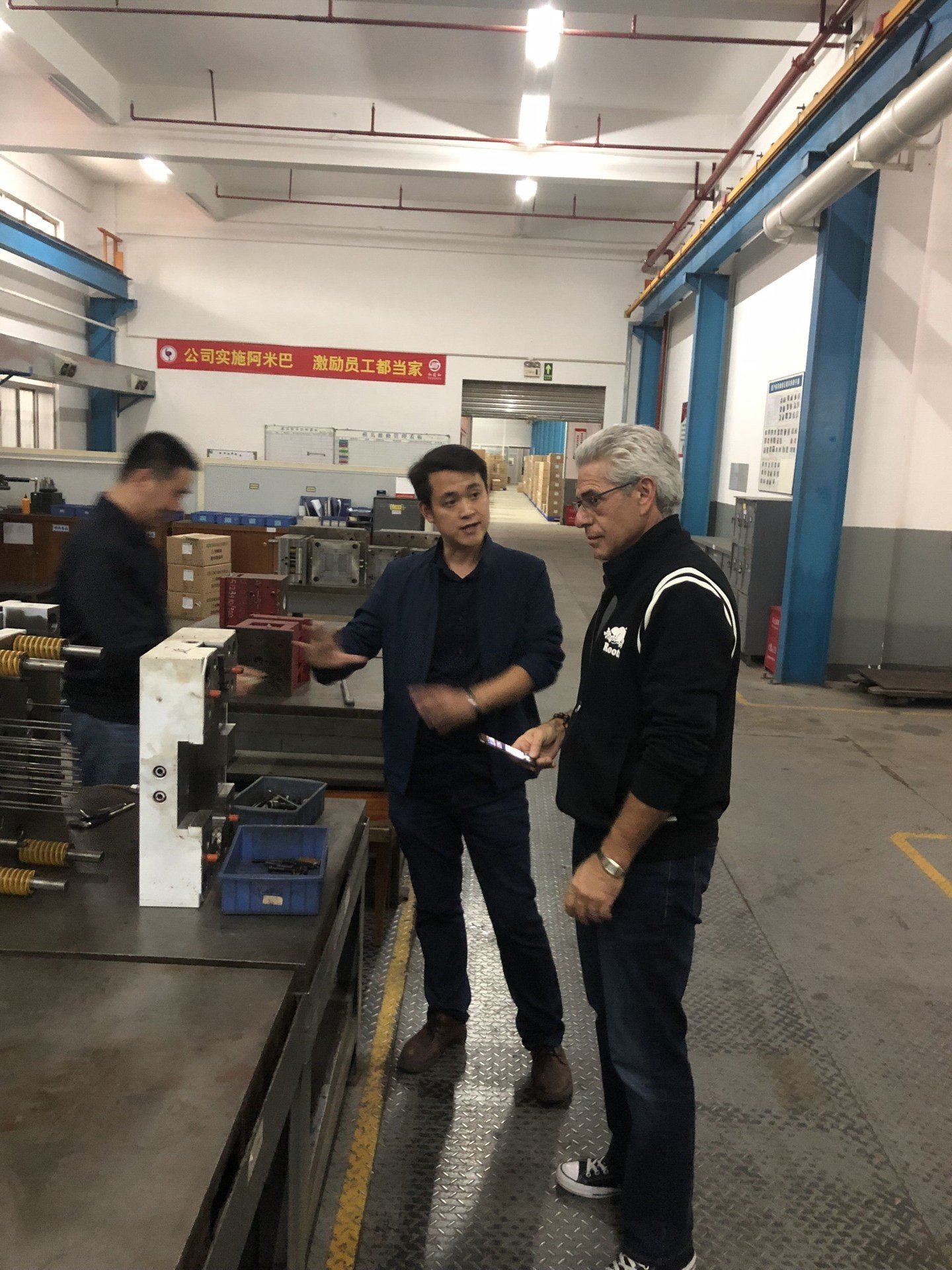
Coordinate drawing review, sample decisions and delivery with your project contact. Manufacturing scope and location are confirmed in your quotation.
Share the details needed for a scoped tooling and part quotation.
Confirm ownership, location, maintenance, design-change approval and transfer conditions in your project quotation. Tooling cost and recurring part price are separate items.
Suitability depends on the grade and appearance target. Silicon-rich cast alloys may produce uneven cosmetic results; review a finish sample and alternative coatings before specifying the result.
The economic quantity depends on tooling investment, geometry and your demand. Request a comparison for your actual trial, first order and repeat quantities; the example quantities on this page are not minimum orders.
Confirm separate milestones for DFM approval, tool build, trial, revisions and sample approval. Production and shipping follow the agreed release plan; a delivery date is confirmed in your project quote.
Use as-cast geometry where it meets your drawing and plan machining for critical interfaces that need it. Mark datums, bores, threads and sealing faces so tolerance and inspection scope can be reviewed feature by feature.