3-Axis Milling
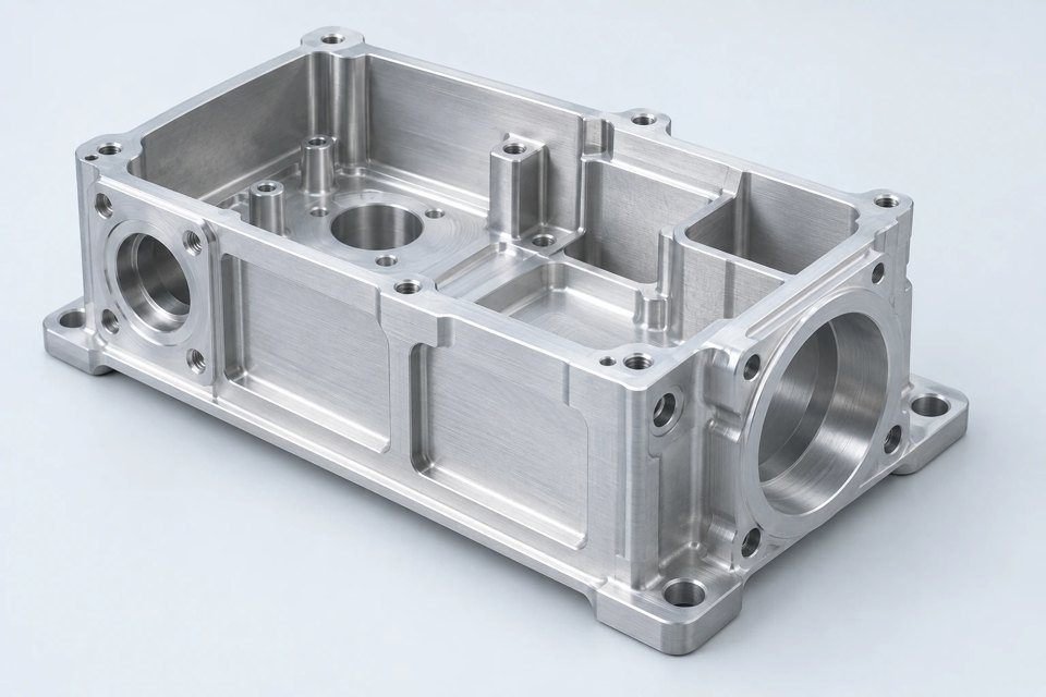
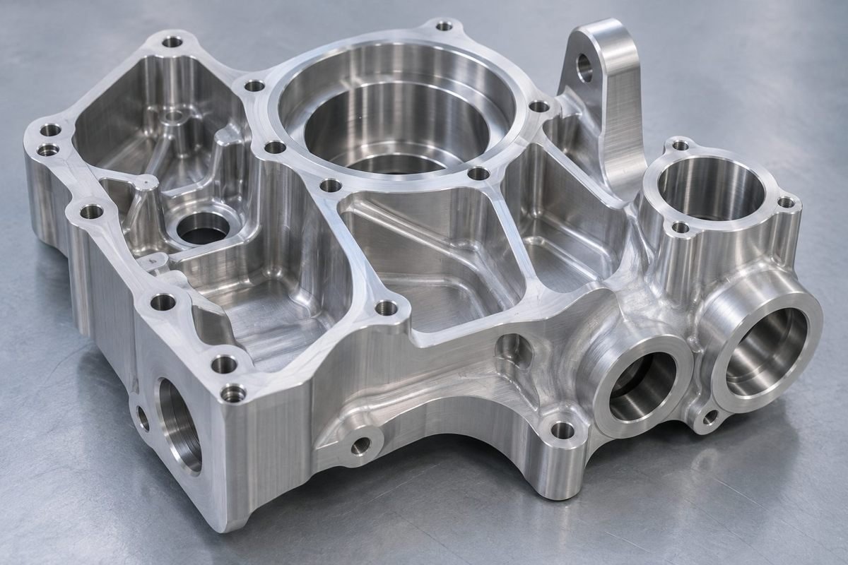
For your accessible pockets, flat faces and mounting features.
- Prismatic components
- Review each setup
- Practical tool access
Core manufacturing processes for your prototypes, low-volume and repeat production.
Advanced manufacturing and engineering support for your complex, tight-tolerance parts.
Plan inspection, documentation and delivery around your production program.
Choose air- or liquid-cooling components around your thermal and mechanical requirements.
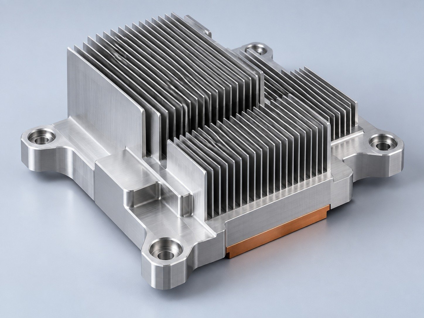
Manufacturing support for your cold plates, manifolds and cooling assemblies.
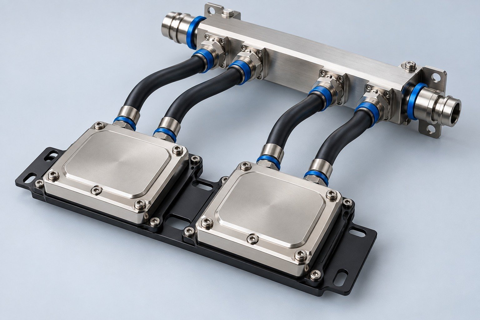
Find components for your power electronics, energy, laser and telecom application.
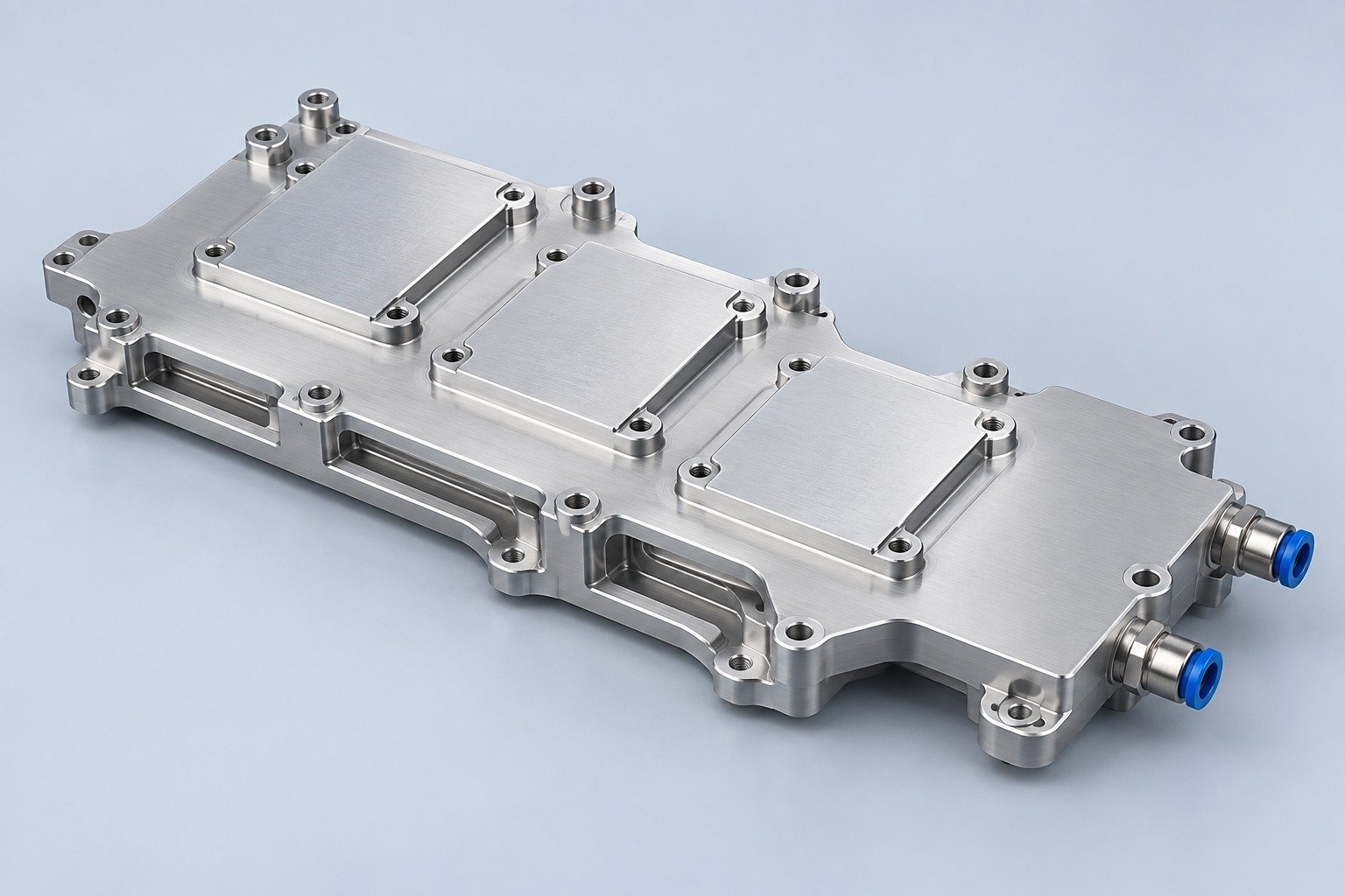
Components for your electronic systems.
Start with your functional and quality requirements.
Build around your operating environment.
Review grade, temper and finish for your metal parts.
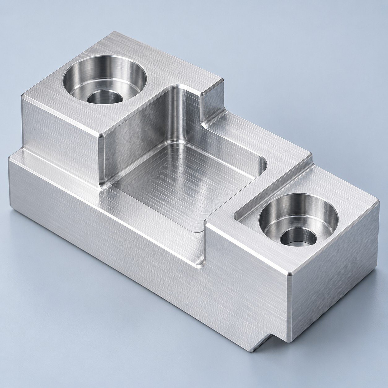 AluminumStrength, weight and machining
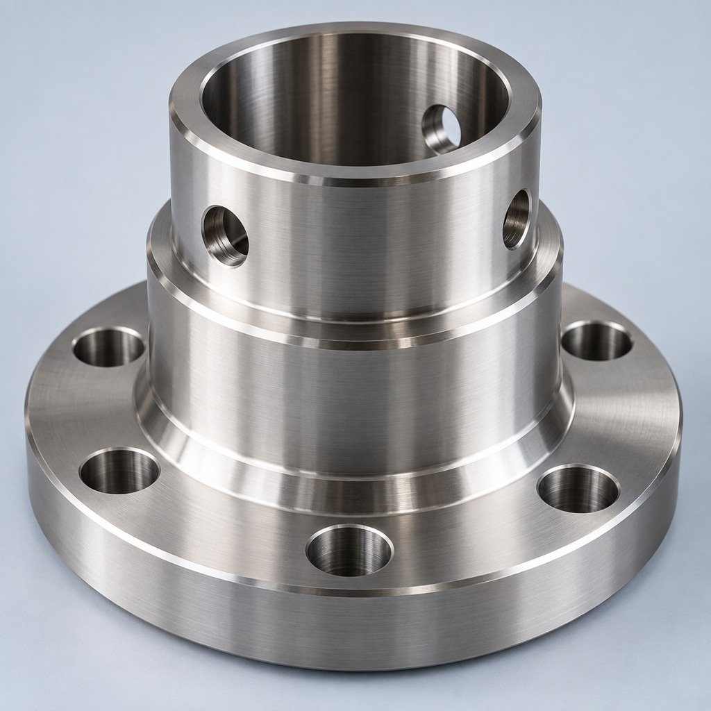 Stainless SteelCorrosion and finish requirements
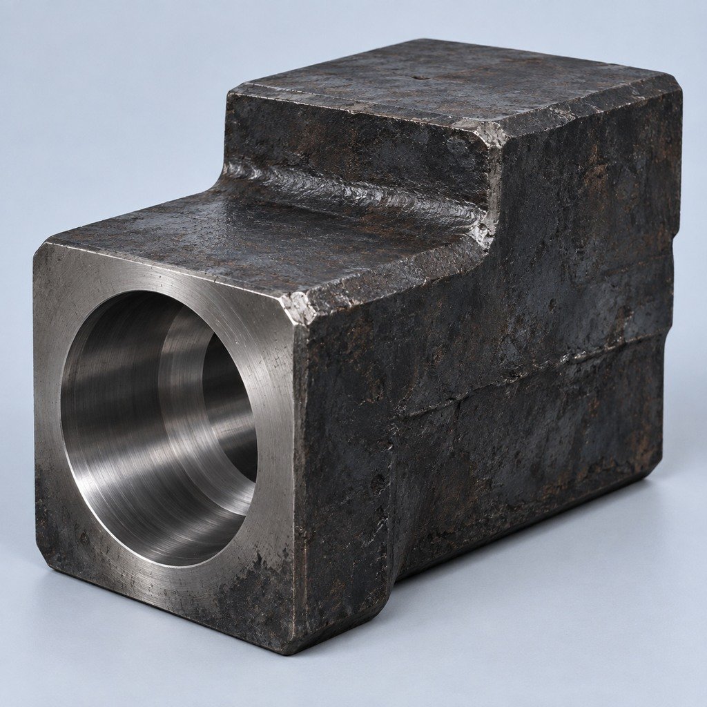 Carbon & Alloy SteelDiscuss grade and heat treatment
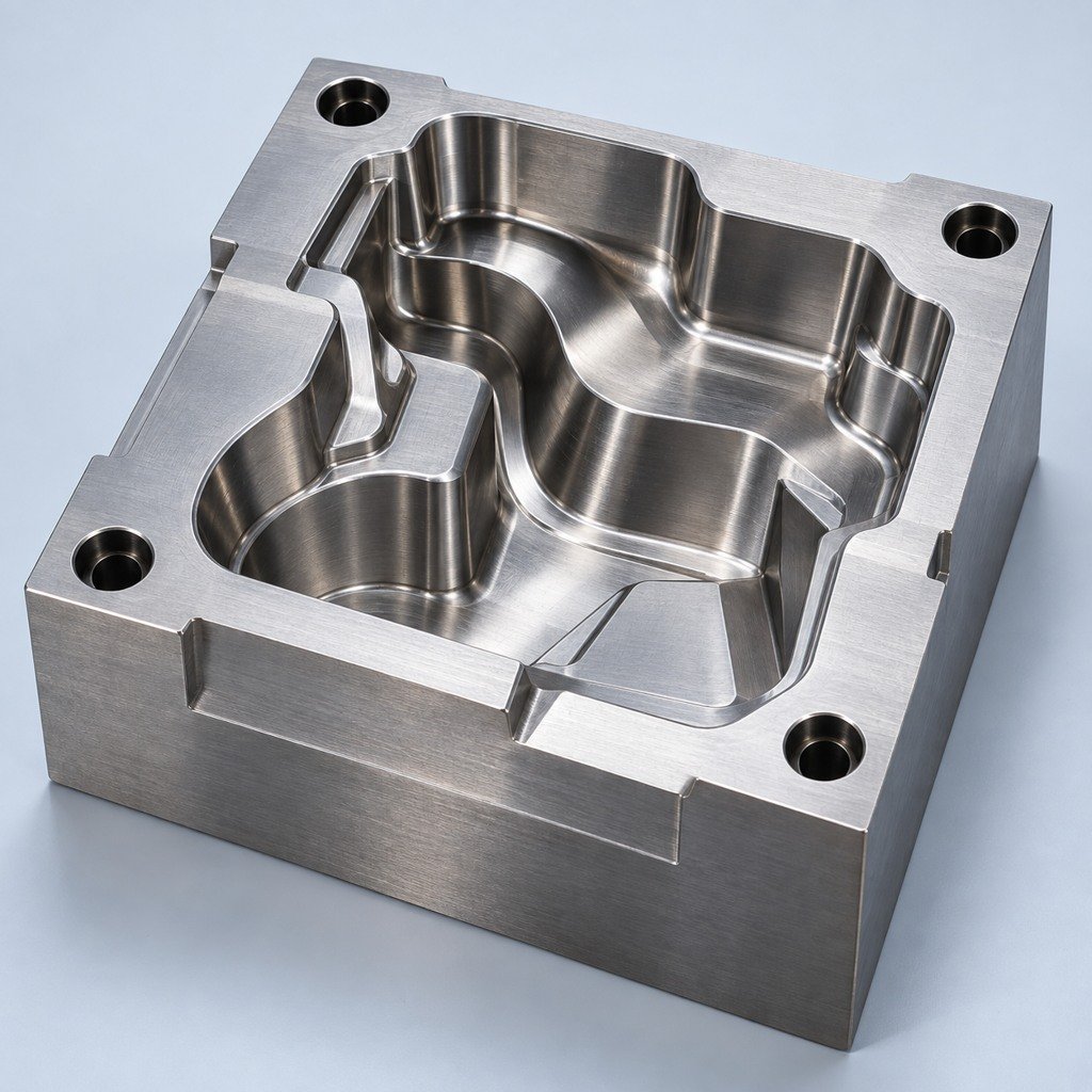 Tool SteelDiscuss tooling and wear needs
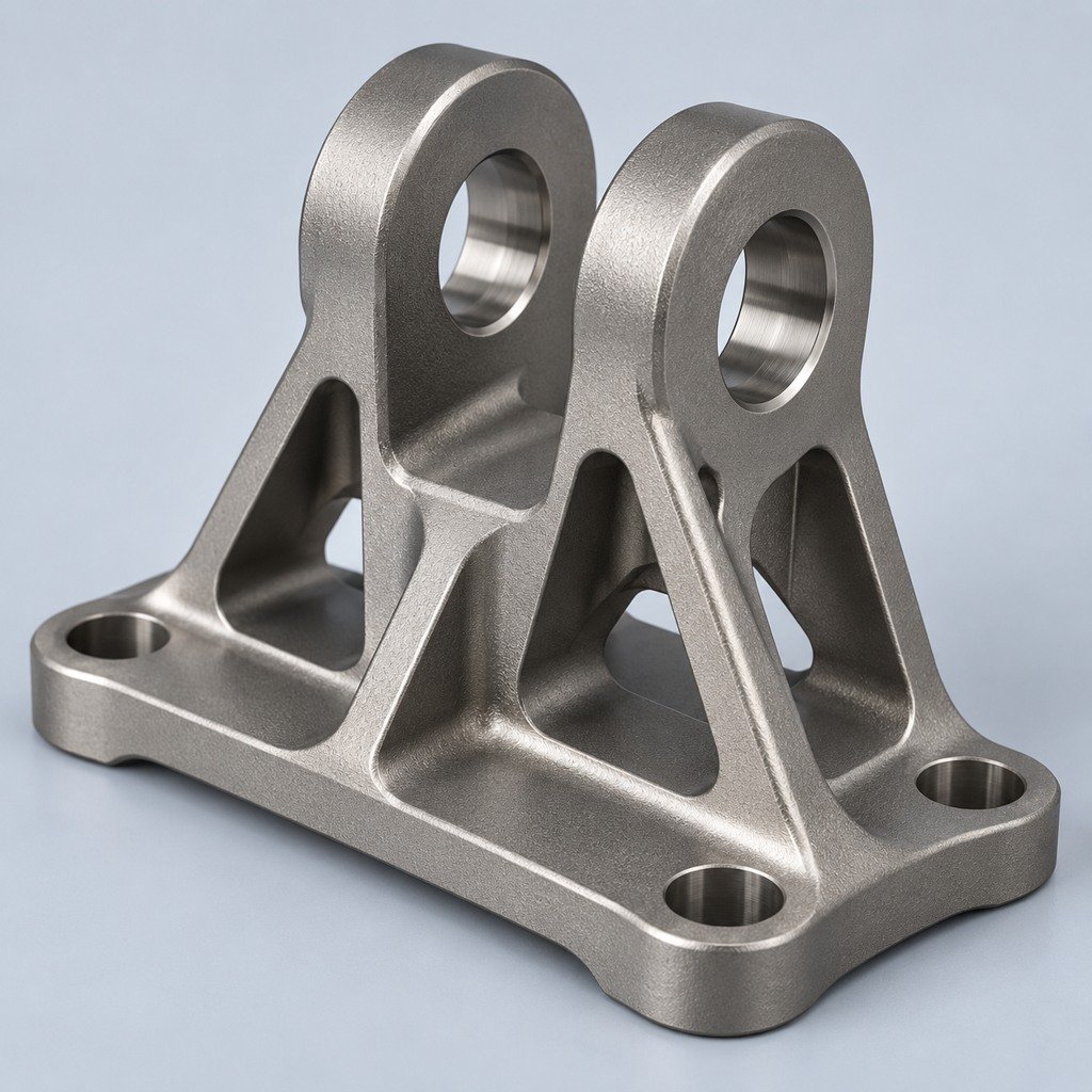 TitaniumReview grade and part geometry
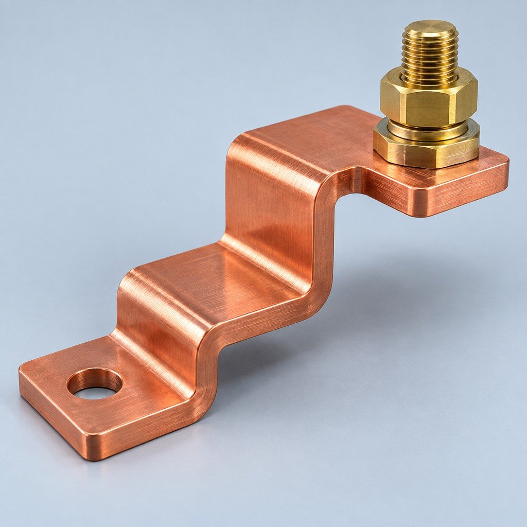 Copper & BrassDiscuss conductivity and machining
Match your polymer to function, process and environment.
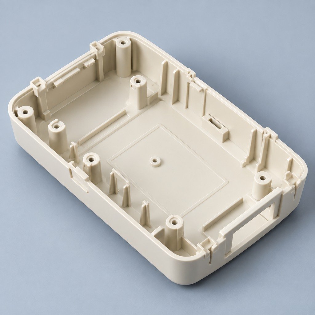 ABSReview enclosure and molding needs
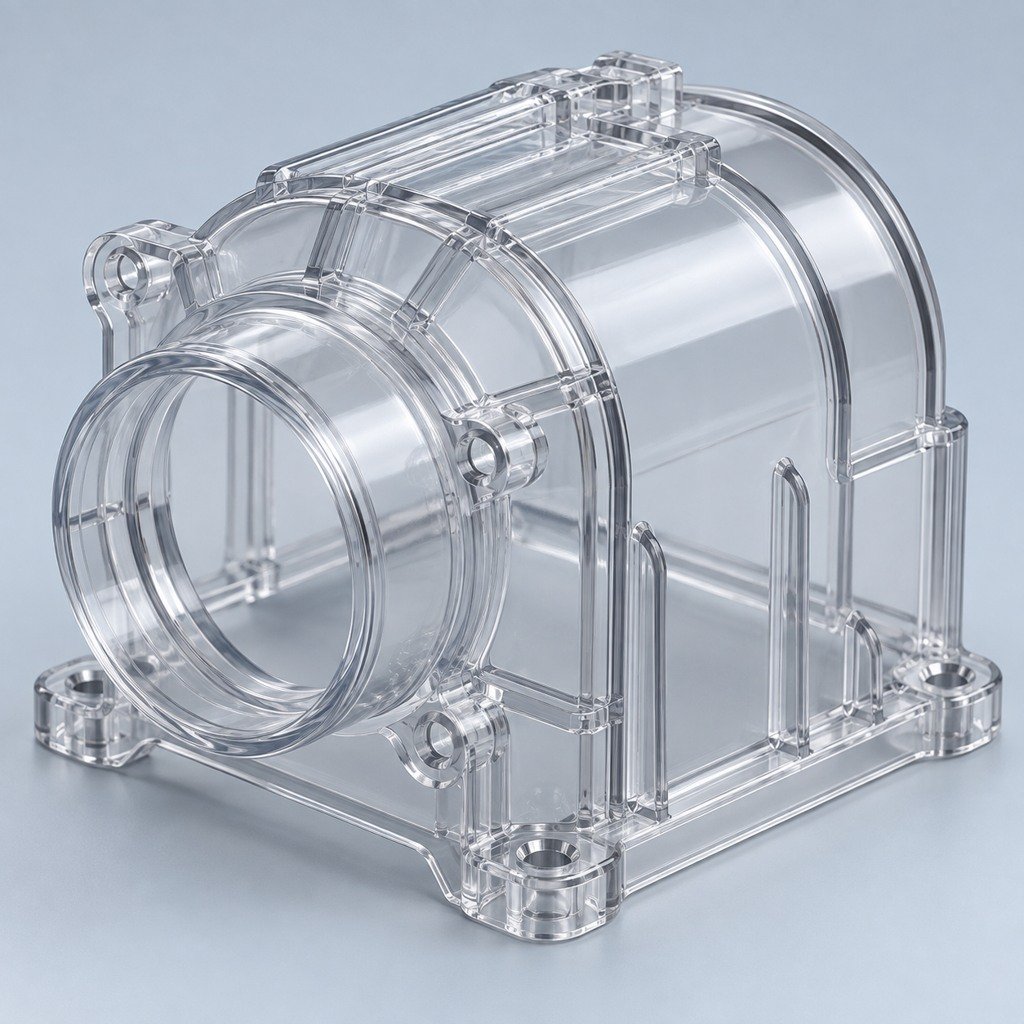 Polycarbonate (PC)Discuss clarity and impact needs
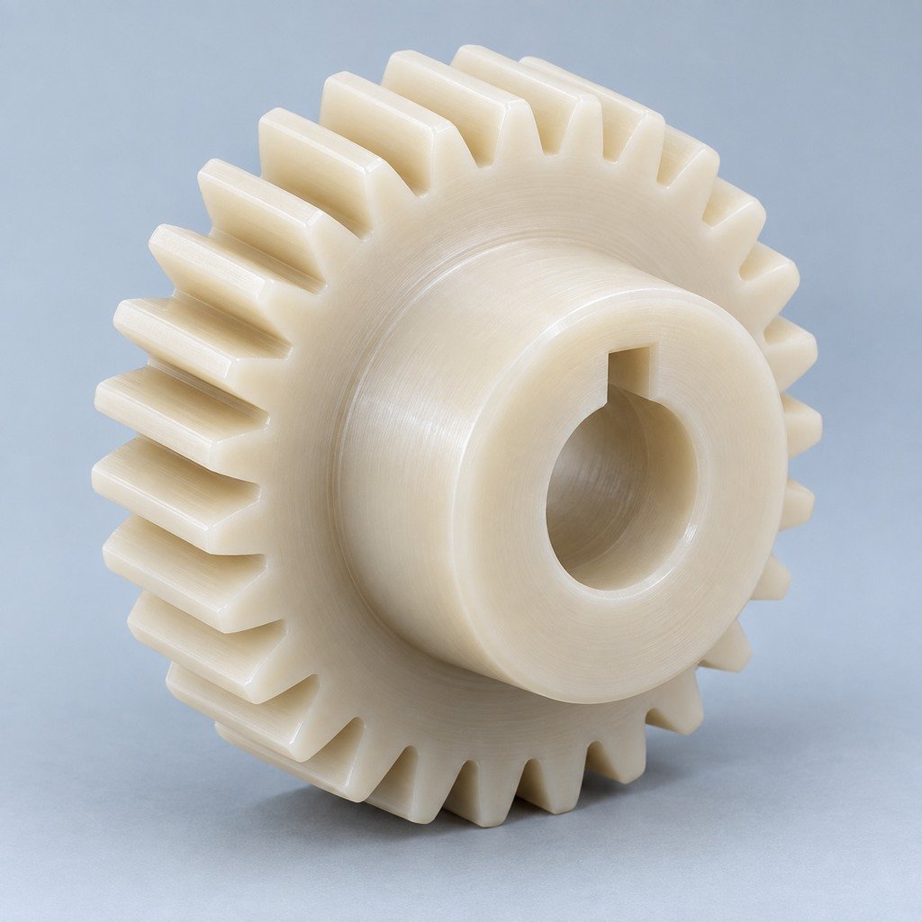 Nylon (PA)Review moisture and wear conditions
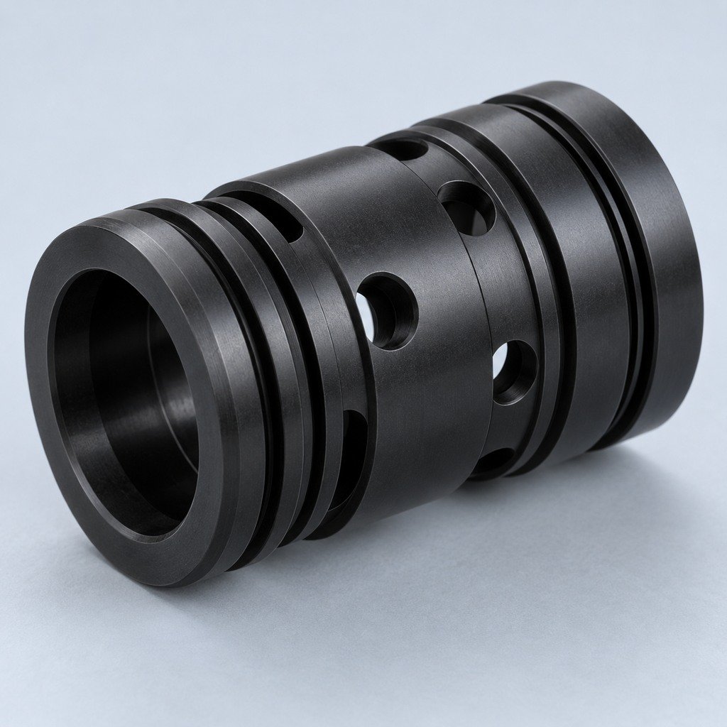 POM / AcetalReview fit and sliding features
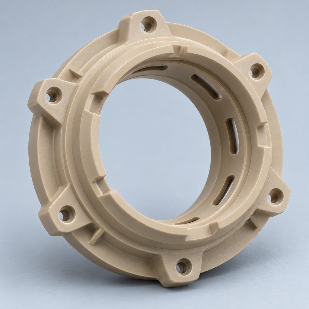 PEEKDiscuss operating conditions
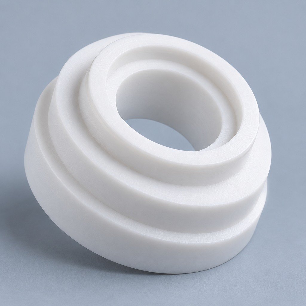 PTFEReview friction and chemical exposure
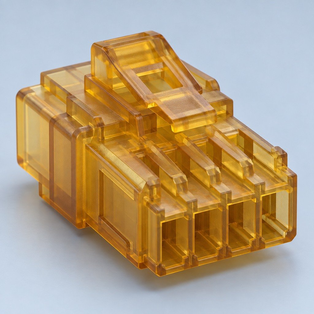 ULTEM / PEIDiscuss thermal and electrical needs
Confirm grade availability and application requirements.
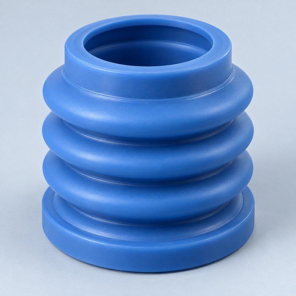 Silicone / LSRDiscuss flexible component needs
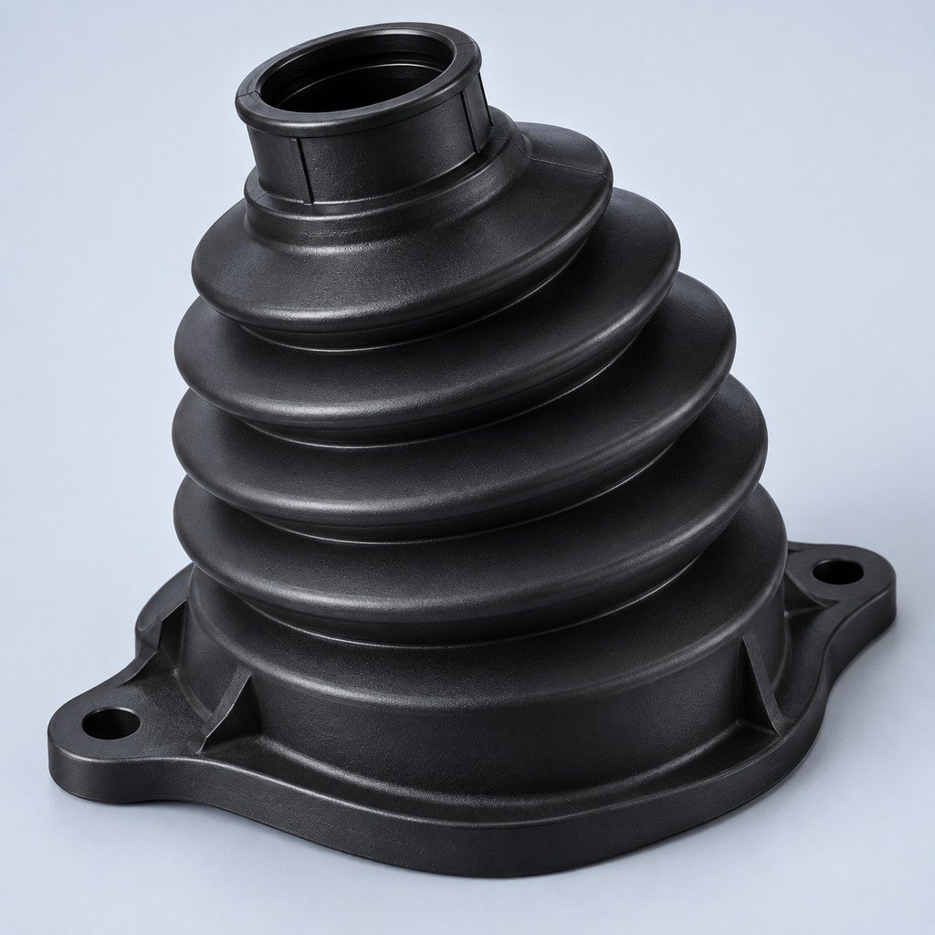 TPU / TPEReview flexibility and processing
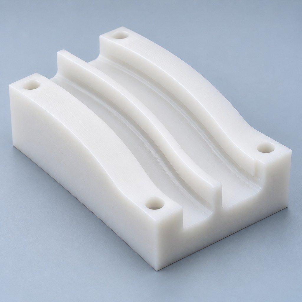 UHMW-PEDiscuss sliding and wear needs
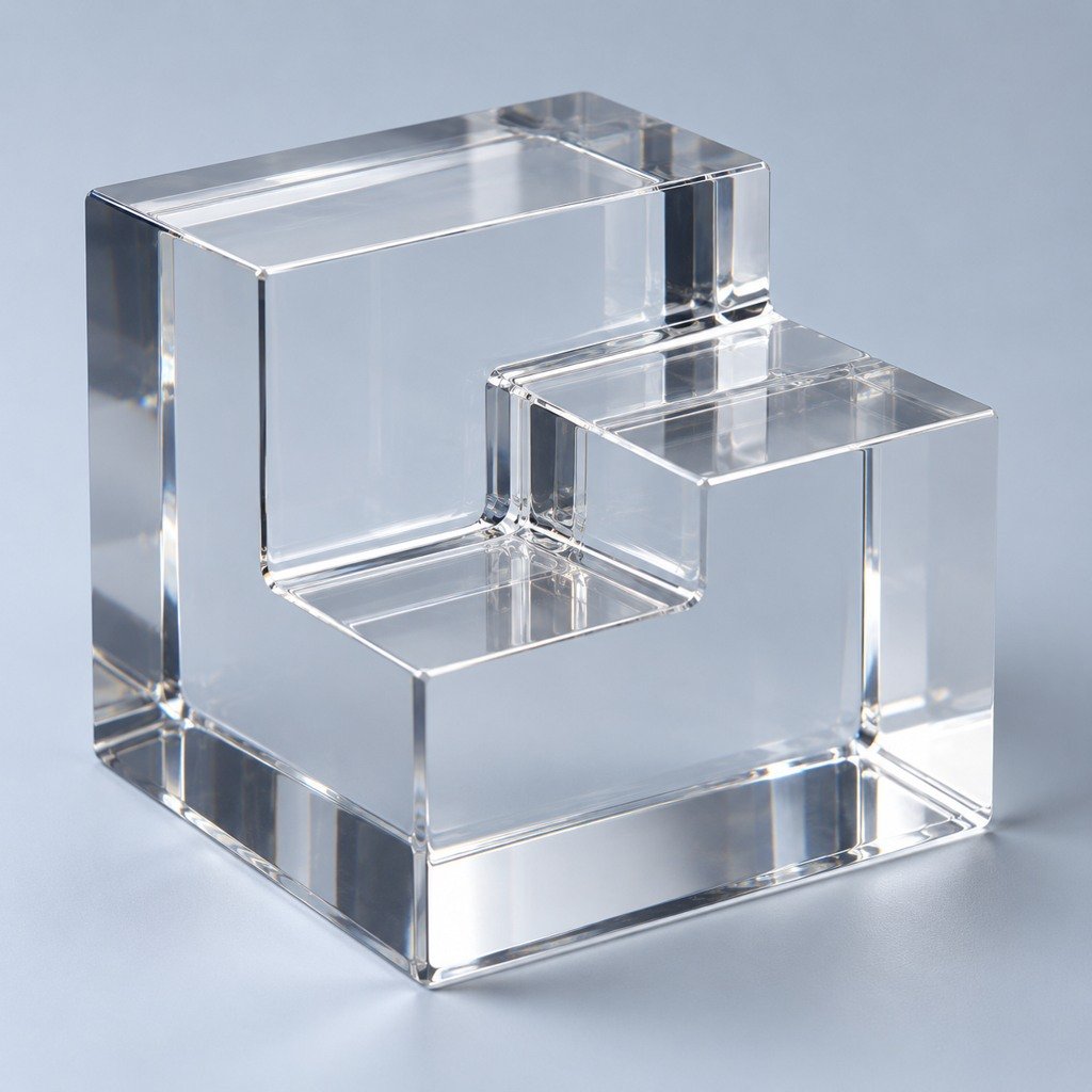 Acrylic / PMMAReview optical and cosmetic needs
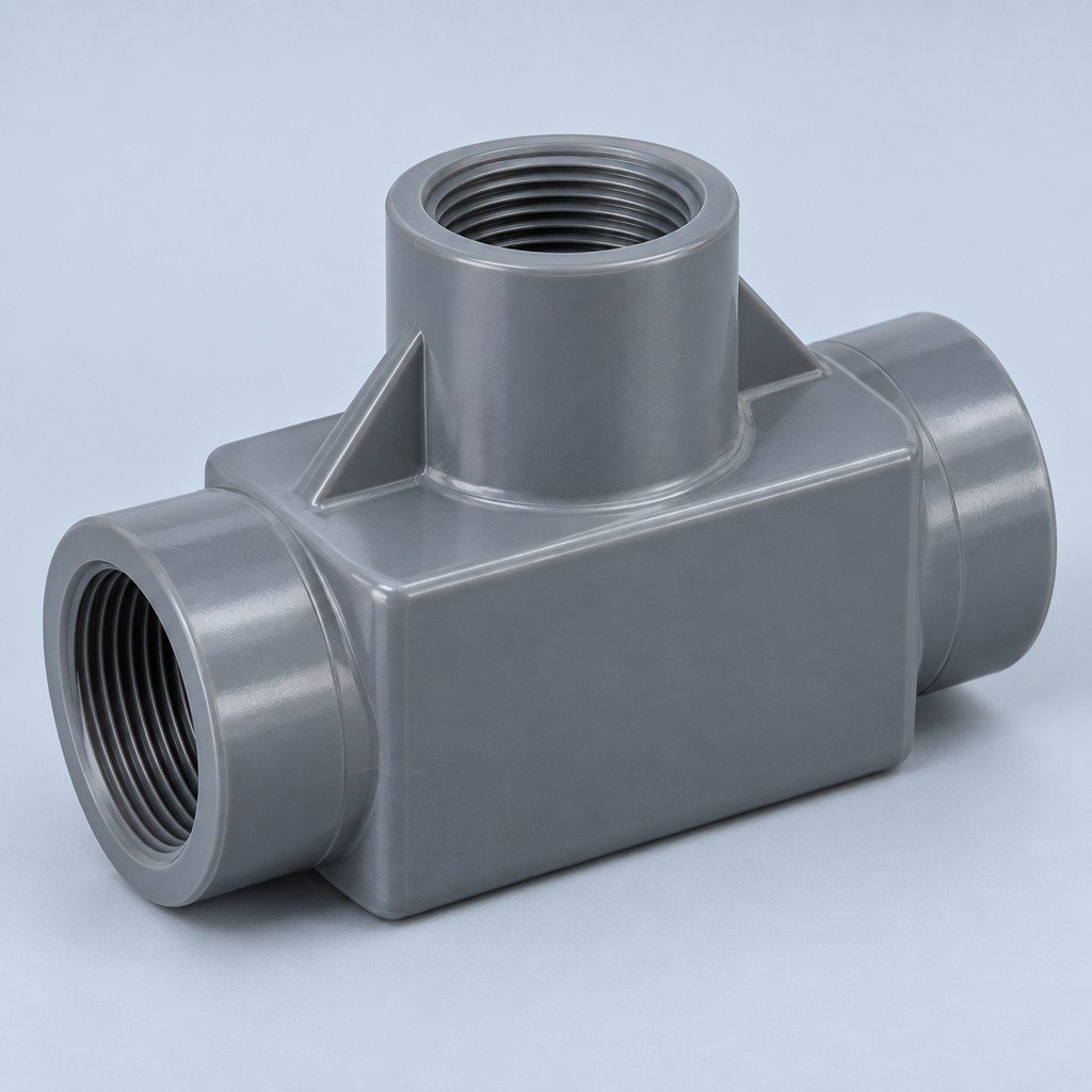 PVCDiscuss chemical exposure and grade
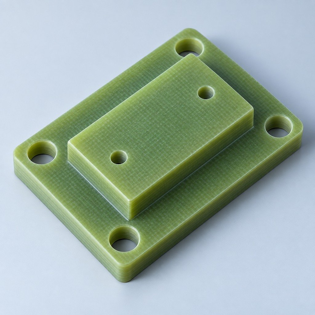 G10 / FR4Review insulation and laminate needs
Practical guidance for your part geometry and material decisions.
Prepare your process, budget and sourcing questions.
Build your knowledge before production.
Learn who we are and how we operate.
Find our U.S. support team or start a conversation.
CNC MILLING SERVICES
Turn your CAD into parts that fit your assembly.
Choose a reviewed 3-axis, 4-axis or 5-axis milling route for your metal and engineering plastic parts. Resolve tool access, material and inspection requirements before your prototype or production order.
Send your 3D CAD, controlled drawing, material and quantity.
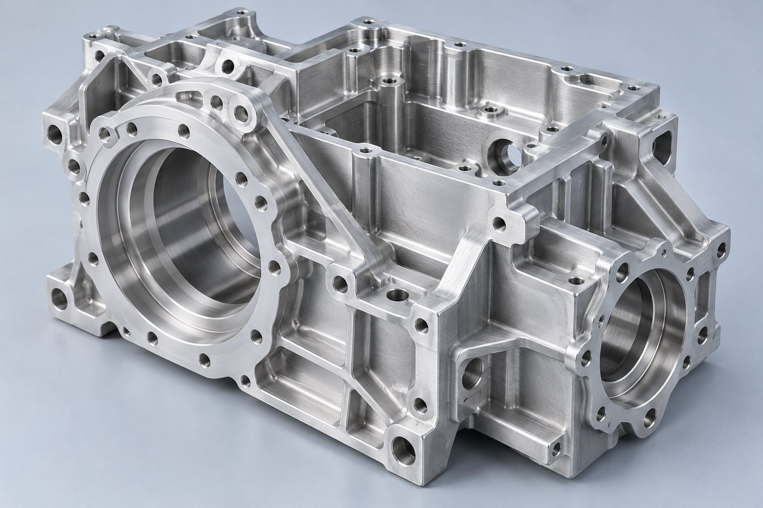
CNC MILLING OVERVIEW
Protect the features that matter to your assembly. Review your drawing, material and finish together, so machining decisions support your final use.
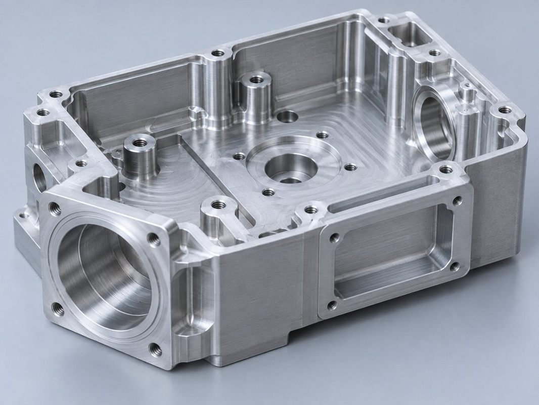
CHOOSE YOUR MILLING STRATEGY
Compare access, setup count and inspection needs before deciding how your part should be made.
For your accessible pockets, flat faces and mounting features.
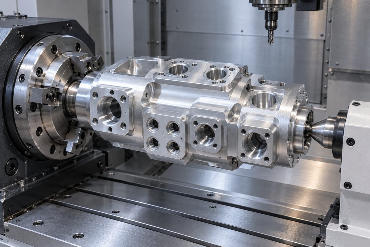
Index your part to reach features around multiple sides.
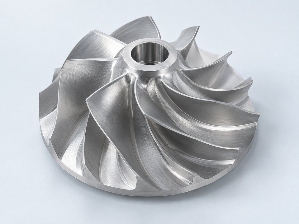
Reach your angled features and complex contoured surfaces.

Check your fit and function before committing to production.
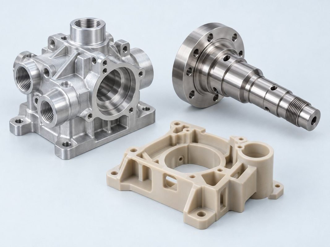
Keep your approved revision and requirements connected.
CNC MILLING DFM ANALYSIS
Resolve machining constraints while your design is still easy to change. Select a topic to review the decisions that affect your part.
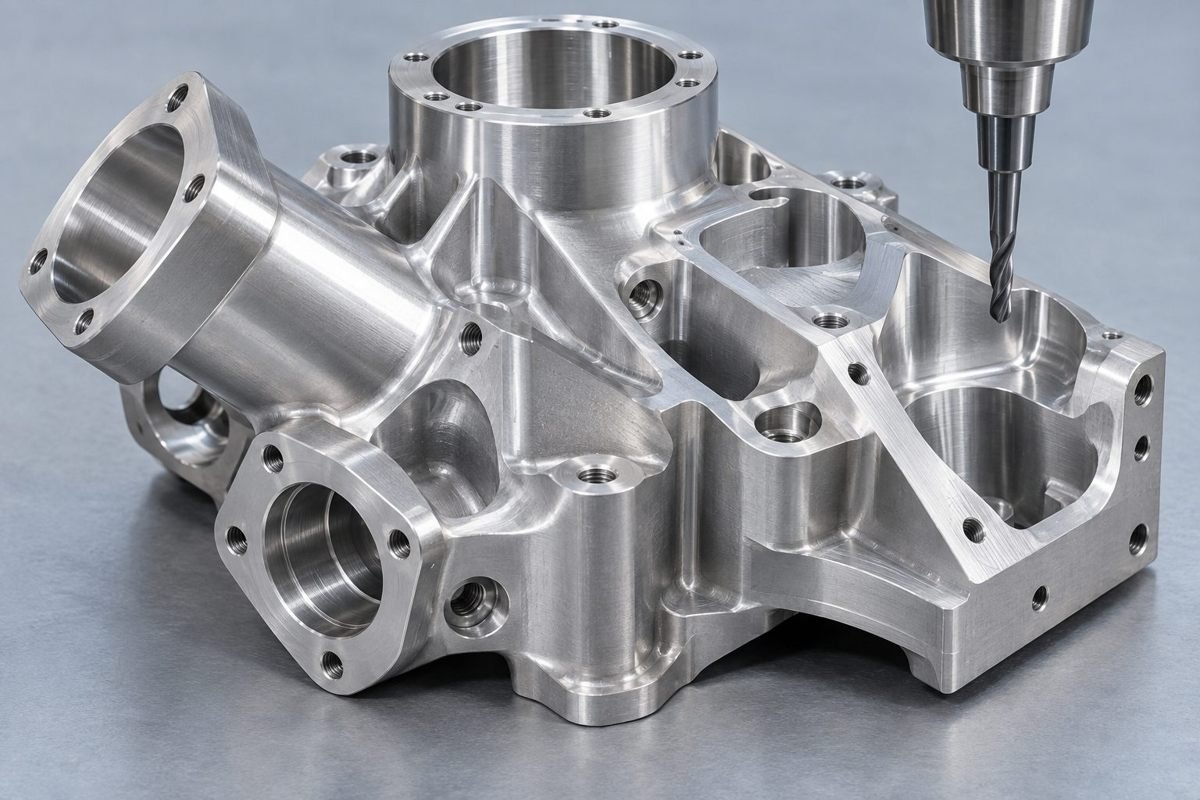
Consider the complete tool and holder, not just the cutting edge. Hard-to-reach features can require extra setups or a different machining approach.
Reduce avoidable setups and clarify the route before production.
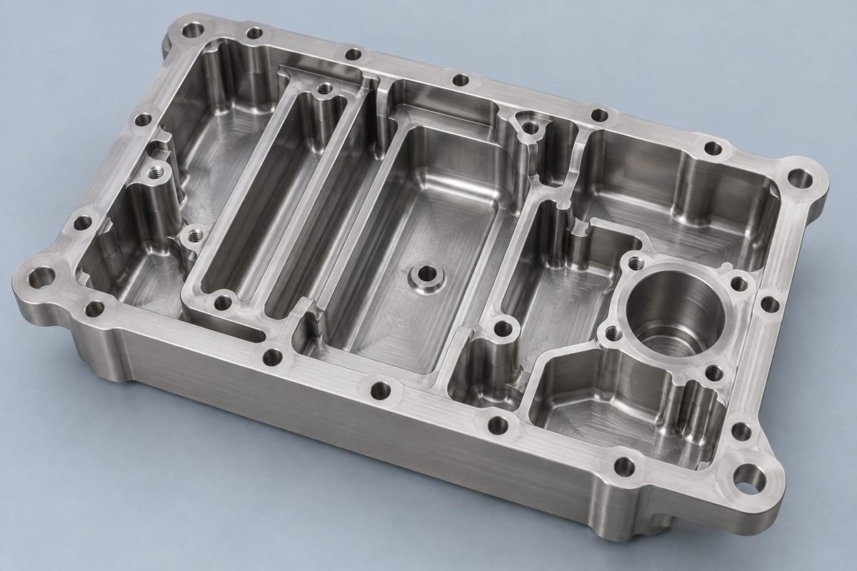
Deep, narrow cavities can force long tools that deflect or vibrate. Review depth, width and corner radii together.
Control machining time while protecting your pocket geometry.
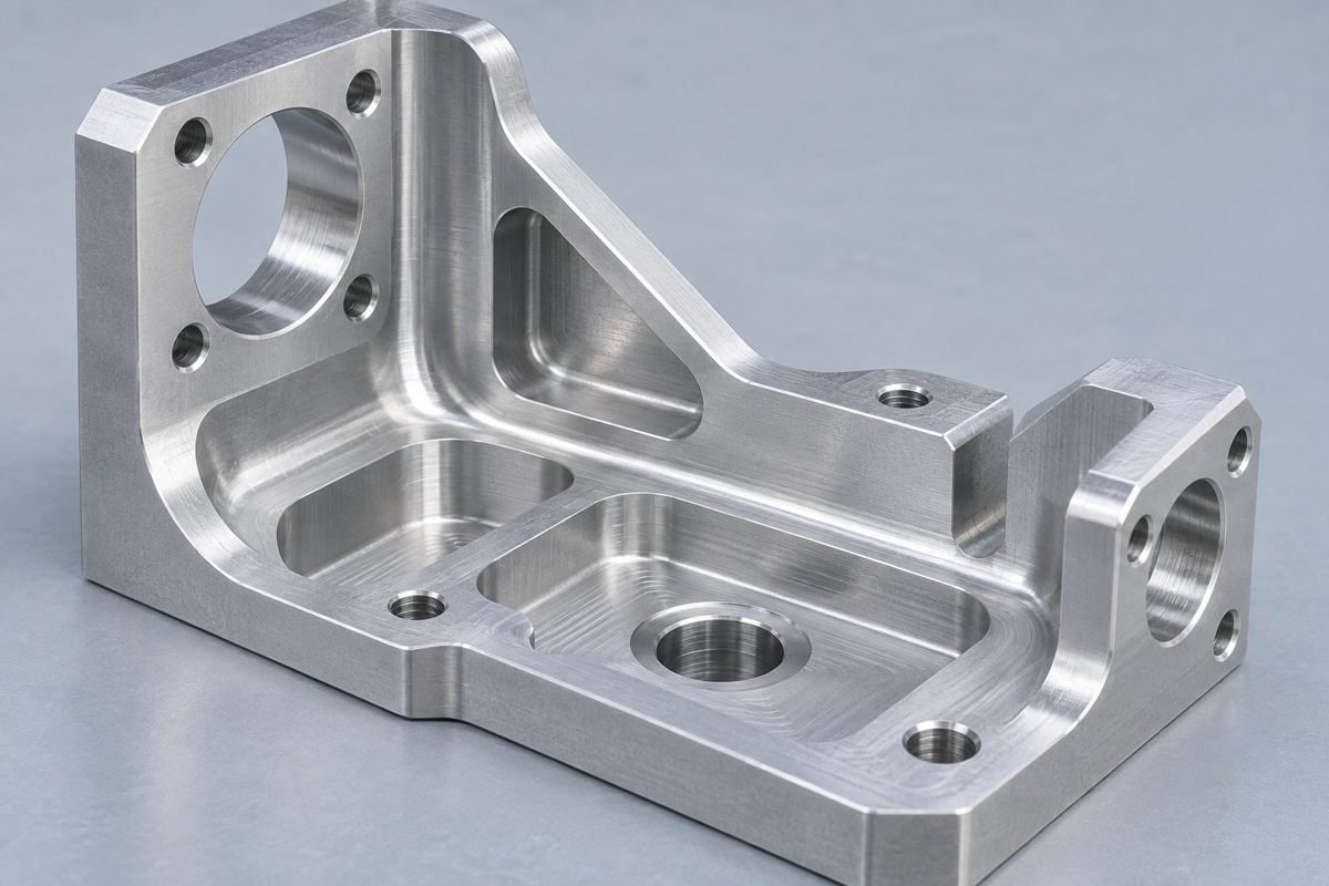
A rotating end mill leaves a radius in an internal vertical corner. Review mating-part clearance instead of assuming a sharp corner is possible.
Keep your mating features functional with a practical cutting route.
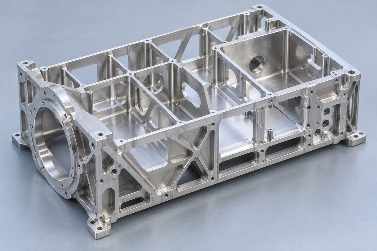
Slender walls and ribs respond to clamping and cutting loads. Their material, height and support matter as much as nominal wall thickness.
Reduce distortion and make your inspection requirements clearer.
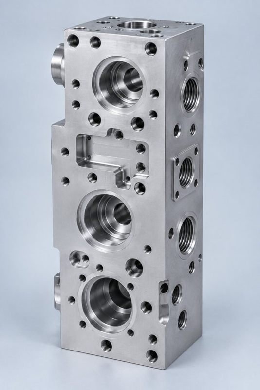
Separate total hole depth from useful thread depth. Deep drilling, intersections and blind-hole bottoms need a reviewed tool and chip-removal plan.
Avoid ambiguous holes, incomplete threads and hidden burr risks.
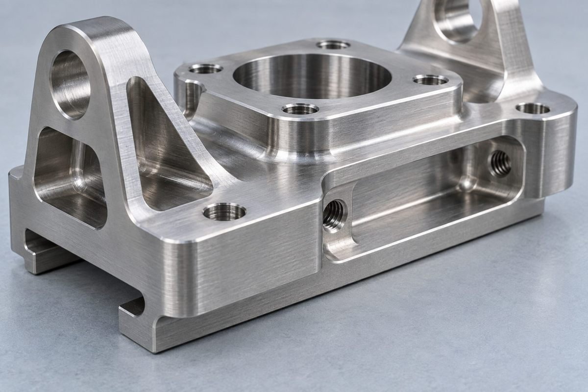
More machine axes do not make every recess accessible. Tool shape, entry path and nearby geometry determine whether an undercut can be machined.
Understand your added tooling and setup needs early.
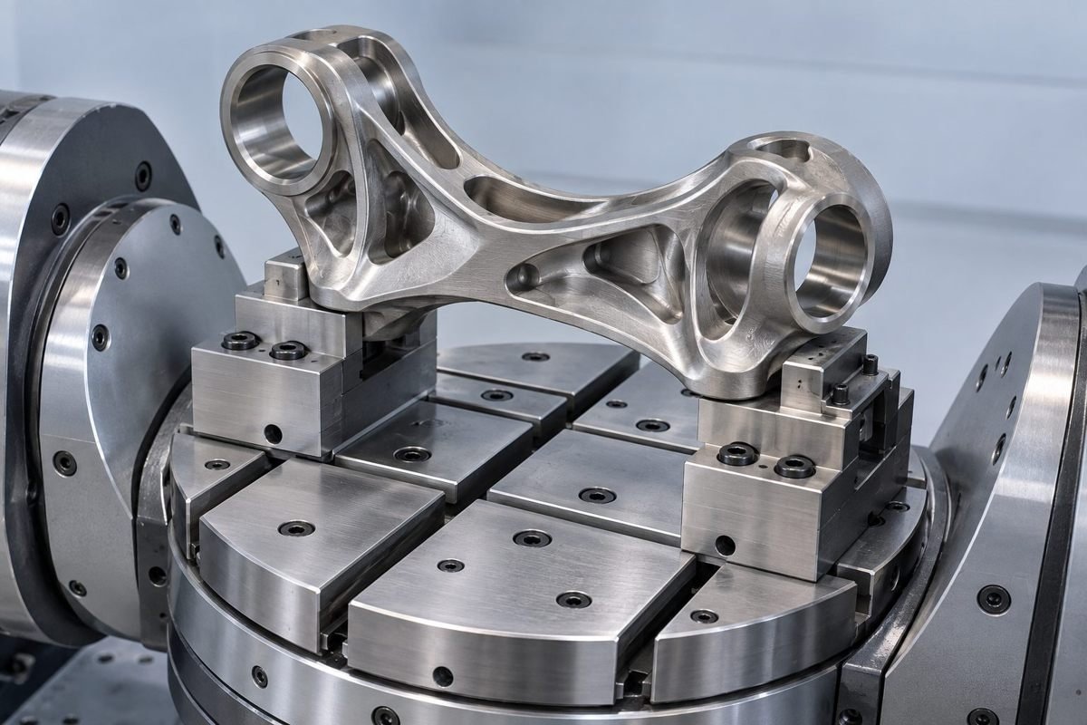
Plan how your part will be located and supported before finishing its most important faces and bores.
Preserve the feature relationships that control your assembly fit.
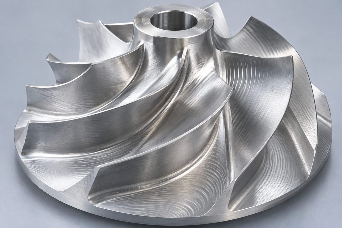
A finish requirement can change cutting time and post-processing. Identify the surfaces that need controlled texture or appearance.
Align your delivered condition with your drawing and end use.
Need a broader review? Explore design for manufacturing support →
MAKE YOUR BUDGET WORK HARDER
Start with function: identify what your part must do, then review the specifications that add cost.
More repositioning can add fixture work and datum transfers.
Grade and condition influence tooling, speed and availability.
Stock volume and machining envelope affect your route.
Deep pockets and hard-to-reach features add cutting time.
Critical dimensions may need extra control and measurement.
Finishing, masking and handling add process steps.
Report scope and sampling affect your project effort.
COMPARE YOUR OPTIONS
The best process depends on your complete drawing. More axes alone do not guarantee a lower price or tighter tolerance.
| Your decision | 3-Axis Milling | 4-Axis Milling | 5-Axis Milling |
|---|---|---|---|
| Best fit | Pockets, faces and accessible bores | Features distributed around a rotary axis | Angled features and compound surfaces |
| Setup review | Additional faces may need re-clamping | Indexing may combine several operations | Multi-axis access may reduce repositioning |
| Tool access | Fixed cutting directions | Rotary indexing or coordinated motion | Indexed or simultaneous tool orientation |
| Surface requirements | Review tool marks and reach | Review indexing and finish continuity | Review contour strategy and tool orientation |
| Cost decision | Compare geometry and setup time | Compare fixtures and programming | Compare complexity, verification and cycle time |
MATERIALS & FINISHES
Review grade, condition, finish compatibility and material records in your quote.
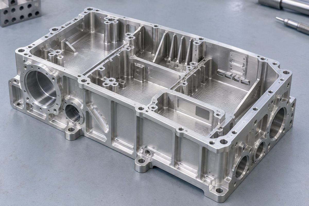
Lightweight housings and structural parts. Confirm your grade and temper.
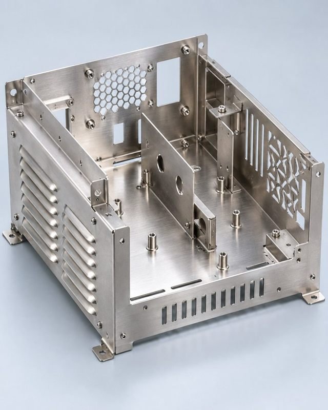
Corrosion resistance and strength. Specify grade and surface condition.
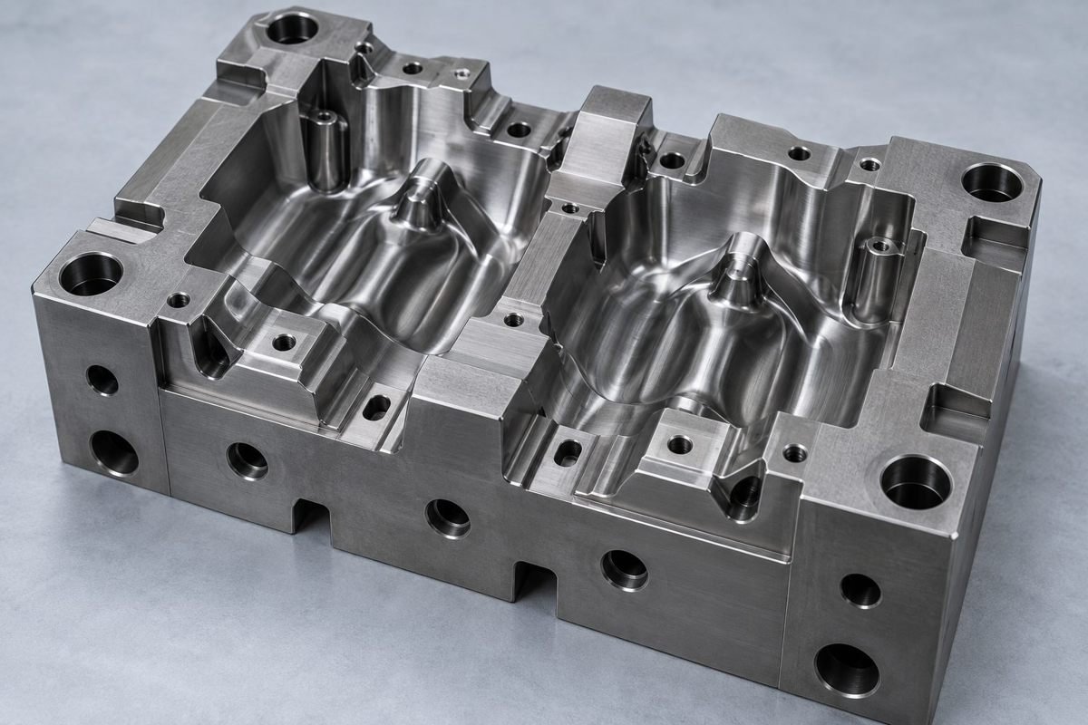
Tooling and wear applications. Review hardness and heat treatment.
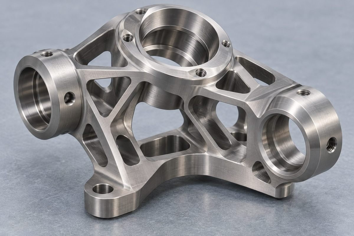
High strength-to-weight needs. Review grade, geometry and cutting time.
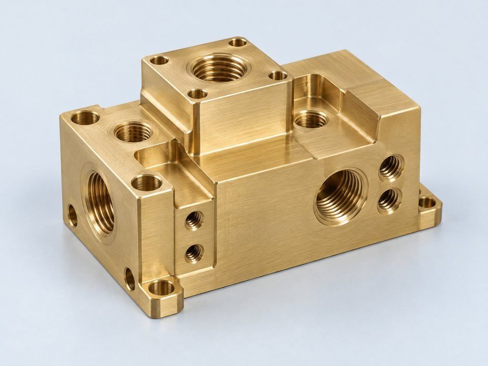
Fluid and conductive interfaces. Confirm the alloy for your use.
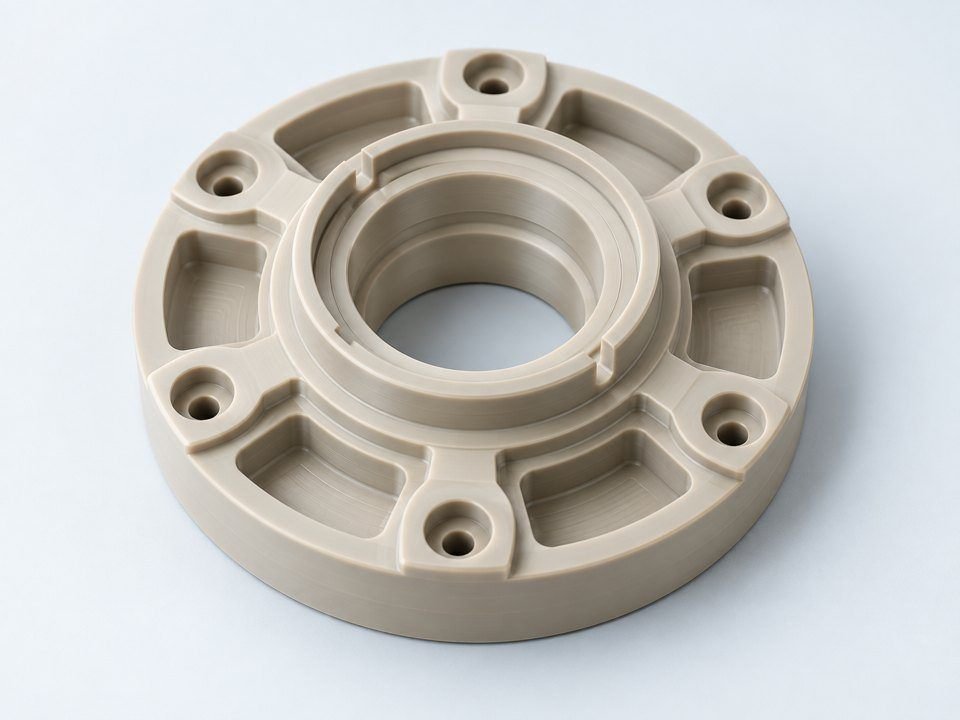
Functional polymer parts. Review stability, load and temperature.
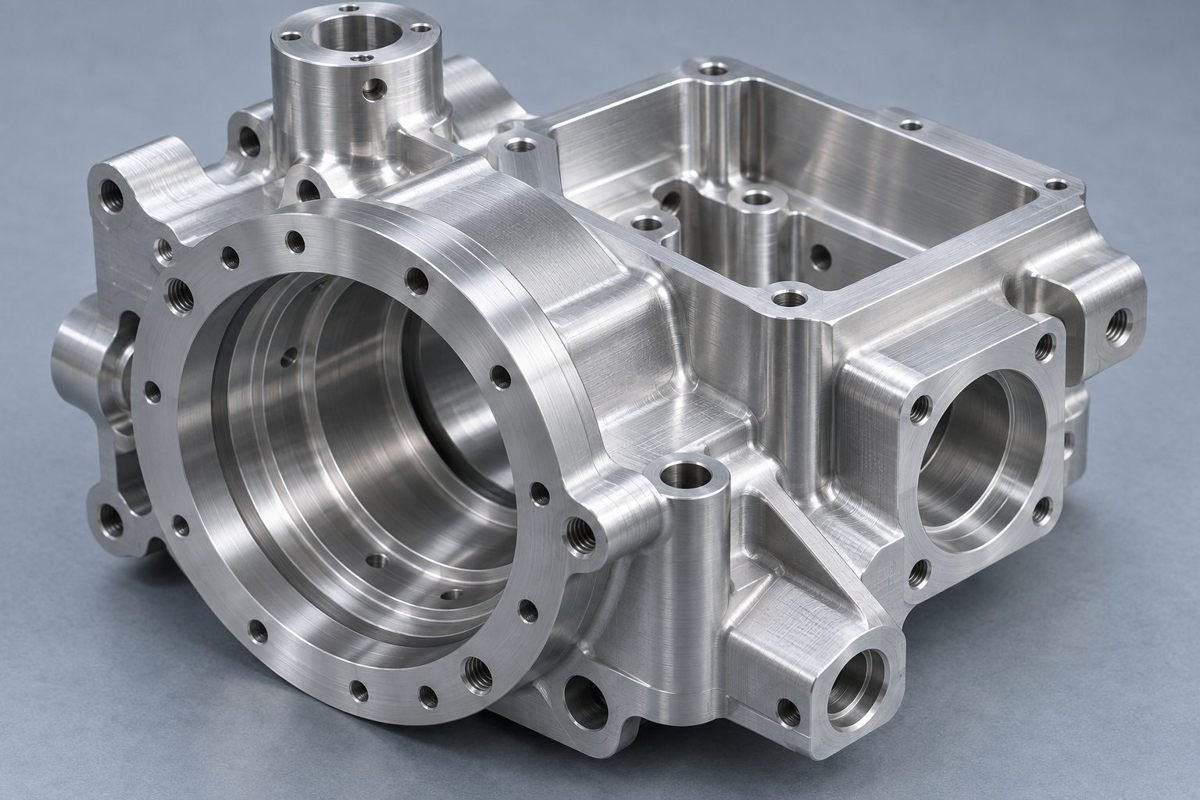
Define tool marks and edge requirements.
Review texture and masked interfaces.
For suitable aluminum alloys; allow for coating.
For suitable stainless steel parts.
Review coating thickness and substrate.
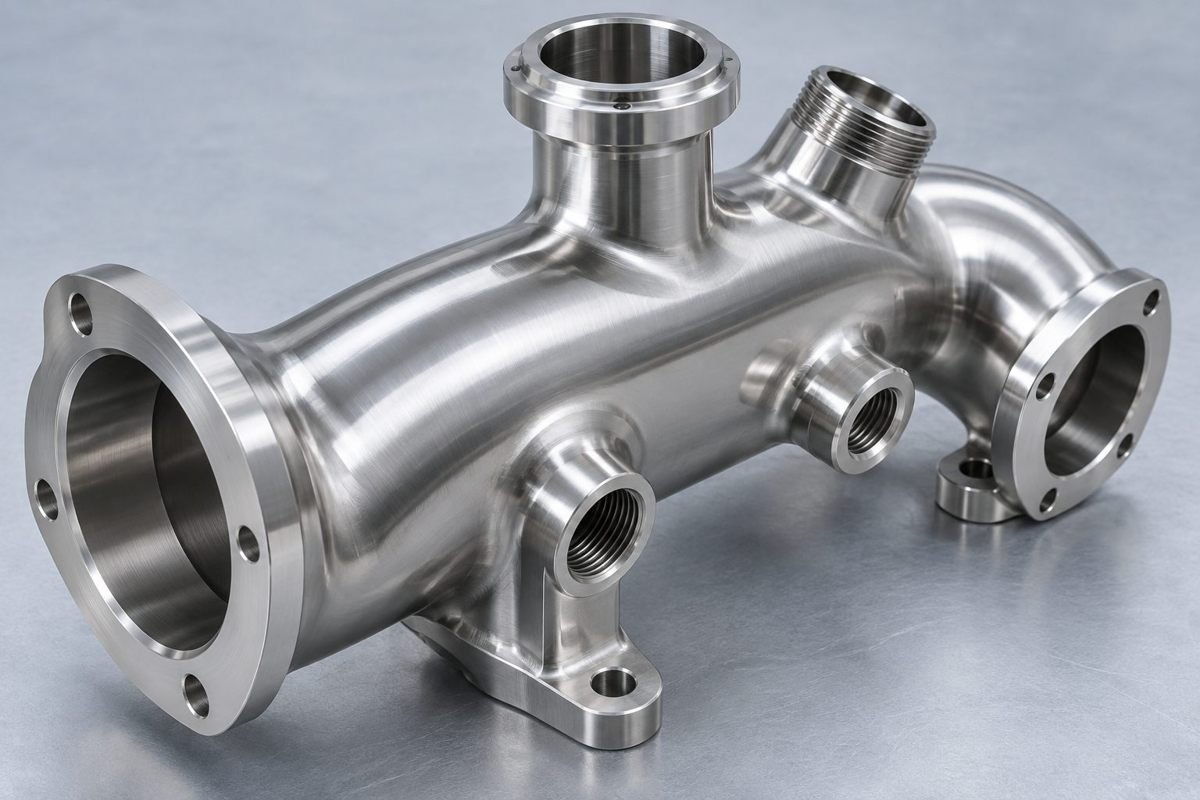
Define appearance and dimensional limits.
FROM PROTOTYPE CNC MILLING TO REPEAT PRODUCTION
Keep your design, inspection and approval requirements connected from the first sample onward.
Your geometry, grade, quantity and critical features.
Agreed design changes, datums and workholding.
Parts for your fit and functional validation.
Your agreed measurements and report scope.
Your approved revision and delivered condition.
Your release quantities, packaging and destination.
YOUR MANUFACTURING SEQUENCE
Coordinate each operation around your drawing, material and acceptance requirements.
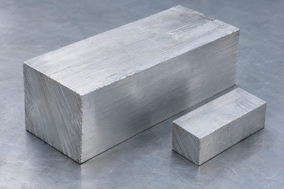
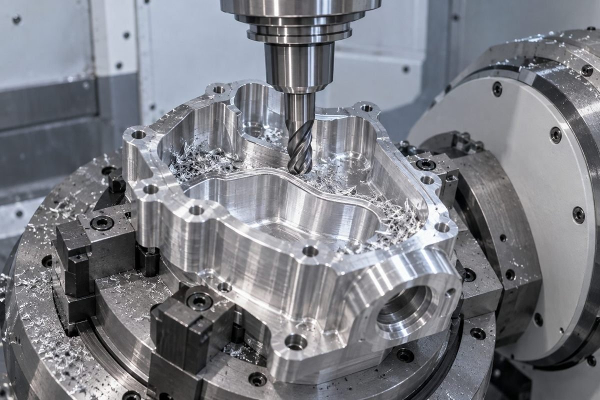
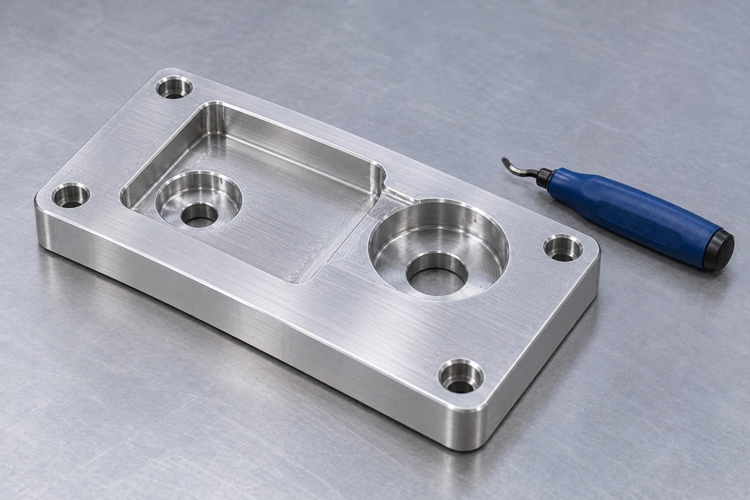
PRECISION YOU CAN VERIFY
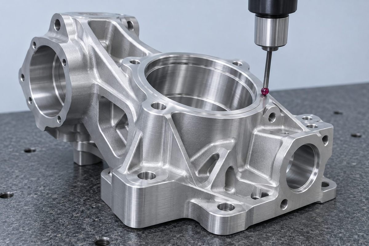
Specify what matters to your assembly. Achievable tolerances are reviewed for your geometry, size, material and finish.
Your critical dimensions and agreed sampling.
Measurement method matched to your features.
Sample approval evidence agreed in advance.
Submission scope confirmed for your program.
Specified grade and requested certificates.
Your functional datums and feature relationships.
Your finish, masking and edge requirements.
Agreed revision and production records.
INDUSTRIES & APPLICATIONS
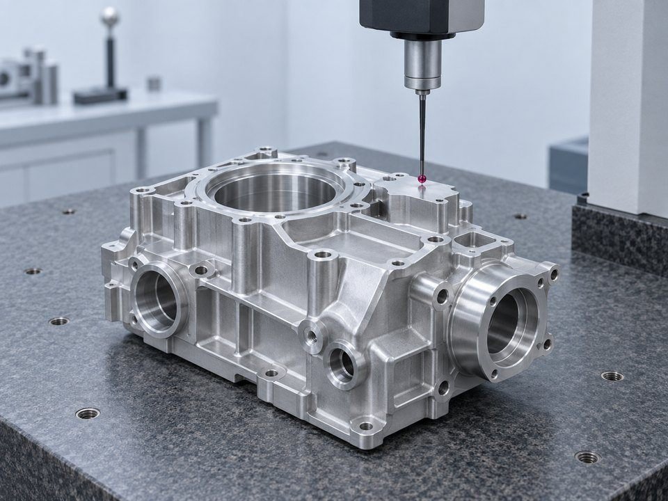
Review your specific geometry, material and documentation needs with your application in mind.
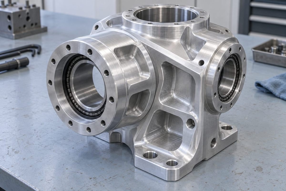
Housings and joint interfaces.
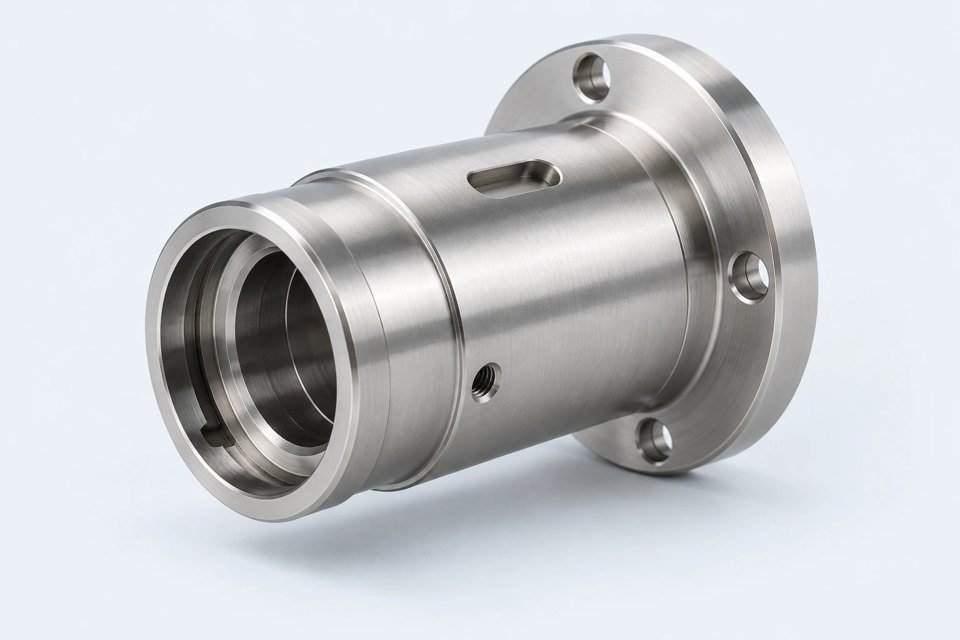
Instrument mounting components.
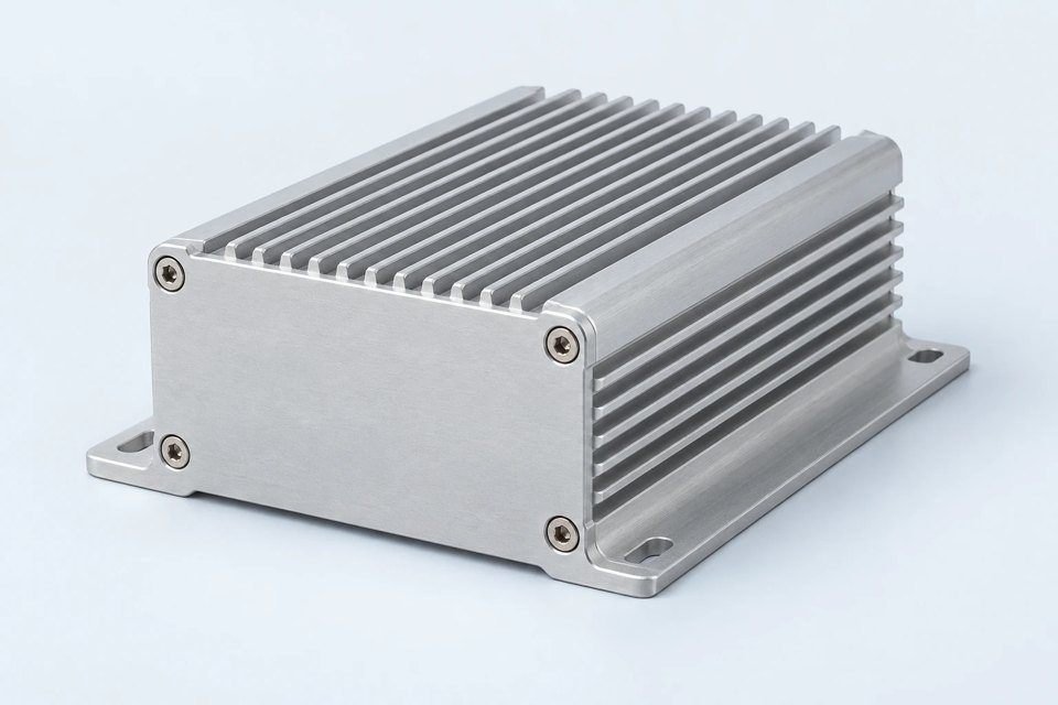
Precision enclosures and fixtures.
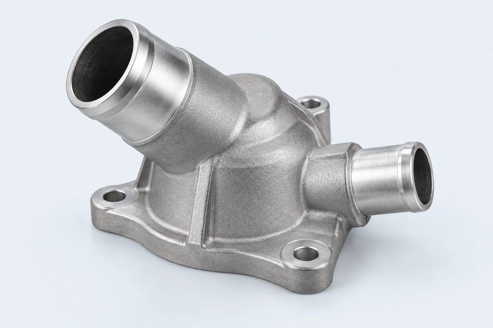
Power and thermal interfaces.
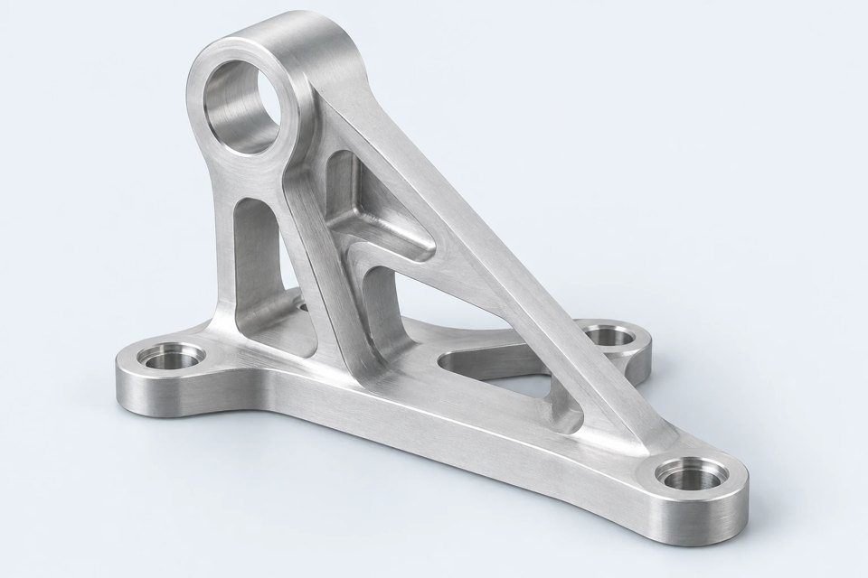
Lightweight structural geometry.
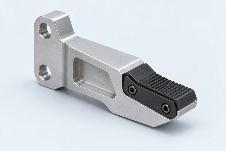
Jigs and production fixtures.
YOUR QUESTIONS, ANSWERED
Send your 3D STEP or STP file, a controlled 2D drawing, material grade, quantity and delivery target. Mark critical tolerances, threads, finishes and inspection requirements so the quote reflects your acceptance criteria.
Start with your geometry and tool access. Accessible prismatic features may suit 3-axis milling; features around several sides may benefit from indexing; angled or contoured features may need 5-axis access. Compare the full setup, programming and inspection plan.
Your drawing is reviewed against part size, geometry, material, workholding and finishing. Identify critical dimensions and datums. The accepted tolerances and measurement scope are confirmed for your project before production.
Yes. Request a DFM review of tool access, pocket depth, internal radii, thin walls, holes, undercuts and workholding. Design changes should preserve your functional requirements and be agreed before release.
Share your initial quantity and expected repeat demand. Review prototype validation, first article acceptance and revision control so your approved requirements carry into later orders.
Choose around your load, corrosion, thermal, appearance and assembly requirements. Include the exact grade and condition. Review coating allowance, masking and dimensional effects on mating features.
Material availability, geometry, setup count, tolerances, finishing and inspection all affect the schedule. Send your required date with the drawing so availability and the complete route can be reviewed.
Include your report, material record, traceability or first article requirements with the quote. The measurement method, sampling and documentation scope are agreed for your order.
GEOMETRY EXAMPLES
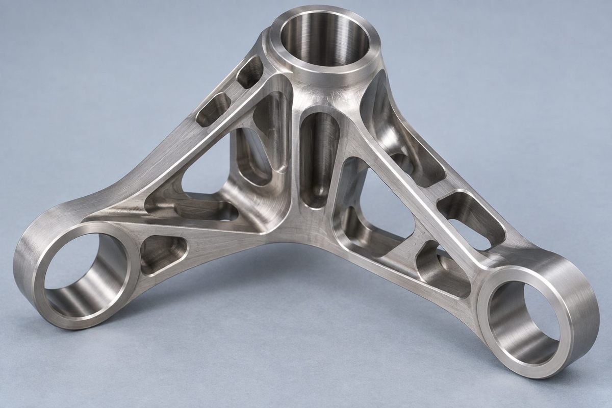
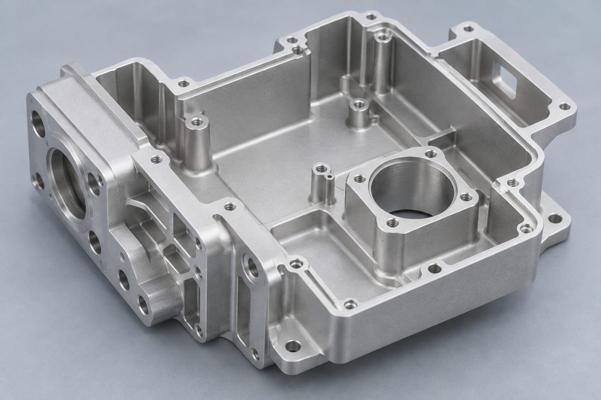
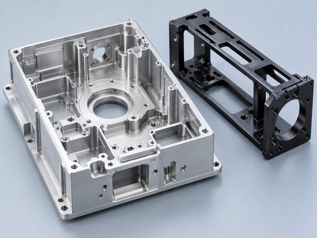
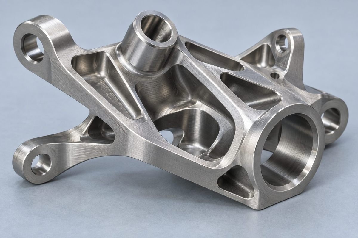
Review your bore alignment and mounting datums.
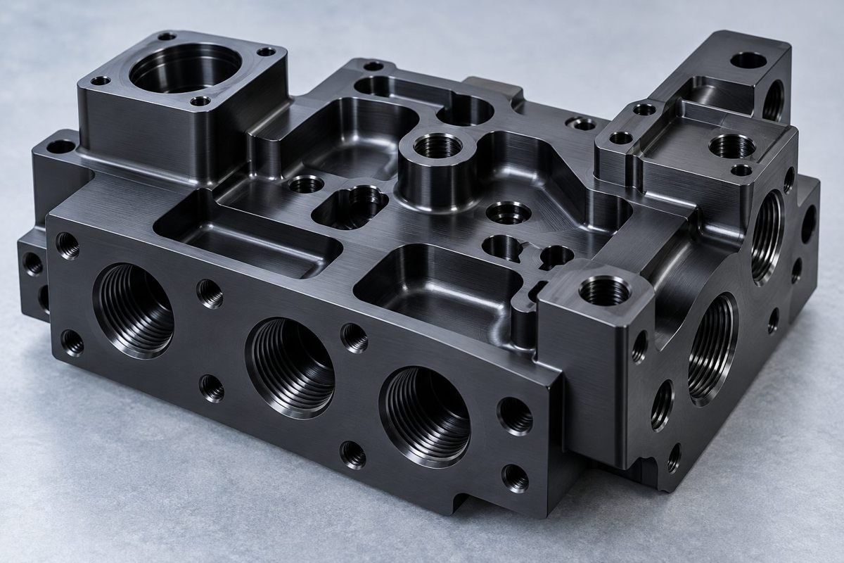
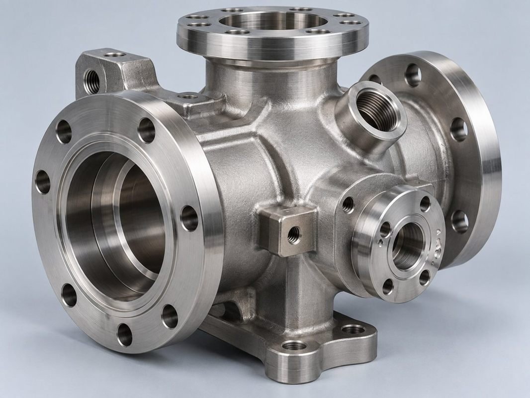
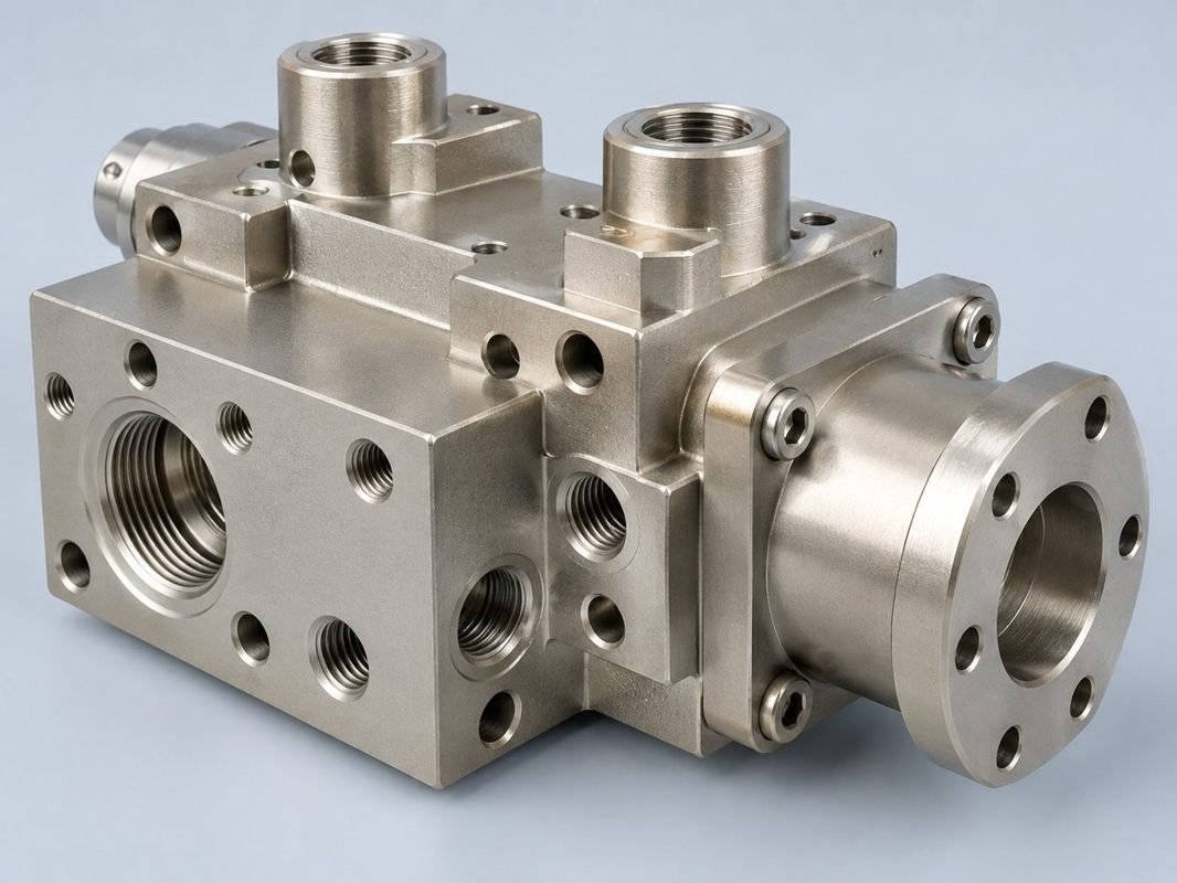
Review your ports, sealing faces and intersecting holes.
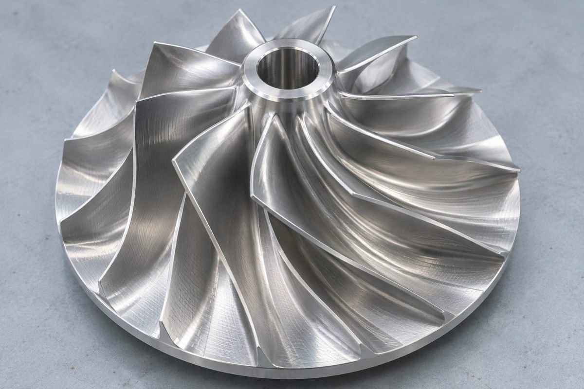
Review your blade surfaces and bore relationship.
Illustrative component and process concepts; not customer case studies.